Note: Descriptions are shown in the official language in which they were submitted.
CA 02194858 2005-02-10
1
SHORT STRAND ORIENTER
Field of Invention
The present invention relates to a strand orienter, more particularly, the
present
invention relates to a multi-deck strand orienter for orienting strands
without significant
segregation of the strands by length.
Background of the Invention
The concept of orienting stands by passing the stands through narrow vertical
passages (compared with the axial length of the strands to be oriented) is
practised in the
wafer board or strand board industry and has been for some time.
One such device is shown in U.S. patent 3,115,431 issued December 24, 1963, to
Stokes et al. This device includes the plurality of intermeshed rotating disks
mounted on
a plurality of substantially parallel side-by-side shafts positioned in a
plane. The disks on
the shafts are uniformly positioned intermediate disks on their adjacent
shafts. In the
arrangement described, the disks on adjacent shafts turn in the same
direction, except for
the last disks in the sequence which turn in the opposite direction. This type
of
arrangement (hereinbelow referred to as the Stokes arrangement or the Stokes
disk
arrangement) has been found satisfactory particularly for use with long
strands.
Another similar device is shown in the Burkner U.S. patent 4,666,029 issued
May 19, 1987 but wherein the disks on adjacent shafts are arranged in pairs in
side by
side relationship with the disks forming one of the pairs defining one side of
an orienting
passage and the disks forming the next axially space pair defining the other
side of the
passage. This arrangement (hereinafter referred to as Burkner arrangement) is
also
satisfactory but the Stokes arrangement is less complicated and appears to be
about as
effective in aligning the strands as the Burkner arrangement.
Both of these devices use their rotating disks to carry the longer length
strands
that did not pass directly between the axially spaced disks along the top of
the disks
toward
219858
2
one end where the axial spacing between the disks is wider so that the long
strands are
preferentially positioned towards one end of the orienter and the short
strands at the other.
In a modified version of the arrangements as described in Crittenden et al.'s
U.S.
patent no. 5,325,954 issued July 5, 1994, at least a pair of decks, i.e.
preorienter and
orienter are used. This significantly improved the operation of the system and
better
ensures that the strands, in particular, long strands over about 6 inches pass
through the
vertical passages in the bottom orienting deck more easily by first tipping
the strands via
the disks in the preorienter and directing them more effectively into the
relatively narrow
passages in the orienter. This system provides a significant improvement over
both the
Burkner and Stokes arrangements and is particularly suited for handling long
strands.
The orienting system of US patent 5,325,954 generally employs a relatively
long
bottom deck with wider axial disk spacing toward one end of the orienter, but
does not
segregate the strands by length to the extent that occurs with the Burkner and
Stokes
arrangements.
It is known that the height of the lower edge of the bottom orienting deck
above
the mat or lay-up formed on the collecting belt has a significant influence on
the retained
orientation of the wafers or strands on the belt. The larger this space the
greater the loss
of orientation of the strands as attained in the orienter, thus it is
preferred to keep this
distance relatively small in the order of between 1 and 3 inches, preferably
smaller to
2 0 minimize this loss of orientation.
It will be apparent, if there is segregation of the strands by length, the
strands are
laid on the collecting belt over a longer length of the belt. This is not in
itself a problem,
however, if the distribution of strands along the length of the orienter is
not uniform, the
height of the mat above the belt will build at a nonuniform rate so that the
height of the
2 5 mat above the belt will form a hump towards one end of the orienter.
This means that the sloped bottom deck of the orienter must be adjusted to
accommodate the hump so that the spacing between the bottom deck and the top
of the
strands on the belt may be set at the desired distance at the top of the hump
but anywhere
off the hump, so that the average angle of orientation of strands in this part
of the orienter
3 0 is significantly increased, i.e. orientation is lost.
CA 02194858 2005-02-10
3
U.S. patent 3,807,931 issued April 30, 1974 to Wood et al. describes another
form of orienter which uses a number of vertically stacked decks each formed
by
stationary vertical fins each provided with a vibrating cap that improve
movement of the
wood particle there between. Each deck has a number of fins that is a multiple
of the
number of fins in the deck immediately above it so that the fins on the upper
deck
directly overlie corresponding fins on the lower deck and the flow of strands
is divided
by the upper deck and the divisions so formed further subdivide by the next
lower deck.
In this device, the spacing between the fins on the top deck is about half the
average
length the strands that are to be oriented and the spacing between the upper
and lower
deck is defined as the distance greater than the average length of the
strands. The
orienting system of this patent clearly would not be effective for long wafers
nor would it
function well for conventional length (3 to 4 inch) strands.
Canadian patent 920,529 issued February 6, 1973 to Turner et al. shows yet
another form of orienter wherein partition walls are designed to move to
prevent
plugging.
Brief Description of the Present Invention
The present invention provides a multi-deck orienting system controlling the
strand throughout their passage there through to minimize segregation of the
strands by
length and reduce the possibilities of strands being caught in the orienter
and causing
blockage.
Accordingly, the present invention provides an orienting system for orienting
wood strands comprising at least three decks including a top deck, a bottom
deck and at
least one intermediate deck between said top and bottom decks to form a series
of said at
least three decks stacked substantially vertically one directly above the
other,
substantially vertically extending passages through each of said decks, each
of said
passages in each of said decks having a width defined by a pair of spaced
walls, said
decks being in vertically adjacent pairs, each of said pairs composed of an
upper deck
which may be one of said top deck and said at least one intermediate deck and
a lower
deck which may be one of said bottom deck and said at least one intermediate
deck, said
passages through said bottom deck having a preselected width y measured in a
first
direction between and substantially perpendicular to said walls of said bottom
deck, said
CA 02194858 2005-02-10
4
width y being sufficiently small to ensure orientation of said strands passing
therethrough to the desired mean angular deviation relative to a second
direction
substantially perpendicular to said first direction, said passages in an upper
deck of each
pair of vertically adjacent decks in said series have widths measured in said
first
direction correlated with passage widths of passages through its adjacent said
lower deck
of said pair of decks so that a passage through said upper deck of each said
pair of
adjacent decks is divided into two passages by passages directly therebelow
formed
through its adjacent said lower deck of said pair of vertically adjacent
decks, the
combined widths of said two passages directly therebelow being equal to the
width of
said passage through said upper deck so that strands falling downward though a
passage
in said upper deck may fall directly onto only one top edge of a common wall
between
its said two passages directly therebelow in said lower deck, said top deck
forming an
upper deck of one of said pairs of vertically adjacent decks and said bottom
deck forming
a lower deck of another of said pairs of vertically adjacent decks and each
said
intermediate deck forming an upper deck with its vertically adjacent lower
deck and a
lower deck with its immediately adjacent upper deck and wherein said walls of
said
passages in each said upper deck in each said pair of vertically adjacent
decks are
substantially vertically and axially aligned one with each outer walls of a
pair of adjacent
of said passages directly therebelow in its said lower deck immediately
therebelow.
Preferably, said vertical passages in each of said intermediate and said top
decks
positioned above said bottom deck have a width substantially equivalent to
(2)" y for a
Stokes disk arrangement where n is the number of decks above said bottom deck.
Brief Description of the Drawings
Further features, objects and advantages will be evident from the following
detailed description of the preferred embodiments of the present invention
taken in
conjunction with the accompanying drawings in which;
Figure 1 shows a schematic arrangement of a plurality of orienting systems
constructed in accordance with the present invention and arranged in side by
side
relationship.
2194858
Figure 2 is a section parallel to the direction of belt movement through a
typical
orienting system constructed in accordance with the present invention.
Figure 3 is a schematic section along the lines 3-3 of Figure 2 illustrating
the
preferred arrangement of the disks forming the side walls of the passage.
5 Description of the Preferred Embodiments
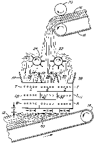
Figure 1 shows an orienter incorporating three orienting systems constructed
in
accordance with the present invention as indicated at 1, 2 and 3 arranged in
side by side
relationship for laying a mat or lay-up indicated at 12 on a conveyor or the
like 14. The
mat 12 forms a lay up for manufacture of consolidated composite wood products
from the
material (wood strands) orienters l, 2 and 3. It will be apparent that while 3
orienting
system constructed according to the present invention have been shown in
figure 1 show
how the systems may be -placed to take full advantage of a specific type of
distribution
system feeding an orienting system constructed in accordance with the present
invention
i.e. any one or more of the systems 1, 2 or 3 may be used independently or in
combination
with other orienting systems of the present invention.
The wood strands normally used with the orienter system of the present
invention
may have any reasonable length - generally, less than about 12 inches, a
thickness less
than about .25 inches, normally less than about 0.05 inches, a width generally
about 1/2
inch and up to about 3 inches with a length to width aspect ratio of at least
2.
2 0 In the arrangement illustrated, strands 16 are fed from a conveyor or the
like 18
using a spiked picker roll or the like 20 to disperse the strands and feed
them onto a pair
of spaced apart distributing rolls 22 and 24 which are also in the form of
spiked rollers
mounted in parallel spaced part relationship so that in the illustrated
arrangement, about
one third of the strands pass between distributor rolls 20 and 24 and form an
in-feed for
2 5 the orienting system 2, i.e. the middle orienting system, whereas the
distributing roll 22
distributes another third of the flow onto the orienting system 3 and the roll
24 distributes
the final third onto the orienting system 1. Preferably, but it is not
necessary, the flow to
'each of the orienting systems 1, 2 and 3 will be essentially the same.
The incoming flows for the orienting systems 1, 2 and 3 as indicated at 26, 28
and
3 0 30 fall between partitions or directing walls 32, 34, 35, 36, 37, and 38
which delineate at
2~948~8
6
least the incoming width of the strands 26, 28 and 30 and may, as will be
described
below, carry on to form boundary walls between the orienting systems 1, 2 and
3. These
directing walls 32, 34, 35, 36, 37 and 38 direct the strands onto the upper or
top deck of
these respective orienting systems 1, 2 or 3 toward the periphery of the
outside disks at a
length preferably just inside of a vertical plane passing through the axis of
those outside
disks (see the partitions 32 and 34 in Figure 2).
With the orienting systems of the present invention, substantially all of the
strands
in the flows 26, 28 and 30 passed directly through their respective orienting
systems 1, 2
and 3 and leave their respective orienting systems over a relatively short
length as
indicated at x in the direction of movement of the conveyor.
This arrangement where the incoming strands in the flows 26, 28, 30 each pass
out through its respective orienting systems 1, 2 and 3 as a relatively narrow
stream
measured in the mat or lay up length direction (x) ensures that there is
substantially no
segregation of the strands by length rather the strands are laid in a more
homogenous
manner. Generally, the length x will be in the range of about 1 to 3 feet.
Furthermore, by concentrating the laying of the strands over a relatively
short
length x, the spacing z between the bottom of the orienting system and the top
40 of the
mat being formed may be maintained relatively constant as indicated by the
dimension z
in Figures 1 and 2.
2 0 In the illustrated arrangement, the side by side orienting systems 1, 2
and 3 have
been aligned horizontally. However, assuming the orienting system 1 is the
datum, the
orienting system 2 may be moved vertically as indicated by the arrow 42
relative to the
system 1 and similarly the orienting system 3 may be displaced vertically as
indicated by
the arrow 44 relative to the orienting system 2 to position the bottom of each
of the
2 5 orienting systems relative to the top 40 of the mat being formed as
required, i.e. if the
spacing between the disk decks is significant, it may be more desirable to
arrange the
decks in a stepped relationship with the deck 3, i.e. upstream in the
direction of movement
in the belt being positioned closer to the belt than the other two.
It will be apparent that though three orienting systems 1, 2 and 3 have been
shown
3 0 in combination, present invention may be employed with a single orienting
system or
2194858
with two or more orienting systems. The use of three orienting systems is
relatively
convenient when a pair of distributing rolls, 22 and 24, are used as the main
flow may be
relatively easily be divided into three separate flows from a single source.
As schematically illustrated in Figure 2, each of the orienting systems (only
one
will be described) is formed by at least three decks, a bottom deck B, at
least one
intermediate deck I~;~ and a top deck T (see also Figure 1).
In the illustrated arrangement, only one intermediate deck has been shown.
However, as indicated by the ~;~ a number of intermediate decks may be
provided as
required to satisfy the requirements for the number of passage bisections
based on the
width y required in the bottom deck to obtain the required orientation and the
length L of
the strands being oriented as will be described below.
It is important that the disks 44 be driven and suitable means schematically
represented by the arrows 52 will be provided to drive the disks 44 - normally
by driving
the shafts 46. In the illustrated arrangement the disks at one end (off going
end) of the
orienting system in each deck have been shown driven in the opposite direction
to the
other disks, however, this is not essential or even preferred.
The axes of the shafts 46 in the different decks are preferably arranged in a
grid
pattern. The axes of the shafts in a given deck are preferably all positioned
in a plane (see
planes 54, 56 and 58 designated by dot dash lines in Figure 2) and the axes of
the shafts in
2 0 the series of stacked decks being positioned in stacked relationship in
planes 60, 62, 64,
66 and 68 which are preferably substantially parallel. The planes 54, 56 and
58 are
preferably parallel and extend in a direction preferably substantially
perpendicular to the
direction in which planes 60, 62, 64, 66 and 68 extend. Though the planes 54,
56 and 58
have been shown to extend substantially horizontally they may if desired be
set to be
2 5 substantially parallel to the top 40 of the mat being formed.
In any event, in the arrangement illustrated in Figure 2, each of the decks B,
I~;~
and T are formed by a plurality of disks 44 mounted in axially spaced
relationship on
shafts 46. In the illustration in Figure 2, the shafts with the top deck T
have been
indicated by a t. Also, the position of shaft relative to one end (front) has
been indicated
3 0 numerically, i.e. in the 5 shaft system illustrated, as , for the shaft
closest to the front 48
219858
8
and 5 to the shaft farther from the front 48. Similar numbering has been used
in each of
the decks. Each of the intermediate deck being designated as h;~ the ~;~
indicating the
position or number of decks that intermediate deck is above the bottom deck B
and the
shafts are indicated in a similar manner, i.e. 46~,I,~ is the front (first)
shaft on the
intermediate deck immediately above the bottom deck B. The disks and shafts on
the
bottom deck B being indicated by the similar reference numerals but with the
subscript B
indicating the bottom deck, e.g. 46,B.
In the illustration, all the disks, 44T, 44L and 44B have essentially the same
diameter D.
The spacing between the adjacent disks mounted on substantially vertically
aligned shafts, i.e. shafts 46~,.~, 46~,I,>, 46~~, etc. is indicated by the
dimension t. 'This
dimension t will normally be less than 2 inches and is likely to be closer to
1 inch and
may be a negative number where the disks overlap.
Overlapping of the disks in one deck with disks in the adjacent higher or
lower
deck may be important where the overall height or the orienting system is
important as
overlapping significantly reduces the height of the system. The degree of
overlap
obviously must not be sufficient and the disks must be positioned on adjacent
decks to
ensure there is no interference between for the disks ion adjacent decks and
one deck does
not interfere with the operation of its adjacent decks.
2 0 The dimension D is correlated with the diameter d of the shaft 46 and the
spacing
S between shafts 46 in the same deck to ensure that the clearance between the
shafts 46 in
each deck is at least equal to the length of strand to be processed, i.e.
1/2(S-d) will
normally be equal to at least the maximum length L of a strand being processed
(see the
strand 52 at the top of Figure 2) and D/2 = r will be slightly less than S-d
to provide
2 5 clearance..
Applicant has found that the dimension D of 16 inches using shafts of diameter
equal to about 2 inches and spaced 9 inches to operate very satisfactory with
wafers or
strands having a maximum length of less than about .61/2 inches and an average
of about
51/2 inches.
'' 2194858
9
In the illustrated arrangement, the disk have been shown arranged as described
as
above as a Stokes arrangement. However, they can equally well be arranged as a
Burkner
arrangement. The Stokes arrangement is however, preferred since the number of
decks
required may be reduced relative to a Burkner arrangement.
It is important that in any pair of adjacent decks in the sequence e.g. decks
h,~ and
B that the strands falling through the passages P~,~ in deck h,~ to the
passages P~~ can
contact only one edge i.e. only the top of one of the walls of the passages
P~~ in the deck
B so that each passages P~,~ in an upper deck of the pair of adjacent decks is
bisected into
two passages P~~ through the lower deck of the pair. Preferably the passages
in the upper
deck will be bisected into two equal width passages in the lower deck and the
total width
of the two passages in the lower deck will be equal to the width of the
passage in the
upper deck of the pair (ignoring the disk or wall thickness measures axially
of the shafts.
As shown in Figure 3, the axial spacing between the adjacent disk 44 measured
between the center of the disks (axial of the shafts - ignoring the disk or
partition wall
thickness measured axially of the shafts) in each of the deck is set up as
follows: The
axial spacing of the disk 44 on the deck B is set at the dimension Yb which is
the required
dimension to obtain the desired degree of orientation (mean angular deviation)
of the
strands forming the mat 12, then each of the decks positioned thereabove will
preferably
be sized in relation thereto to ensure that the vertical passages defined
between the disks
2 0 in each deck, i.e. the passages PT, Pu;~ and PB will increase in width
according to the
following formula:
Y~,;~ - 2~°~YB
wherein YB equals the width of the passages in the bottom deck, i.e. with the
passages PB
and n equals the position of the deck above the bottom deck counted from the
bottom, i.e.
2 5 the bottom deck is not counted (i.e. the bottom deck B is equal to n=0),
the first
intermediate deck is the first deck (n=1), etc. In the illustrated
arrangement, the deck h;~
will be first deck up and the dimension Y~;~ will be twice the dimension YB
and the
dimension YT of the upper deck, since there are only three decks, will be
equal to 2~2~ YB
or 4 times YB .
CA 02194858 2005-02-10
It will be apparent that with the Stokes disk arrangement, the number of decks
required is reduced relative to a Burkner arrangement since the width YT is
defined by
disks on adjacent shafts bisecting the space between decks on the same shaft,
i.e. in the
Stokes arrangements the passage width is defined by the spacing between disks
on
5 adjacent shafts. With Burkner, the passage width is defined by the spacing
between
disks on the same shaft since the spacing between disks on the same shaft in
the top deck
is also dependent on the strand length L, i.e. at least as widely spaced as
the length of the
wafer, the number of decks required is less with the Stokes arrangement than
with the
Burkner arrangement.
10 As indicated, there is a minimum dimension between adjacent disks on the
same
shaft in the top deck equal to or greater than the maximum cut strand length L
as
indicated by the dimension A in Figure 2.
When a Stokes arrangement is used, the disk on the adjacent shaft as indicated
by
the doted line in Figure 2 are a spaced distance A/2 in the top deck T; i.e.
A/4 in the
intermediate deck I, and A/8 in the bottom deck and with three decks as
illustrated A/2 =
YT = 4YB.
If the Burkner arrangement is used the number of decks required is higher as
the
effective of the offset of disks on adjacent shafts cannot be obtained yet the
size of the
passage is in each deck must be half the width of the passage through the deck
immediately thereabove and the maximum width i.e. the width YT must
accommodate
the strand length L requiring that the actual passage width between adjacent
disks on the
same shaft be equal to dimension A as opposed to the 1/2A when Stokes
arrangement is
used. The Stokes arrangement permits less decks because the strands see in any
one
position only that portion of the disk projecting above the disks on the
adjacent shafts
and thus the disk spacing on one shaft may be twice the required passage
width.
It will be apparent that both the maximum wafer length and the degree of
orientation will determine the number of intermediate decks that are required,
it being
important that the axial spacing in the bottom deck be narrow enough to obtain
the
required orientation and in the top deck be wider than the maximum cut length
of the
wafers being processed. For example, if a spacing of 1 inches between the disk
44B, i.e.
Ys = %Z inch and the maximum wafer length is say, 12 inches, then the first
intermediate
2194858
11
deck would have dimension YI, of 2~'~YB = 1 inch, the second intermediate disk
deck
would have passages with dimensions Y,~ = 2~Z~YB = 2 inches, the third deck
will have
passages of widths Y~ = 2~3~YB = 4 inches, and the next one would have
dimension of YIa
= 2~4~YB = 8 inches and the top width YT = 2~S~YB = 16 inches.
It will be noted that each of the passages PT, PIE and PB in the illustrated
arrangement are directly vertically in line with the passages immediately
thereabove and
in effect, bisect the passage immediately thereabove, i.e. when the position
of the walls of
a passage are defined in an upper deck, the decks therebelow will have passage
walls
(disks) in the same vertical plane.
The use of disks in at least the top row deck T is believed to be essential.
However, in the intermediate decks it may be desirable to use vanes in place
of the disks
and certainly in the bottom deck, vanes may be used to replace the disk or in
combination
with disks to further improved orientation particularly to eliminate the gap g
(shown in
Figure 2) and maintain a more accurate spacing between the bottom of the vanes
indicated
by dotted lines at 60 in Figure 2.
In an experimental set up, 16 inch diameter disks mounted on 2 inch diameter
shafts as above described were used in three different decks numbered 1, 2 and
3
respectively having axial disk spacings of 6 inches, 3 inches and 1.5 inches
respectively,
the number and arrangement of decks were varied and the gap spacing t = 1 inch
was
2 0 used. In each test, 900 grams of 6 inch long strands were fed to the
orienting systems
having differing numbers and arrangements of decks The results of the tests
are shown in
Table I.
Table 1
Top Deck (deck no.) 1 None None None
Intermediate Deck (deck 2 2 1 None
no.)
Bottom Deck (deck no.) 3 3 3 3
Overflow from end of OrienterNil 250 Nil 550
(grams)
Footprint - Length of Laid 18 >48 48 >48
Mat (inches)
2i9485~
12
It is apparent that significantly more effective system in terms of avoiding
segregation by length and ensuring high throughput per foot of orienter
(measured in the
plane of the shafts and perpendicular to the shafts) is provided when three
decks are used
in a system constricted in accordance with the present invention. When the
present
invention is not used, the foot print of the system increases significantly
from 18 inch to
at least 48 inches.
It is best when operating the orienter, to direct the main flow of strands
onto the
tops of disks toward a position directly above the shafts i.e. onto the tops
of the disks
spaced away from midway between the shafts as the greatest tendency or
opportunity for
plugging is at the point mid way between the shafts where the peripheries of
the disks on
adjacent shafts cross.
Having described the invention, modifications will be evident to those skilled
in
the art without departing from the scope of the invention as defined in the
appended
claims.