Language selection

Search

Patent 2194949 Summary

Third-party information liability

Some of the information on this Web page has been provided by external sources. The Government of Canada is not responsible for the accuracy, reliability or currency of the information supplied by external sources. Users wishing to rely upon this information should consult directly with the source of the information. Content provided by external sources is not subject to official languages, privacy and accessibility requirements.

Claims and Abstract availability

Any discrepancies in the text and image of the Claims and Abstract are due to differing posting times. Text of the Claims and Abstract are posted:

  • At the time the application is open to public inspection;
  • At the time of issue of the patent (grant).
(12) Patent: (11) CA 2194949
(54) English Title: AN APPARATUS FOR PROCESSING A SURFACE WITH A ROTATING MEMBER
(54) French Title: APPAREIL DE TRAITEMENT D'UNE BASE A L'AIDE D'UN ELEMENT ROTATIF
Status: Expired and beyond the Period of Reversal
Bibliographic Data
(51) International Patent Classification (IPC):
  • A47L 11/16 (2006.01)
  • E04G 01/12 (2006.01)
(72) Inventors :
  • WINDMEISSER, DIETER (Switzerland)
(73) Owners :
  • UNILEVER PLC
  • JOHNSONDIVERSEY, INC.
(71) Applicants :
  • UNILEVER PLC (United Kingdom)
  • JOHNSONDIVERSEY, INC. (United States of America)
(74) Agent: BERESKIN & PARR LLP/S.E.N.C.R.L.,S.R.L.
(74) Associate agent:
(45) Issued: 2001-03-13
(22) Filed Date: 1997-01-13
(41) Open to Public Inspection: 1997-08-09
Examination requested: 1997-09-11
Availability of licence: N/A
Dedicated to the Public: N/A
(25) Language of filing: English

Patent Cooperation Treaty (PCT): No

(30) Application Priority Data:
Application No. Country/Territory Date
96200289.5 (European Patent Office (EPO)) 1996-02-09

Abstracts

English Abstract


An apparatus for processing a surface with the aid of a
rotating member, such as brushing or rubbing a floor,
comprising:
- a frame or chassis;
- coupling means disposed on the chassis and for
coupling the rotating member to the chassis;
- driving means displaced in the chassis and for
driving the rotating member; and
- varying means for varying the magnitude and position
of the pressing force of the rotating member relative
to the surface.


Claims

Note: Claims are shown in the official language in which they were submitted.

CLAIMS
1. An apparatus (1) for processing a surface comprising:
(a) a chassis (2);
(b) a rotating member (5, 6) associated with the chassis and used for
exerting a pressing force on the surface;
(c) coupling means arranged in the chassis for coupling the rotating
member (5, 6) to the chassis;
(d) driving means (7, 12) arranged in the chassis for driving the rotating
member, said driving means comprising at least one driven wheel
(8) for driving the rotating member through belt (12); and
(e) varying means (20, 26, 27, 28) for varying only the position of the
pressing force of the rotating member relative to the surface,
whereby the magnitude of the pressing force is kept constant, the
varying means comprising a pressing wheel (20) of which the
position relative to the rotating member can be varied by adjusting
means comprising a toothed rack (28) and pinion (27).
2. An apparatus according to claim 1, provided with at least two non-driven
rear wheels (3, 4).
3. An apparatus according to claim 1, wherein the coupling means comprise
cardanic suspension means (15).
4. An apparatus according to claim 1, in which the driving means comprise
an electric motor (7), and at least one transmission belt (12) for
transmitting the
driving force of the electric motor to the rotating member (5, 6).
5. An apparatus according to claim 4, provided with a chargeable battery for
supplying power to the motor (7).
6. An apparatus according to claim 1, provided with a frame part (30)
projecting beyond the rotating member and to which a free running wheel (31)
is
secured.

Description

Note: Descriptions are shown in the official language in which they were submitted.


C 74?~3 (V;~
CA 02194949 2000-OS-16
1
AN APPARATUS FOR PROCESSING A SURFACE WITH A ROTATING MEMBER
For scrubbing and for polishing of relatively
large floor areas, frequent use is made of apparatus
having a rotating member which is provided with a
scrubbing or polishing material. Such apparatus exerts an
angular momentum to one side on the floor or surface, whereby
the apparatus tends to deflect sideways from the desired
path in a straight ahead direction, because of the
reaction forces exerted by the surface to the apparatus.
To prevent this, it is possible to dispose the rotating
member with a relatively small angle, whereby a forward
force to such apparatus also results. This is particularly
advantageous if further wheels are not driven and the
scrubbing machine has to be pushed by human power. It is
also known to suspend the rotating member in a cardanic
way and to exercise pressure locally to the rotating
member.
The known techniques show a disadvantage, as the operation
of the rotating member, e.g. for cleaning purposes, will
vary, dependent on the roughness/smoothness of the base.
The above solutions are therefor a compromise, especially
if the apparatus has to be suited for any scrubbing
element as well as for any polishing cloth which show
quite a different friction coefficient relative to various
bases or floors.
An apparatus for processing a surface comprising:
(a) a chassis;

CA 02194949 2000-OS-16
C 7413 (V)
2
(b) a rotating member associated with the chassis and used for exerting
a pressing force on the surface;
(c) coupling means arranged in the chassis for coupling the rotating
member to the chassis;
(d) driving means arranged in the chassis for driving the rotating
member, said driving means comprising at least one driven wheel
for driving the rotating member through belt; and
(e) varying means for varying only the position of the pressing force of
the rotating member relative to the surface, whereby the magnitude
of the pressing force is kept constant, the varying means comprising
a pressing wheel of which the position relative to the rotating
member can be varied by adjusting means comprising a toothed
rack and pinion.
15 The apparatus according to the present invention can be
adapted by the varying means to the extent of the
roughness of the surface and the extent of roughness of the
scrubber or polishing element. The user can, as he/she
wishes, bias the desired forward force and reduce or
20 increase the angular momentum exerted by the rotating
means.
The driving means may use fluid or gaseous medium. In the
preferred embodiment, however, the driving means comprise
25 an electric motor and more preferably the apparatus is
provided with a rechargeable battery so that wires can be
dispensed with while the apparatus is in operation.
As discussed above the apparatus preferably comprises two
non-driven rear wheels. The present invention, however, is
30 also of advantage for an apparatus with driven rear
wheels, to prevent additional load on the bearings and/or
gearing of one or more of the rear wheels.
In a further preferred embodiment the apparatus is
35 provided with a central driven wheel, for reducing the
pushing forces.

CA 02194949 2000-OS-16
C 7 413 ( V'
3
Further advantages, features and details of the present
invention will be clarified by means of the following
description of preferred embodiments thereof, with
reference to the annexed drawings, in which:
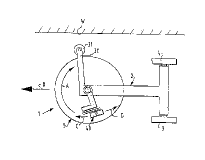
fig. 1 shows a principal diagram of an apparatus
according to the present invention;
fig. 2 shows a perspective view partly broken away of
the embodiment of fig. 1; and
fig. 3 shows a perspective view of an alternative
part
of the embodiment of fig. 2.
An apparatus 1 (fig. 1) comprises a chassis or frame 2,
from which two non-driven rear wheels 3, 4 are suspended
and a substantially horizontal wheel or disk 5 which is
driven in the direction of arrow A. To prevent the disk or
wheel 5 damaging a wall W, the apparatus is preferably
provided with a frame part 30 projecting beyond the
circumference of the disk and on which a freely rotatable
wheel 31 is disposed.
The wheel or disk 5 exerts angular momentum relative to
the pair of rear wheels in the direction of arrow A to the
surface to be processed, whereby the surface exerts angular momentum in the
opposite direction to the apparatus, which results in a
tendency of a deflection to one side. This can therefor be
undesirable especially in the present embodiment where the
rear wheels 3, 4 are not driven. To prevent this
undesirable momentum, a pressing member 40 is disposed on
frame 2, which obviates or reduces the angular momentum
and converts it into a force in the forward direction of
arrow B, which force also facilitates pushing the
apparatus. As the pressing member 40 is displaceable in
the direction of the arrows C and D, according to the
preferred embodiment of the apparatus according to the
present invention, the position of the pressing force is

CA 02194949 2000-OS-16
C 7413 (V)
4
adjustable relative to the disk, whereas the magnitude of
the reaction angular momentum exerted by the surface to the
apparatus and the magnitude of the propelling force are
also adjustable, If on e.g. a rough surface of the floor the
pressing member is displaced in the direction of arrow D,
the forward force is decreased, while the tearing to the
side of the apparatus is reduced to a sufficient extent.
When adjusted in the direction of arrow C, the forward
force increases and the angular momentum of the surface to
the apparatus decreases. '
The wheel 5, in this embodiment formed by a spoked wheel
and a closed diskshaped plate, is driven by a belt or
string 12, which is bound around pulleys 10 and 11 and
which is driven through a further belt around pulleys 8
and 9, one of which is driven by an electric motor 7.
Pulley 11 is disposed on a pivotable support part 13, and
tension spring 14 maintain the tension in belt 12.
Preferably the apparatus is provided with a precharcheable
battery, so that an electric cable can be dispensed with
during the operation.
Wheel 5 and disk 6 are attached to the frame by means of a
cardanic suspension 15 which is disposed on a suspension
frame part 16, whereby wheel 5 and disk 6 are movable in
all directions, at least in the pivot direction imposed by
pressing member 40.
Pressing wheel 20 is pivotably disposed on a suspension
part 22 via arm 21, which suspension part 22 is secured to
the cardanic suspension 15. The pressing force of the
pressing wheel 20 can be varied by screwing of a counter
weight 23 which is provided on a further arm 24 to pivot
axis 25. Pressing wheel 20 is in the present embodiment
formed by a wear-resistant wheel of plastic material.

C 7 41,3 ,~ V )
21 ~49'~9
The position of the pressing wheel 20 is adjustable along
the circle arc of arrows C and D by means of an adjusting
knob 26 which can be arrested e.g. in a depressed rest
position, and which will displace a toothed rack 28,
5 according to the circle arc through toothed pinion 27,
when it is lifted and turned.
In practice the user will primarily adjust the position of
the pressing wheel of the disk dependent on the
roughness/smoothness of the surface to be scrubbed or
polished and dependent on the type of scrub element or
polishing element present under the disc, as this biasing
can be executed easily from the exterior. Since biasing
the magnitude of the pressing force will have to be done
in the interior of the apparatus e.g. by screwing and
displacing of the counter weight, this type of adjustment
is less preferred in actual practice.
In a non shown way, the apparatus is preferably provided
with a central driven wheel for driving the apparatus.
It goes without saying that the present invention is not
limited to the above described preferred embodiment there-
of. The requested rights are primarily defined by the
following claims, within the scope of which various
modifications are possible.
A variation which is not limited, relates e.g. to the way
in which the force exerted by the pressing wheel to the
disc is adjusted. As shown in figure 3, this force can
also be adjusted through a screw spring 51 which can be
adjusted by turning knob 52.

Representative Drawing
A single figure which represents the drawing illustrating the invention.
Administrative Status

2024-08-01:As part of the Next Generation Patents (NGP) transition, the Canadian Patents Database (CPD) now contains a more detailed Event History, which replicates the Event Log of our new back-office solution.

Please note that "Inactive:" events refers to events no longer in use in our new back-office solution.

For a clearer understanding of the status of the application/patent presented on this page, the site Disclaimer , as well as the definitions for Patent , Event History , Maintenance Fee  and Payment History  should be consulted.

Event History

Description Date
Inactive: IPC expired 2024-01-01
Time Limit for Reversal Expired 2010-01-13
Letter Sent 2009-01-13
Inactive: IPC from MCD 2006-03-12
Letter Sent 2003-09-05
Grant by Issuance 2001-03-13
Inactive: Cover page published 2001-03-12
Pre-grant 2000-12-07
Inactive: Final fee received 2000-12-07
Letter Sent 2000-07-06
Notice of Allowance is Issued 2000-07-06
Inactive: Approved for allowance (AFA) 2000-06-13
Amendment Received - Voluntary Amendment 2000-05-16
Inactive: S.30(2) Rules - Examiner requisition 1999-11-22
Amendment Received - Voluntary Amendment 1998-07-08
Inactive: Application prosecuted on TS as of Log entry date 1998-03-18
Letter Sent 1998-03-18
Inactive: Status info is complete as of Log entry date 1998-03-18
All Requirements for Examination Determined Compliant 1997-09-11
Request for Examination Requirements Determined Compliant 1997-09-11
Application Published (Open to Public Inspection) 1997-08-09

Abandonment History

There is no abandonment history.

Maintenance Fee

The last payment was received on 2000-12-15

Note : If the full payment has not been received on or before the date indicated, a further fee may be required which may be one of the following

  • the reinstatement fee;
  • the late payment fee; or
  • additional fee to reverse deemed expiry.

Patent fees are adjusted on the 1st of January every year. The amounts above are the current amounts if received by December 31 of the current year.
Please refer to the CIPO Patent Fees web page to see all current fee amounts.

Owners on Record

Note: Records showing the ownership history in alphabetical order.

Current Owners on Record
UNILEVER PLC
JOHNSONDIVERSEY, INC.
Past Owners on Record
DIETER WINDMEISSER
Past Owners that do not appear in the "Owners on Record" listing will appear in other documentation within the application.
Documents

To view selected files, please enter reCAPTCHA code :


To view images, click a link in the Document Description column (Temporarily unavailable). To download the documents, select one or more checkboxes in the first column and then click the "Download Selected in PDF format (Zip Archive)" or the "Download Selected as Single PDF" button.

List of published and non-published patent-specific documents on the CPD .

If you have any difficulty accessing content, you can call the Client Service Centre at 1-866-997-1936 or send them an e-mail at CIPO Client Service Centre.

({010=All Documents, 020=As Filed, 030=As Open to Public Inspection, 040=At Issuance, 050=Examination, 060=Incoming Correspondence, 070=Miscellaneous, 080=Outgoing Correspondence, 090=Payment})


Document
Description 
Date
(yyyy-mm-dd) 
Number of pages   Size of Image (KB) 
Abstract 1997-04-28 1 14
Description 1997-04-28 5 206
Drawings 1997-04-28 2 62
Claims 1997-04-28 3 52
Abstract 2000-05-15 1 16
Description 2000-05-15 5 228
Claims 2000-05-15 1 43
Representative drawing 1997-11-25 1 5
Representative drawing 2001-01-29 1 5
Acknowledgement of Request for Examination 1998-03-17 1 179
Reminder of maintenance fee due 1998-09-14 1 115
Commissioner's Notice - Application Found Allowable 2000-07-05 1 162
Maintenance Fee Notice 2009-02-23 1 171
Correspondence 1997-02-10 4 153
Correspondence 2000-12-06 1 33