Note: Descriptions are shown in the official language in which they were submitted.
CA 02195060 2005-02-16
25644-17
- 1 -
tTNIVERBAL NON-POROUS FIBER REINFORCED COMBIISTION CHHAMBER
BACKGROUND OF THE INVENTION
1. Field of the Invention
The present invention relates to a universal
combustion chamber useful for installation in metal
fabricated fireplaces or a.stand alone combustion chamber.
More particularly, the present invention relates to an=
assembled non-porous cast fiber-reinforced combustion
chamber that is machinable in its cured stage and moldable
in its uncured preformed stage.
2. Description of t,l~e]Rrior Art
Heretofore, panels made.from high temperature
ceramic materials were known. Heat-N-GlowYMof Savage,
Minnesota has incorporated high temperature ceramic panels
under the gas burners of some of their gas fireplaces in the
YM
form of loose panels. Heat-N-Glow has also incorporated
both refractory firebrick and cast ceramic blocks or . panels
in numerous stoves and fireplaces for insulation purposes as
well as for aesthetic purposes.
Manufacturers of commercial and home heating
systems have employed cast refractory fireboxes in the base
of furnaces. Such refractory fireboxes are protected
against exhaust leakage because they are placed in an area
2195060
- 2 -
where leakage would not escape from the furnace or boiler or
are completely backed up by another non-porous sheet or
wall.
Unvented or non-vented gas heaters and fireplaces
are not concerned with preventing escape of burned exhaust
gasses into a living area, thus, do not totally enclose the
combustion chamber or burners. Such unvented gas stoves
have been known to deplete the oxygen supply in a living
area.
Applicants are not aware of any gas fireplace
%
which employs a gas combuStion chamber that virtually
eliminates the need for any fireplace enclosure or shroud
around the gas combustion chamber for heat protection.
It would be desirable to provide a universal
combustion chamber which would accommodate a variety of gas
burners and a variety of vents. It would further be
desirable to provide an assembled leak proof combustion
chamber made from non-porous cast fiber reinforced moldable
and machinable material that is cool enough at its outer
surface to be installed without additional insulation or
heat protective barriers on the outside of the combustion
chamber.
SUMMARY OF THE INVENTION
It is a principal object of the present invention
to provide an assembled gas fireplace combustion chamber
2195060
- 3 -
that comprises a plurality of non-porous cast fiber
reinforced panels.
It is another principal object of the present
invention to provide a fabricated kit of non-porous cast
fiber reinforced panels that are accurately formed to be
assembled into a leak proof fireplace combustion chamber.
It is another principal object of the present
invention to provide an assembled prefabricated non-porous
cast fiber reinforced combustion chamber that is machined
and ready for installatior~ of a gas burner.
It is another principal object of the present
invention to provide a-plurality of assembled or unassembled
machined non-porous cast fiber reinforced panels that when
assembled form a combined combustion chamber and fireplace
ready for completion by addition of a gas burner and/or a
gas vent.
It is yet another object of the present invention to
provide a universal gas combustion chamber/fireplace unit
that does not require a metal enclosure for operation in a
fireplace.
It is yet another principal object of the present
invention to provide a universal gas combustion chamber/
fireplace unit that is operable with a gas burner and has an
outer wall temperature cool enough to meet standards for
zero clearance installations.
CA 02195060 2006-09-29
25644-17
- 4 -
It is another object of the present invention to
lower the cost of manufacturing gas fireplace units while
increasing their efficiency by combining the functions
normally associated with a separate gas combustion chamber
and fireplace enclosure.
According to these and other objects of the
present invention there is provided a universal gas
combustion chamber of the type having a bottom floor panel,
a top panel and vertical side panels assembled to form a
fireplace when a gas burner is installed in or on the floor
panel. Said gas combustion chamber panels being made from a
moldable slurry of refractory ceramic fibers (preferably
vitreous alumina silicate fibers) and a binder (preferably
amorphous silica) to form strong machinable fiber reinforced
panels.
According to a broad aspect of the present
invention, there is provided a method of making a universal
gas combustion chamber for use in a plurality of different
prefabricated gas fireplace units, comprising the steps of:
mixing refractory ceramic fibers (RCFs) with a solution of
inorganic amorphous silica binder to form a thick paste
slurry, pouring said thick paste slurry into a mold for an
open box shape fireplace having a plurality of panels
comprising a floor panel, at least two side panels and a top
panel, drying the open box shaped fireplace in its mold,
removing said open box shaped fireplace from its mold,
firing said panels to form a non-porous impact resistant
open box of panels of a gas fireplace combustion chamber,
assembling stack means, trim means, burner means, a door and
said plurality of panels into the gas fireplace combustion
chamber to provide said different gas fireplace units, and
sealing the joints between said stack means and said trim
CA 02195060 2006-09-29
25644-17
- 4a -
means, to form unique fireplace units having a reinforced
non-porous gas tight gas combustion chamber.
According to another broad aspect of the present
invention, there is provided a universal open box combustion
chamber for use in a plurality of different types of
fireplaces comprising, a floor panel, a top panel, two side
panels, said floor panel, said top panel said side panels
each comprising a mixture of vitreous alumina silicate
fibers and an aqueous solution of inorganic amorphous silica
binder formed and dried, in a mold after pouring in a mold
and molding, and fired to provide a gas tight and impact
resistant box of panels of a fireplace combustion chamber,
glass door means and a back panel means attached to said
panels to provide a gas tight closed box fireplace, and
burner means supported by said floor panel.
According to still another broad aspect of the
present invention, there is provided a method of making a
universal gas combustion chamber for use as a component of a
fireplace unit, comprising the steps of: mixing vitreous
alumina fibers with an aqueous solution of inorganic
amorphous silica binder to form a thick castable slurry,
forming said thick castable slurry on a forming mold to
build up a desired predetermined thickness non-rigid
fireplace combustion chamber having an open side for
supporting door means and a floor for supporting a gas
burner, drying said formed combustion chamber on the mold to
provide an uncured stiff one piece combustion chamber,
stripping away the forming mold, and heating said uncured
one piece combustion chamber at firing temperature to form a
rigid non-porous impact resistant combustion chamber ready
for assembly of said door means and gas burner to form a
unique fireplace.
CA 02195060 2005-02-16
25644-17
- 4b -
BRIEF DESCRIPTION OF THE DRAWINGS
Figure 1 is a section in side elevation taken
through a novel assembled non-porous cast ceramic fiber
combustion chamber having a burner opening in the floor
panel and an exhaust opening in the top panel and installed
flush mounted as a vented gas fireplace;
Figure 2 is a front view of the vented fireplace
shown in Figure 1 showing a decorative surround with a
simulated brick pattern which compliments the pattern in the
interior of the non-porous cast ceramic combustion chamber;
2195060
- 5 -
Figure 3 is a section and side elevation taken
through a modified assembled ceramic combustion chamber
having a metal rear panel and a fireplace enclosure which
forms a heat exchanger around the bottom, back and top of
said combustion chamber;
Figure 4 is diagrammatic drawing in sectional plan
view of the combustion chamber of Figure 1;
Figure 5 is a diagrammatic drawing in sectional
plan view of a combustion chamber of Figure 3 showing a two-
level gas pipe gas burner therein;
Figure 6 is a front view of a vented fireplace
comprising the novel ceramic combustion chamber and a
fabricated metal base'support;
Figure 7 is a diagrammatic drawing in plan view
showing the base support of Figure 6;
Figure 8 is a front view of the base support of
Figure 6 and 7 with the front trim panel and transfer
support bar removed;
Figure 9 is a section in side elevation taken
through a modified assembled ceramic combustion chamber
completed for installation as a horizontal vented zero
clearance fireplace;
Figure 10 is a section in side elevation taken
through a modified assemble ceramic combustion chamber
completed for installation as a vertical vented zero
clearance fireplace;
2195060
- 6 -
Figure 11 is a diagrammatic isometric view of the
novel assembled non-porous cast ceramic combustion chamber
before modification for use as an unvented fireplace, a
vented fireplace or a direct vented fireplace with or
without a heat exchanger modification;
Figure 12 is a plan view of a floor or top panel
of a novel ceramic combustion chamber illustrating a second
preferred embodiment panel;
Figure 13 is a section taken at lines 13-13 of
Figure 12;
Figure 14 is a section as it would appear if taken
at lines 13-13 through a top panel when reverse oriented;
Figure 15 is an enlarged section in elevation
taken through a floor panel showing a preferred metal flat
pan burner;
Figure 16 is an enlarged -a~nd section in elevation
taken through a floor panel showing a non-porous ceramic
flat pan burner;
Figure 17 is an enlarged section in elevation
taken through a floor panel showing another non-porous
ceramic flat pan burner;
Figure 18 is an enlarged section in elevation
taken through a floor panel showing a composite metal/non-
porous ceramic flat pan burner;
2195060
- 7 -
Figure 19 is an enlarged detail of a vertical
joint formed by a side and a rear panel of a ceramic
combustion chamber having three vertical panels;
Figure 20 is an enlarged detail of a another
vertical joint formed by a separate side and rear panel; and
Figure 21 is a block diagram showing the steps
preferably employed to form the panels used in the novel gas
combustion chamber described in the Figures hereinbefore.
DETAILED DESCRIPTION OF THE PREFERRED EMBODIMENTS
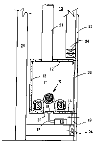
Refer now to Figure 1 showing a vented gas
fireplace unit 10 in side elevation taken through the novel
assembled non-porous cast ceramic fiber combustion chamber
11. The combustion chamber 11 comprises a top panel 12, -a
rear panel 13 and a bottom or floor panel 14. The floor
panel 14 is provided with an aperture 20 in which a flat pan
gas burner 15 is placed either below or at the surface of
the floor panel 14. The flat pan burner 15 is shown
connected to a gas valve 16 via a gas connection pipe 17.
Air for combustion at the gas burner 15 enters through the
louvered cover 19 and passes as burning gas around the logs
18 and is exhausted through the exhaust stack 21. A glass
front panel 22 may be provided on the vented gas fireplace
unit 10 or may be removed if so desired. A decorative
surround panel 23 formed as a simulated brick mantel piece
is mounted directly to the studs 24 which are used to form a
chase or enclosure around the combustion chamber.
2195060
- 8 -
Refer now to an enlarged front view of the vented
fireplace 10 shown in Figure 1. The decorative surround
panel 23 is provided with an aperture in which the
combustion chamber 11 is placed. The combustion chamber 11
is further provided with a decorative brass trim 25 which
complements the surround panel 23. The panel 13 in the back
and side of the combustion chamber 11 is shown having a
simulated brick embossed surface which complements the
surround panel 23.
Refer now to Fig'
yre 3 showing a side elevation
taken through a modified assembled ceramic combustion
chamber which.has a metal rear panel 29. The metal rear
panel and the rear panel 28 of a fireplace enclosure form a
heat exchanger rear wall 31. A similar heat exchanger wall
27 is formed between the top panel 12 and the top metal
panel of the fireplace enclosure 26. A bottom heat
exchanger wall 32 is formed between the bottom or base of
the fireplace unit 10 and the bottom or floor panel 14. A
blower 33 is installed in the bottom wall 32 of the
fireplace unit and moves air from the outside room through
walls 32, 31 and 27 to form a heat exchanger for the
combustion chamber 11. A baffle 34 is shown in installed in
the upper and rear portion of the combustion chamber 11 to
increase the exhaust gas flow and efficiency to the heat
exchanger.
2195060
- 9 -
Refer now to Figure 4 showing a diagrammatic
drawing in sectional plan view of the combustion chamber 11
of Figure 1. The aforementioned rear panel 13 and the side
panels 35 and 36 are preferably made from a non-porous cast
fiber reinforced insulating material which will be described
in greater detail hereinafter. The combustion chamber 11 is
shown assembled from panels 13, 35 and 36 and the floor
panel 14 before the top panel 12 is assembled and not shown.
Corner brackets 37 and 38 are preferably provided at the
sharp edges of the combustion chamber 11 to provide corner
reinforcements. The corrier brackets 37 and 38 are
preferably attached to the combustion chamber 11 with high
temperature adhesives. However, it will be understood that
ordinary silicon caulking compound which is durable up to
500 degrees Fahrenheit may also be used as an adhesive to
attach the corner brackets 37 and 38. The aperture 20
through which the flat pan burner 15 is installed is shown
in the rear and center of the combustion chamber 11. It
will be understood that other types of apertures and other
types of burners may be used within the universal combustion
chamber 11 as will be explained hereinafter.
Refer now to Figure 5 showing a diagrammatic
drawing in sectional plan view of the combustion chamber of
Figure 3. The combustion chamber 11 in this drawing is
shown provided with a two-level pipe burner 39 and an
appropriate aperture for a combustion gas pipe will be
2195060
- 10 -
provided in the floor or bottom panel 14. The side walls 35
and 36 are preferably abutted against the rear panel 29 of
the heat exchanger and is overlapped by the back panel 28 or
the back wall of the fireplace enclosure 28. These panels
may be attached with high mechanical fasteners because the
heat which passes through the panel 29 is intended to be hot
enough to serve as a heat exchanger for the back wall 31 as
explained hereinbefore.
Refer now to Figure 6 showing a front view of a
vented fireplace which comprises the aforementioned novel
ceramic combustion chamber 11 which comprises two side walls
35 and 36, a top wall 12, a bottom wall 14 and a rear wall
13. The edges of the aforementioned walls 43 are shown
exposed but may have attached thereto either decorative trim
or surround pieces as described hereinbefore. The
combustion chamber 11 is further provided with a fabricated
metal base 41 onto which a trim piece or closure piece 42 is
attached. A baffle 34 is installed in the combustion
chamber 11 and supported therefrom by means not shown. The
stack 21 is shown attached to the combustion chamber by
means of a collar 44 and screws 45. It will be understood
that the fiber reinforced ceramic material is thick enough
and dense enough to accept conventional screws for
attachment purposes.
Refer now to Figure 7 showing a diagrammatic
drawing in plan view of the base support 41. The base
2195060
- 11 -
support 41 is preferably formed from a single piece or'three
pieces of sheet metal to form an enclosure or surround which
nests at the outer edges of the floor or bottom panel 14.
In the preferred embodiment of the present invention, a
transverse support bar 46 is provided between the two side
panels of the base support 41 and used to support the
aforementioned gas valve 16 and flat pan burner 15.
Refer now to Figure 8 showing a front view of the
base support 41 and support tabs 47 which are formed by
piercing tabs from the panel metal and diverting it from a
~
vertical axis into a horizontal axis by bending the tab
inward. The front of the metal base 41 may be closed by the
trim piece 42 or the triin piece 42 may be made in the form
of a louver for access air. However, by making the tabs 47
from the parent panel metal, air is capable of passing
through the apertures made when the support tabs are formed.
Refer now to Figure 9 showing a section in side
elevation through a modified assembled ceramic combustion
chamber 11 which is completed for installation as a
horizontal direct vented zero clearance fireplace. The
numerals used in the previous figures which are
substantially the same as those employed in Figure 9 are
number the same and do not require additional description.
The fireplace 11 is shown provided with a horizontal stack
48 which is adapted to fit onto the rear of the rear panel
13 of the combustion chamber 11 by a collar 49. Surrounding
2195060
- 12 -
the collar 49 is a combustion air chamber 51 which extends
downward along the back of the rear panel 13 and forms a
plenum 52 for providing a fresh air passageway into the
bottom of the combustion chamber through either into the
wall 32 or through an aperture 53 into the combustion
chamber 11. It will be understood that the plenum 52 shown
along the back of the rear panel 13 may be formed as a duct
which enters the bottom or the sides of the combustion
chamber 11 but still forms a duct for communicating fresh
combustion air into the coiabustion chamber.
Refer now to Figure 10 showing a side elevation
taken through a modified assembled ceramic combustion
chamber completed for installation as a vertical zero
clearance fireplace. The aforementioned plenum 52 is shown
as a plenum 54 which also passes down the rear of the rear
panel 13 of the combustion chamber 11 and communicates with
the rear or bottom of the combustion chamber 11 at panel 14.
In the preferred embodiment of the present invention, it is
desired to bring the fresh combustion air down below the
floor panel 14 and to permit it to rise along the edges of
the flat pan burner 15 so as to effect a more complete
combustion and flame color around the decorative logs 18.
The vertical stack 21 is adapted to the combustion chamber
11 by a collar 49 and the plenum or passageway 54 is formed
from sheet metal and attached to the top and rear of the
panels 12 and 13 of the combustion chamber 11. The numerals
2195060
- 13 -
in the Figure 10 are the same as those employed in Figiire 9
and do not require additional explanation.
Refer now to Figure 11 showing an isometric view
of a novel assembled non-porous cast ceramic combustion
chamber 11 before modification for use as an unvented
fireplace or as a vented fireplace or as a direct vented
fireplace with or without a heat exchanger modification.
The novel combustion chamber shown in Figure 11 is
preferably made from an alumina silicate fiber solution, or
an equivalent, with a bind-r and mixed to agitate the fibers
to absorb the solution. fOnce the mixture of fibers forms a
slurry as thick as a paste, it may be molded into any
desired shape. The trapezoidal flat panel shape shown in
Figure ll is a preferred embodiment. However, the top and
bottom panels may be made as a segment of a circle and the
side walls 35, 36 and 13 may be made as a continuous curved
panel. In any event, it is desired that the novel
combustion chamber 11 be assembled from at least three
pieces. The advantage to employing substantially flat
panels is to enable one to ship the novel gas combustion
chamber in a knock down kit easily packaged package for a
minimum of transportation cost.
Refer now to Figure 12 showing a plan view of a
floor or top panel of a novel ceramic combustion chamber
illustrating a second preferred embodiment panel. The panel
14 shown in Figure 12 is provided with grooves 55 which will
2195060
- 14 -
accept and precision locate the aforementioned side panels
35, 36 and the rear panel 13.
Refer now to Figure 13 showing a section taken at
lines 13-13 of Figure 12 and showing the aforementioned
groove 55 which will accept a side panel 36 and precision
locate it therein. Similarly, a groove 56 is shown in
Figure 14 which is identical to the groove 55 shown in
Figure 13. When the panel 14 is reversed 180 degrees, the
groove on the left side of the lower panel becomes the
groove on the right side for the upper panel.
/
Refer now to Figure 15 showing an enlarged section
in elevation taken through a floor panel 14 showing a
preferred embodiment metal flat pan burner 15 located in an
aperture 20 which is preferably formed by cutting dies.
Refer now to Figure 16 showing an enlarge section
in elevation taken through a floor panel 14 showing a non-
porous ceramic flat pan burner 57 formed by drilling gas
port apertures 58 into the floor panel 14 and providing air
access slots 59 adjacent thereto. In the preferred
embodiment shown in Figures 16, the lower portion of the
flat pan burner is formed by non-porous ceramic fiber
reinforced material the same as a metal flat pan burner and
the bottom portion 61 has the same interior spacing as a
flat pan burner 15 so as to provide the same gas
distribution within the flat pan burner as before. The
lower portion of the flat pan burner 57 is preferably
2195060
- 15 -
attached to the lower or bottom panel 14 by mechanical'
attachment means as well as adhesives.
Refer now to Figure 17 showing an enlarged section
in elevation taken through a floor panel 14 which has
machined therein the interior dimensions of a flat pan
burner 15 shown as the area 62. Gas ports 63 are drilled or
punched in the panel 14 opposite the lower pan portion 64
which is attached to the bottom panel 14 by mechanical and
adhesive means and provided with air slots 65 extending
through both parts 64 and 14.
/
Refer now to Figure 18 showing an enlarged section
in elevation taken through a floor panel 14 showing a
composite metal and non-porous ceramic flat pan burner. The
upper portion of the flat pan burner is similar to that
described with reference to Figure 17 and is provided with
gas ports 63 which communicate with a lower metal pan
portion of a gas pan burner 66. Air slots 65 are provided
through the panel 14 to provide combustion air for the
burner 66.
Refer now Figure 19 showing an enlarged detail of
a vertical joint formed by a side panel 35 and a rear panel
13 held together by a corner support bracket 37 which is
preferably attached with a high temperature adhesive or even
a silicone caulking compound.
Refer now to Figure 20 showing in enlarged detail
of another vertical joint formed by a side panel 35 and a
CA 02195060 2005-02-16
25644-17
- 16 -
.rear panel 13 which are held together by axeinforcing.,
spline 67. Again, it is preferred that the panels be closed-
with a high temperature cement to assure that they are
exhaust gas leak proof.
Refer now to Figure 21 showing a block diagram of
the steps employed to make a moldable and castable slurry or
paste of reinforced ceramic fibers used to make panels which
are used to assemble the novel universal gas combustion
chambers. In block 69 fibers of alumina silicate are mixed
with a binder solution which is in aqueous form. The
preferred aqueous solution is a binder of amorphous silicate
which may be purchased from Nalco Chemical Company in
Naperville, IL under the.designation Na1coM1140. The high
temperature reinforced fibers preferably are made from a
mixture of silica and alumina (Si02 and A1203) which are
mixed and then melted and formed as fibers by blowing drops
or portions of the melted mixture to form fibers that are
graded by length and preferably are in a form of 1/2 to 1-
1/2 inches in length when mixed with amorphous silica.
After the combination of fibers and binder solution are
mixed together, they are agitated.so that the fibers
completely absorb the binder solution as shown in block 70..
After the mixing and agitation occurs, a slurry or paste is
formed as shown in block 71 which is of a consistency which
permits pouring or filling into molds or casting
receptacles. The slurry or paste is then molded or cast or
2195060
- 17 -
formed into this desired shape as shown in block 72. The
molding and casting of a desired shape of the paste may be
formed on a continuous line in a flat panel form in which
case the material is passed into a drying oven and would not
require removal from a mold as shown in block 73. The step
performed at block 73 could be a progressive stamping mold
or a rotary mold. After the material passes from the
molding or casting operation at block 73, it is dried as
molded panels by firing or by holding in heated molds to dry
off the water from the green paste mold. In the preferred
embodiment, firing is accomplished at temperatures between
350 degrees Fahrenheit up to 1800 degrees Fahrenheit to
drive off the water solution which comprises up to 25s by
weight.
After drying or firing the panels at block 74, the
panels are trimmed or machined to a preliminary shape or
trimmed or machined to a final shape at block 75. Apertures
and slots and gas ports and burners are formed therein,
depending on the intended use of the panel. It will be
appreciated that in some forms of individual molds, the
edges of the dried panels are so precise that they do not
require machining when being fitted together to form an
assembled gas combustion chamber. After forming the desired
panels in the desire shapes with the desired slots, holes
and burners which may be formed by drilling or punching, the
panels may be assembled into a combustion chamber shown in
2? 95060
- 18 -
block 76 if the production operation is a continuous
operation. However, if the panels to be assembled into a
combustion chamber are for assembly at a production site or
installation site, it is preferred that individual kits be
manufactured from which assembled combustion chambers may be
made on site to assure minimum damage and minimum cost of
shipping. Thus, the desired panels for a particular
preformed gas combustion chamber are packaged as a set of
preformed parts for shipment as shown in block 77.
Having explaine d.-a preferred embodiment of the
present invention used irt several different types of
fireplaces, it will be appreciated that use of a universal
combustion'chamber greatly reduces the factory inventory as
well as the field site inventory of combustion chambers.
The fired and dried fiber reinforced combustion chamber is
slightly hydroscopic but non-porous to exhaust gases and may
be sealed without a steel or reinforcing backing layer even
when used for burning wood logs. The reinforced panel can
be made thicker and stronger for wood logs so as to meet
wood stove standards and impact tests performed by
underwriters as well as meeting zero clearance outside
temperature of 160 F if needed.
Manufacturers of Refractory Ceramic Fibers (RCFs)
and aqueous binders publish data sheets on several different
RCF. While the exact formulation may differ, the preferred
silicate base is vitreous alumina silicate for making high
2195060
- 19 -
temperature ceramic fibers. An equivalent silicate fiber
would be operable when combined with a compatible RCF
binder.