Language selection

Search

Patent 2195081 Summary

Third-party information liability

Some of the information on this Web page has been provided by external sources. The Government of Canada is not responsible for the accuracy, reliability or currency of the information supplied by external sources. Users wishing to rely upon this information should consult directly with the source of the information. Content provided by external sources is not subject to official languages, privacy and accessibility requirements.

Claims and Abstract availability

Any discrepancies in the text and image of the Claims and Abstract are due to differing posting times. Text of the Claims and Abstract are posted:

  • At the time the application is open to public inspection;
  • At the time of issue of the patent (grant).
(12) Patent Application: (11) CA 2195081
(54) English Title: CAR CRASH PROTECTOR
(54) French Title: PARE-BUFFLE POUR VEHICULE
Status: Deemed Abandoned and Beyond the Period of Reinstatement - Pending Response to Notice of Disregarded Communication
Bibliographic Data
(51) International Patent Classification (IPC):
  • B60R 19/52 (2006.01)
(72) Inventors :
  • VERMEULEN, JAN WILLEM
(73) Owners :
  • KELOWNA HECTARES B.V.
(71) Applicants :
  • KELOWNA HECTARES B.V.
(74) Agent: SMART & BIGGAR LP
(74) Associate agent:
(45) Issued:
(86) PCT Filing Date: 1995-07-17
(87) Open to Public Inspection: 1996-02-01
Examination requested: 2002-03-26
Availability of licence: N/A
Dedicated to the Public: N/A
(25) Language of filing: English

Patent Cooperation Treaty (PCT): Yes
(86) PCT Filing Number: PCT/NL1995/000250
(87) International Publication Number: NL1995000250
(85) National Entry: 1997-01-14

(30) Application Priority Data:
Application No. Country/Territory Date
9401181 (Netherlands (Kingdom of the)) 1994-07-18

Abstracts

English Abstract


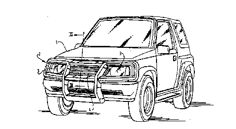
The invention relates to a device for fixing to the front part of a vehicle,
comprising a support construction which is assembled from profile parts
manufactured from metal plate material and provided with attachment points for
fixing thereof to the vehicle, a plastic cover element for separately covering
the sides of each profile part facing away from the vehicle and means for
connecting the cover element to the support construction, wherein between the
profile parts of the support construction and the cover element free spaces
are present and the cover element is manufactured from deformable plastic.


French Abstract

Dispositif adapté pour se fixer à la partie avant d'un véhicule et constitué d'une structure de support assemblée à partir de profilés fabriqués à partir de plaques métalliques, et pourvue de points de fixation permettant sa fixation au véhicule, d'un élément de couverture en matière plastique servant à recouvrir indépendamment les faces de chaque profilé qui sont tournées vers l'extérieur, et d'un ensemble de fixation de l'élément de couverture à la structure de support, des espaces vides étant présents entre les profilés de la structure de support et l'élément de couverture, et ledit élément de couverture étant en matière plastique déformable.

Claims

Note: Claims are shown in the official language in which they were submitted.


CLAIMS
1. Device for fixing to the front part of a vehicle,
comprising a support construction which is assembled from
profile parts manufactured from metal plate material and
provided with attachment points for fixing thereof to the
vehicle, a plastic cover element for separately covering the
sides of each profile part facing away from the vehicle and
means for connecting the cover element to the support
construction, wherein between the profile parts of the
support construction and the cover element free spaces are
present and the cover element is manufactured from deformable
plastic.
2. Device as claimed in claim 1, characterized in that
the free spaces are located on the sides of the profile parts
located at the greatest distance from the vehicle.
3. Device as claimed in claim 1 or 2, characterized in
that the support construction is connected to the vehicle
with interposing of at least one element absorbing energy
during deformation.
4. Device as claimed in claim 3, characterized in that
the energy-absorbing element is a deformable mounting
bracket.
5. Device as claimed in claim 3, characterized in that
the energy-absorbing element is a spring.
6. Device as claimed in any of the foregoing claims,
characterized in that the parts of the cover element located
closest to the sides of the vehicle project over the support
construction.

Description

Note: Descriptions are shown in the official language in which they were submitted.


WO 96/02406 PCT/N19!;/00250
., 1! !~ 1
2t95381
CaK CRASH r~-,~uL~K
~ he invention relates to a device for fixing to the
front part of a vehicle.
Existing constructions for fixing to the front side of
a vehicle usually consist of a grid structure or bar assembly
to protect the front part of the vehicle. The cul.~LLu~Lion
must protect the vehicle against for example wildlife, stray
cattle, branches etc, and is generally attached to cross-
country vehicles or types of vehicles derived therefrom.
Such a construction is a functionally superfluous
attribute for vehicles on the public highway but contri~utes
' to a particular image of the vehicle to which it is fixed.
Many ~l~LUSs coulltry vehicles" are only used in an environment
where a car crash protector is functionally superfluous, but
wherein a car crash protector is ; n~ i~p~n~hle to the image
of the vehicle. For fellow road-users (for instance
pedestrians or cyclists) the danger of serious injury i8
increased in the case of a collision with such a "cross-
country vehicle".
The object of the present invention is to manufacture a
construction for fixing to the front part of a vehicle,
without adversely affecting the appearance of the
construction, such that the danger of "serious" injury to
fellow road-users is limited.
The invention provides to this end a device for fixing
to the front part of a vehicle comprising a support
construction which is assembled from profile parts
manufactured from metal plate material and provided with
attachment points for fixing thereof to the vehicle, a
plastic cover element for separately covering the sides of
each profile part facing away from the vehicle and means for
~connecting the cover element to the support ~ul.~LLu~Lion,
wherein between the profile parts of the support ~onsLLu~Lion
and the cover element free spaces are present and the cover
element is manufactured from deformable plastic.

W096/02406 PCT~L95/00250
~ 2 2 ~ q 5 ~
The free spaces are preferably located on the side of
the profile parts located at the greatest distance from the
vehicle.
The thus manufactured construction has a robust
appearance but is also capable of ~h~orh; ng energy during a
collision. In the case of a light collision only the plastic
cover element of the construction will deform. After the
collision the cover element will then be able to reassume its
original form. In the case of a heavier collision not only
the plastic cover element cleforms but the support
construction manufactured from metal plate material also
deforms. This deformation is permanent but absorbs a
relatively large amount of energy, whereby an object involved
in the collision tfor instance a fellow road-user) will be
less badly damaged.
The support ~u..DLLuuLion is preferably connected to the
vehicle with interposing of at least one element absorbing
energy during deformation. In a preferred : -;r t the
energy-absorbing element is formed by a deformable mounting
bracket. In another preferred ' '; L the energy-~hqorhing
element is a spring. ~he energy-~hsorh; ng elements increase
the total capacity of the Pnergy-~hsorhing power of the
construction. This ~nh~nr~ the above stated advantages.
The parts of the cover element located closest to the
sides of the vehicle preferably project over the support
construction. The cover element is hereby not supported on
the sides by the support construction, whereby they will fold
over in the case of a collision.
The invention is further elucidated with reference to
the non-limitative : 'i- ts shown in the following
figures. ~erein:
fig. 1 shows a perspective view of a vehicle provided
with a car crash protector according to the invention,
fig. 2 is a pe-D~euLive view of a car crash protector~S ~ 9~ ' led into parts,
fig. 3 is a cross section through a part of the car
crash protector in the assemhled situation,
fig. 4a is a cross section through the car crash
protector in the assembled, non-deformed situation,
_ _

~096/02406 PcT~ns~oo~o
, 3 21 95~8l
fiy. 4b is a cross section through the car crash
protector as according to fig. 4a in temporarily deformed
situation,
fig. 4c iS a cross section through the car crash
protector as according to fig. 4a and 4b in p~rr-n~ntly
deformed situation, and
fig. 5 shows a cross section through an alternatively
embodied car crash protector.
Fig. 1 shows a vehicle 1, to the front side of which is
fixed ~ car crash protector 2. Car crash protector 2 is fixed
such that it leaves free the headlights 3 and the feed grill
4 for cooliny air. The car crash protector 2 provides vehicle
1 with a robust appearance.
Fig. 2 shows the car crash protector 2 in fl;qlqS~ d
parts. A cover element 5 manufactured from deformable plastic
can be connected to a metal support construction 7 using
connecting members 6. The support construction 7 is built up
of profile parts 8 made of relatively thin plate material.
Support cu.l~LLu~Lion 7 can be fixed to the vehicle 1 (not
shown here) using ~o~pl;ng elements 9. The upper two coupling
elements 9 shown here are provided with a weakened portion
10, whereby they are deformable. In the cover element 5 and
the support ~un~L~u~Lion 7 are arranged respective lecesses
11, 12 for insertion of the connecting members 6.
Fig. 3 shows in cross section a part of the car crash
protector 2 in assembled stnte. Shown clearly is a free space
13 which is situated on the front side between the cover
element 5 and the support ~llsLLu~Lion 7.
Fig. 4~ shows a cross section of the car crash
protector 2 of the foregoing figures in an llnln~d and
undeformed state. In fig. 4b the same cross section is shown
during a light collision. The plastic cover element 5 thereby
receives a dent 14 which is situated in the space 13 which
originally existed between cover element 5 and support
construction 7. The plastic cover element 5 can be '~';ed
such that a small dent 14 ~;q~ppe~rs again after a collision
because the d~f~ -' material springs back to the original
shape (see fig. 4a). Energy released during the collision is
herein absorbed by the deforming of cover element 5; the risk

wos6/0~06 PcTrNLssroo2so
~ t;jl'~; 4 2Iq 508
of injury toifellow road-users or damage to other objects is
hereby limited. Subsequently shown in fig. 4c is the
situation during a heavy callision. Not only the cover
element 5 but also the support ~ol-sLL~Lion 7 and the upper
coupling elements 9 are hereby deformed. The cover element 5
is not capable of Ahciorhing by means of a dent 15 all the
energy released during the collision. The ~ inin~ energy
will then be absorbed to an at least significant degree by
the deformation of the support construction 7. The plate
material of which the profi.le parts 8 of support c~ Ll~Lion
7 are made intentionally have a limited sturdiness so that
this generally permanent deformation becomes possible. Safety
is hereby further ~nhAnr~d,, since all energy ~h~orb~ by the
car crash protector 2 cannot damage a fellow road-user or
other object. Finally, the upper coupling elements 9 will
also deform close to the arranged weakened portions 10 so
that again a part of the energy is also hereby absorbed.
Fig. 5 shows a car crash protector 2, wherein the upper
coupling elements are formled by at least one spring 16. A
spring 16 is also capable of storing energy. After
compression of the spring 16 it can spring bac~ again into
the original position. This perhaps more expensive
construction therefore has the advantage that a possible
deformation of the mounting of car crash protector 2 to
vehicle 1 is only of a temporary nature.

Representative Drawing
A single figure which represents the drawing illustrating the invention.
Administrative Status

2024-08-01:As part of the Next Generation Patents (NGP) transition, the Canadian Patents Database (CPD) now contains a more detailed Event History, which replicates the Event Log of our new back-office solution.

Please note that "Inactive:" events refers to events no longer in use in our new back-office solution.

For a clearer understanding of the status of the application/patent presented on this page, the site Disclaimer , as well as the definitions for Patent , Event History , Maintenance Fee  and Payment History  should be consulted.

Event History

Description Date
Inactive: Dead - No reply to s.30(2) Rules requisition 2006-03-08
Application Not Reinstated by Deadline 2006-03-08
Deemed Abandoned - Failure to Respond to Maintenance Fee Notice 2005-07-18
Inactive: Abandoned - No reply to s.30(2) Rules requisition 2005-03-08
Inactive: Abandoned - No reply to s.29 Rules requisition 2005-03-08
Inactive: S.29 Rules - Examiner requisition 2004-09-08
Inactive: S.30(2) Rules - Examiner requisition 2004-09-08
Inactive: Application prosecuted on TS as of Log entry date 2002-04-09
Inactive: Status info is complete as of Log entry date 2002-04-09
Letter Sent 2002-04-09
Request for Examination Requirements Determined Compliant 2002-03-26
All Requirements for Examination Determined Compliant 2002-03-26
Letter Sent 1998-08-04
Reinstatement Requirements Deemed Compliant for All Abandonment Reasons 1998-07-24
Deemed Abandoned - Failure to Respond to Maintenance Fee Notice 1998-07-17
Letter Sent 1997-08-28
Deemed Abandoned - Failure to Respond to Maintenance Fee Notice 1997-08-26
Reinstatement Requirements Deemed Compliant for All Abandonment Reasons 1997-08-05
Application Published (Open to Public Inspection) 1996-02-01

Abandonment History

Abandonment Date Reason Reinstatement Date
2005-07-18
1998-07-17
1997-08-26

Maintenance Fee

The last payment was received on 2004-06-28

Note : If the full payment has not been received on or before the date indicated, a further fee may be required which may be one of the following

  • the reinstatement fee;
  • the late payment fee; or
  • additional fee to reverse deemed expiry.

Patent fees are adjusted on the 1st of January every year. The amounts above are the current amounts if received by December 31 of the current year.
Please refer to the CIPO Patent Fees web page to see all current fee amounts.

Fee History

Fee Type Anniversary Year Due Date Paid Date
Registration of a document 1997-02-21
MF (application, 2nd anniv.) - small 02 1997-07-17 1997-08-05
Reinstatement 1997-08-05
Reinstatement 1998-07-24
MF (application, 3rd anniv.) - small 03 1998-07-17 1998-07-24
MF (application, 4th anniv.) - small 04 1999-07-19 1999-07-06
MF (application, 5th anniv.) - small 05 2000-07-17 2000-06-28
MF (application, 6th anniv.) - small 06 2001-07-17 2001-06-27
Request for examination - standard 2002-03-26
MF (application, 7th anniv.) - standard 07 2002-07-17 2002-07-15
MF (application, 8th anniv.) - standard 08 2003-07-17 2003-06-26
MF (application, 9th anniv.) - standard 09 2004-07-19 2004-06-28
Owners on Record

Note: Records showing the ownership history in alphabetical order.

Current Owners on Record
KELOWNA HECTARES B.V.
Past Owners on Record
JAN WILLEM VERMEULEN
Past Owners that do not appear in the "Owners on Record" listing will appear in other documentation within the application.
Documents

To view selected files, please enter reCAPTCHA code :


To view images, click a link in the Document Description column (Temporarily unavailable). To download the documents, select one or more checkboxes in the first column and then click the "Download Selected in PDF format (Zip Archive)" or the "Download Selected as Single PDF" button.

List of published and non-published patent-specific documents on the CPD .

If you have any difficulty accessing content, you can call the Client Service Centre at 1-866-997-1936 or send them an e-mail at CIPO Client Service Centre.

({010=All Documents, 020=As Filed, 030=As Open to Public Inspection, 040=At Issuance, 050=Examination, 060=Incoming Correspondence, 070=Miscellaneous, 080=Outgoing Correspondence, 090=Payment})


Document
Description 
Date
(yyyy-mm-dd) 
Number of pages   Size of Image (KB) 
Representative drawing 1997-06-09 1 15
Abstract 1995-07-16 1 54
Description 1995-07-16 4 189
Claims 1995-07-16 1 35
Drawings 1995-07-16 3 114
Courtesy - Abandonment Letter (Maintenance Fee) 1997-08-25 1 188
Notice of Reinstatement 1997-08-27 1 172
Courtesy - Abandonment Letter (Maintenance Fee) 1998-08-03 1 189
Notice of Reinstatement 1998-08-03 1 172
Reminder - Request for Examination 2002-03-18 1 119
Acknowledgement of Request for Examination 2002-04-08 1 180
Courtesy - Abandonment Letter (R30(2)) 2005-05-16 1 165
Courtesy - Abandonment Letter (R29) 2005-05-16 1 165
Courtesy - Abandonment Letter (Maintenance Fee) 2005-09-11 1 173
Fees 1997-08-04 1 35
PCT 1997-01-13 8 328
Correspondence 1997-02-17 1 38
Fees 1997-08-25 4 320