Note: Descriptions are shown in the official language in which they were submitted.
WO 96/03?75 ~ ~ ~ ;~ PCTIGB95/O1?10
1
Method and Apparatus for A~~ng Spheres to a Foil Matrix
FIELD OF THE INVENTION
This invention generally relates to the fabrication of semiconductor devices
to
produce a solar cell and speafically to a method and apparatus for aff~ng
semiconductor members to a fail matrix.
BACKGROUND OF THE INVENTION
A number of systems for converting sunlight to electricity are known. One such
system that has proven useful in efficiently producing electricity from the
sun s
radiation is described in U.S. Patent No. 4,691,076. In that s3~stem, an array
is
formed of semiconductor particles or spheres. Each sphere has a ~p-type
interior and
an n-type skin. A plurality of the spheres are held in a matrix which includes
a pair
of aluminum foil members which form the contacts to the p-type and n-type
regions.
The foils are elecfrically insulated from one another and are flexible.
Multiple
flexible and conformable arrays can be electrically interconnected to form a
module
of solar cell elements for converting sunlight or other forms of photon energy
into
electricity.
In order to produce su~cient quantities of reasonably paced arrays, it is
necessary to utilize a process for their manufacture that is uncomplicated,
low cost
and efficient. An uncomplicated system would be one using currently available
technology in such a way that the applicable process steps can be conducted in
a
highly repeatable manner. Moreover, the less complicated the process steps,
generally, the more cost effective will the entire process be carried out.
Finally, the
more repeatable the process, the more efficiently the operation ;and the
higher the
production of solar arrays.
WO 96103775 ' PCTIGB95101710
2
A key process step in the making of silicon solar cells, is affixing the
silicon
spheres to the foil matrix. A known technique for bonding silicon spheres to
an
aluminum foil is to heat the foil to a temperature slightly below the eutectic
point
(approximately 570°C) and then press (or push or drive) the spheres
into the foil by
using a free falling weight. The free falling weight generates su~.cient
shearing
forces at the silicon and aluminum foil interface to farm good adhering bonds.
Drop weight bonding has numerous problems and disadvantages. First, the
technique is inherently slow. Second, the drop weight approach does not lend
itself
to scaling up for larger production volumes. Another problem with drop weight
bonding is that distortions in the impact surface of the weight result in
undesirable
center pressures. Finally, the technique results in too many damaged spheres
and
shorted cells.
Another method for axing silicon spheres to a foil matrix is described in U.S.
Patent No. 5,091,319. In that patent, the silicon spheres are pressed into
undersized
apertures formed through one foil of the foil matrix using a hydraulic press.
This
method, however, suffers from the deficiency that the spheres throughout the
cell
are not always uniformly bonded to the aperture walls, especially for larger
sized
cells.
SUIV~lARY OF THE INVENTION
An improved method of axing spheres to a foil matrix is described herein.
First,
a cell sandwich is prepared. This cell sandwich includes spheres mounted in
apertures on a foil matrix whuch are disposed between upper and lower pressure
pads. The cell sandwich is then heated (e.g., to about 530°C). The
spheres are then
affixed to the foil matrix by directing the cell sandwich thirough a roll
press (or
rolling mill) which compresses the cell sandwich thereby bonding the spheres
to the
foil matrix.
WO 96103775 Q 9 .. . : _. PCTIGB95lo171(1
3
An advantage of the invention is that it provides a process flow which is more
conducive to a continuous throughput. Unlike a vertical press, the foil matrix
can be
continuously run through the roll press regardless of the length of the cell
being
produced. This feature enhances manufacturability and therefore reduces costs.
In addition, a roll press provides a more uniform pressure since the forces
are
applied to a significantly smaller surface area at any given time. ~~Vhereas a
process
using a vertical press applies pressure to the entire cell (or at least a
selected portion
of the cell) at the same tame, a roll press allows the cell to be compressed
by
compressing a few rows of spheres at a time. It is much easier to uniformly
control
the pressure along a few rows of spheres than throughout the entu:e cell.
In addition, the rate of pressure application is important. The faster the
force is
applied, the better the bond strength will be. Rollers can generally provide
faster
rates of application compared to a hydraulic press.
WO 96/03775 ~ ~ ' PCT/GB95/01710
4
BRIEF DESCRIPTION OF THE DRAV~INGS
The above features of the present invention will be more clearly understood
from
consideration of the following descriptions in connection with accompanying
drawings in which:
Figures la-1f are schematic diagrams of the solar cell after each of the
processing
steps in a general process flow;
Figure 2a illustrates the configuration of solar members or spheres formed on
a
foil matrix;
Figures 2b-2c illustrate two of the solar cell shapes produced by the steps
outlined
in Figures la-lf;
Figures 3a-3c illustrate variations of preferred embodiment cell sandwiches;
Figures 4a and 4b illustrate the rolling process of the present invention;
Figures 5a-5d illustrate variations of the roll press which is used in the
rolling
process of the present invention;
Figures 6a 6c illustrate three variations of a cell sandwich formed within a
clamshell;
Figures 7a-7e illustrate a first embodiment clamshell;
Figures 8a-8c illustrate a second embodiment clamshell;
Figure 9a illustrates a cell being processed using a clamshell as in Figures
8a-8c;
CA 02195098 2004-O1-09
Figure 9b illustrates a force profile over distance for a clamshell with a
stepped plate;
Figures l0a and lOb illustrate the forces applied to the solar cell for prior
art device as
well as the device of the present invention;
Figure l la-l ld illustrates variations of a cell sandwich which can be
utilized for the back
bond process; and
Figures 12a and 12b illustrate the preferred method for back bonding the solar
cells.
Corresponding numerals and symbols in the different figures refer to
corresponding parts
unless otherwise indicated.
DETAILED DESCRIPTION OF ILLUSTRATIVE EMBODIMENTS
The making and use of the various embodiments are discussed below in detail.
The specific embodiments discussed are merely illustrative of specific ways to
make and
use the invention; the scope of the invention is defined by the appended
claims.
The following is a description of the apparatus and method of the present
invention. A brief overview of the process of forming a solar cell will first
be described.
A preferred embodiment of affixing a spherical member to a foil matrix will
then be
described.
Referring to Figures la-lf, a solar cell is illustrated after selected
processing steps
in an exemplary process flow.
CA 02195098 2004-O1-09
6
Initially, as shown in Figure 1 a, a flexible conductive foil 2, or "front
foil",
preferably aluminum with from about 0.5% to 1.5% (preferably about 1.0%)
silicon by
weight, of about 8p.m (three mil) thickness is provided (herein a mil is one
thousandths of
an inch). Foil 2 has a native oxide layer (typically about 50~ in thickness)
on its surface
due to its exposure to oxygen-containing environments. While the description
herein will
be with respect to three solar array members or spheres 4, it should be
understood that a
multiplicity of array members 4 is provided in the total array as is
exemplified by the prior
art noted above. A completed array of spheres 4 within a matrix which includes
foil 2 is
referred to as a cell. In other words, a cell comprises a plurality of spheres
4 each coupled
to two sheets 2, 28 (Figure lf) of conductive foil.
The aluminum foil 2 may be initially embossed. The embossments may reside in a
periodic hexagonal arrangement, on selected centers as illustrated in Figure
2a. For
example, the embossments may reside on 41~m (16 mil) centers for spheres with
37~m
(14.5 mil) diameters or 8lpm (32 mil) centers for 76~m (30 mil) diameter
spheres. The
diameter of the embossed region is slightly smaller than the diameter of doped
silicon
particulars or spheres 4 to be held thereby. The embossments may be circular
or any other
convenient geometrical shape such as hexagonal or octagonal. In the case of
polygonal
embossments, a line across the polygon through its center is less than the
diameters of the
spheres 4 to be applied thereto. Alternatively, the foil 2 can also be stamped
or punched to
form the holes 6.
The embossed foil 2 is next optionally cleaned to remove organics and is then
etched with heated sodium or potassium hydroxide to remove the region of the
foil 2
where the thinned embossments reside to provide apertures 6 through foil 2.
The etched
foil 2 including the plurality of apertures 6 is referred to as a foil matrix.
At this point, the foil 2 can optionally be texW red by etching with a fifty
percent
solution of 39A etchant, which is thirteen percent hydrofluoric acid, thirty-
eight
CA 02195098 2004-O1-09
7
percent nitric acid, twenty-one percent acetic acid and twenty-eight percent
water, to
provide a matrix surface that minimizes back reflections.
An excess of doped silicon spheres 4 are deposited over the frontside 14 of
the
matrix or foil 2 and negative pressure may be applied to the backside 16 of
the foil 2 with
a vacuum chuck (not shown) to partially draw the spheres 4 into, and to hold
the spheres 4
in, the apertures 6. Because an excess of spheres 4, relative to the number of
apertures 6,
is preferably initially utilized on the foil 2 frontside 14, all of the
apertures 6 will be filled
with the spheres 4 and the excess spheres 4 are then removed. Doctoring
techniques may
be utilized to achieve the foregoing.
Although there is no limit to the size or shape of the members 4 which can be
used
with the present invention, the members 4 which have been utilized are
substantially
spherical particles which are about 36 to 38~m (14 to 34 mils) in diameter.
The apertures
6 as explained above, have diameters of something less than that of the
spheres 4. The
spheres 4 preferably include p-doped cores 12 surrounded by an n-doped layer
or skin 10.
These conductivities may, however, be reversed. Following loading of apertures
6 with
the spheres 4, the spheres 4 are then bonded to the walls of the apertures 6,
as shown in
Figure lb.
Referring to Figure 1 b, the sphere 4 may be disposed in the aperture 6 so
that its
centerline is at or slightly above or forward of the frontside 14 of aluminum
foil 2. This
disposition of the spheres 4 may be effected by the use of pressure pads 34,
36 (as
described herein with respect to Figure 3) which are disposed above and below
the
aluminum foil 2 and may be pressed against the foil-sphere 2-4 combination.
The pressure
pads 34, 36 may be formed of aluminum foil from about 1 mil to about 8 mils
thick and
coated with a release agent. The pressure pads 34, 36 act as a cushion to
mitigate damage
to spheres 4 during package deformation. The pressure pads also allow the
spheres 4 to
move against something compliant. Preferred methods of performing this "front
bond"
process according to the present invention
w0 96103775 ~ ~: ~-_ I'CT/GB95/01710
8
are discussed in greater detail below with respect to Figures 2-6. But first,
it would
be useful to describe the remainder of the process flow.
Figure lb illustrates the foil 2 as being coincident or aligned with the
centerline
of sphere 4. It should be noted, however, that this is not necessary. In fact,
it is
desirable for the foil 2 to be sufficiently "below' the centerline to
maxinoize the
surface area of the n-type skin layer 10 on which photon energy may impinge.
The
relationship of the foil 2 depends on the amount of p-type ire region 12 which
must
be exposed 'below' the backside 16 of the sheet 2 for bonding to second foil
sheet 28
(as in Figure lfj. It has been practically determined that aff~ng the foil
sheet 2
about 55~ of the way "below" the pole of the sphere 4 provides a reasonable
tradeoff.
Referring now to Figure lc, the rear surface or backside 16 of the foil 2 and
the
portion of sphere 4 protruding therebelow are then etched using any of planar
(18%
acetic acid, 52% nitric acid, 26% deionized water, and 4% hydrofluoric acid),
hydrofluoric acid/nitric acid mixtures (HF/HNOg), or 39A etchauit
(appro~mately
13% hydrofluoric acid, 38% nitric acid, 21% acetic and and 28% water). As
shown in
Figure lc, the n type layer 10 on the surface of sphere 4 which is adjacent to
rear
surface 16 of foil 2 is removed, thereby exposing the p-type region 12. The
aluminum foil 2 acts as a mask to the etchant permitting only 'the portion of
the
layer 10 which is 'below" the rear side 16 of the array to be removed. The n-
type
skin layer 10 "above" the frontside 14 may also be partially etched after (or
simultaneously with) back etch to thin the p-n junction which increases
current
output of the cell. The array is then rinsed with water to remove etchant. As
shown
in Figure ld, an in.sulative layer 20, preferably a polyimide coatint; such as
Kapton~
or 1?yralin~ (both available from DuPont), is applied to the backside 16 of
foil 2 and
to the exposed p-type region 12 of the sphere 4.
In Figure le, a small region of polyimide coating 20 may be removed to expose
a
portion of the p-type material 12 of sphere 4 through an opening 22. This step
may
be performed by seleci3ve abrasion, such as by passing the cell under a
rotating
CA 02195098 2004-O1-09
9
brush with silicon carbide coated (320 grit) bristles. For example, the
bristles may be
made from nylon 0.4-6mm (0.018 inches) in diameter and 22.2mm (0.875 inches)
long. A
deburring machine with these bristles is available from Atotech (e.g., Model
604).
In the next step, the array undergoes an anodizing process to isolate shorted
members or spheres. In the process, the array is immersed in a diluted
hydrofluoric acid
(HF) bath with a potential difference of approximately 0.5 volts between the n-
type region
and the p-type region 12 (i.e., the anode and cathode). 'The anodization
process takes
approximately 30 to 120 seconds to provide a sufficient insulative coating
(not shown) on
the exposed p=-type core 12 of a shorted sphere 4. This insulative coating
isolates the
sphere 4 from a back foil 28 (see Figure 1 f).
After the anodization process, a titanium dioxide coating (not shown) is
formed on
the n-type skin 10 of spheres 4. The titanium dioxide coating serves as an
anti-reflection
coating. Other materials can also be used an anti-reflection coatings.
In Figure lf, a thin aluminum foil 28, or "back foil", of about 0.3 to 1.0 mil
thickness is then positioned under each of the spheres 4. The aluminum and
cell package
2-4-28 is heated to a temperature in the range of about 350° to
450°C, preferably about
420°C. The heated foil 28 is then pressed against the contact 26 or the
exposed p-type
core 12 to bond them together.
In one embodiment of the present invention, the foil 28 is bonded directly to
the
sphere 4. In other words, the electrical contact 26 is integral with the foil
28. This process
replaces the two step sequence of bonding the electrical contact 26 to sphere
4 and then
bonding the foil 28 to the electrical contact 26 as described in U.S. Patent
No. 5,028,546.
This so-called back bond process will be described in further detail below
with respect to
Figures 11 and 12.
A preferred embodiment front bond process of the present invention is now
described with reference to Figures 2 through 10. As previously discussed with
WO 96/03775 ~ ~ PCT/GB95/01710
respect to Figure la, a front foil 2 is provided. Referring to Figure 2a, the
foil matrix
2 includes a plurality of undersized apertures 6 in which the spheres 4 will
be
affxed. The apertures may be formed in rows as denoted by reference numerals
30,
30', 30" and 30"' which illustrate four of the different ways in which a "row"
can be
defined. In the preferred embodiment, the apertures 6 are formed in a periodic
hexagonal arrangement as illustrated in Figure 2a. This arrangement maximizes
the density of spheres 4 on the foil 2.
Several solar cell shapes having aperture areas arranged in a periodic
hexagonal
pattern have been successfully built and tested. The planar aperture areas
have
ranged in size from 0.1 cmz to 300 cm2. Figure 2b shows an example of a single
cell
design. In a typical application, a cell such as the one in Figure 2b may have
dimensions of 3.16 cm x 3.16 cm (10 cxn2) or 10 cm x 10 cm (100 cm2). Figure
2c
illustrates a second variation that contains three 10 cm x 10 cxn (300 cmz)
cells
contiguously arranged on a single foil matrix 2.
Each sphere 4 is preferably affixed to the foil 2 so that its perimeter is
bonded to
the foil 2. To do this, each sphere 4 is physically pushed into an undersized
aperture
6 in the foil 2, preferably by subjecting the foil-sphere 2-4 combination to
compression.
To facilitate utilization of the compression process, a cell sandwich 32 is
formed as
illustrated in Figure 3a. The cell sandwich 32 comprises an upper pressure pad
34,
a lower pressure pad 36 and the foil 2 (containing spheres 4 in the apertures
6). The
pressure pads 34 and 36 allow the spheres to move against something compliant
during the compression process. The pressure pads will also help prevent
damage to
both the sphere 4 and the foil 2.
Referring to Figure 3b, the upper pressure pad 34 may comprise first and
second
thin, robust, compliant sheets 39 and 41 which may be a metal such as
aluminum.
Both compliant sheets 39 and 4I also preferably include release coat layers 40
and
CA 02195098 2004-O1-09
11
42, respectively. The release coat layer is a relatively thin (about 0.3mm
(0.010") or less
in thickness) coating either applied or formed on the base material of the
pressure pads to
prevent the pressure pad from either adhering or sticking to other materials,
particularly
other parts of the cell sandwich 32 such as the foil matrix 2 and silicon
spheres 4. Also
mechanically abrading and/or chemically etching the pressure pads to modify
their surface
finish or surface topography may by itself or in combination with the release
coat layers
assist in preventing the adherence of other materials.
The release coat layers 40 and 42 may comprise plaster (e.g., calcium sulfate
CaS04). The lower pressure pad 36 may include a compliant sheet 44, preferably
aluminum, which includes a release coat layer 43, typically plaster. Although
not
illustrated, it should be noted that both sides of compliant sheets 39, 41 and
44 can be
coated with release coat layers.
One or all of the aluminum sheets 39, 41 and 44 may have an oxide layer (not
shown) formed thereon. If present, the oxide layer (not shown) may typically
be about
0.05 to 0.30~m (20 to 120 micro-inches) thick.
The cell sandwich 32 also includes upper and lower oxidized stainless steel
sheets
38 and 45. The steel sheets 38 and 45 are provided to prevent the aluminum
sheets 39 and
44 from bonding to a sandwich holder called a "clamshell" (labeled 54 in
Figure 6a). if a
clamshell is not used, the steel sheets 38 and 45 may be omitted. A
satisfactory oxide
thickness can be grown on the stainless steel sheets 38 and 45 by heating the
sheets in air
in a furnace or oven controlled to about 500°C for about twenty
minutes.
The dimensions of the elements of the pressure pads 34 and 36 illustrated in
Figure
3b are tabulated in Table 1. It should be noted that these dimensions are
exemplary only.
In this example, the compliant sheets 39 and 44 comprise oxidized aluminum
sheets.
WO 96103775 ~ ~ :PCT/GB95I01710
12
Table 1
Pad Element Dimensions (inches)
Upper Pad Stainless steel 38 6.0 x 14.375 x 0.002
34 (o~.dized)
Aluminum 39 (oxidized)6.0 x 14.375 x 0.008.
Oxide on Aluminum 0.00008 thick
39
Plaster 40 4.875 x 13.25 x O.OCi3 0.0005
Aluminum 41 4.875 x 13.25 x 0.001
Plaster 42 4.375 x 12.625 x O.CI015
t 0.0005
Lower Pad Plaster 43 4.875 x 13.25 x O.OCI3 0.0005
36
Aluminum 44 (oxidized)6.0 x 14.375 x 0.008
Oxide on Aluminum 0.00003 thick
44
Stainless steel (oxidized)6.0 x 14.375 x 0.002
In one embodiment, the upper pressure pad 34 includes two aluminum sheets 39
and 41 and the lower pressure pad 36 includes a single aluminum sheet 44. It
should be noted, however, that the present invention anticipates that other
numbers
of layers be used: For example, an alternate embodiment cell sandwich 32 is
illustrated in Figure 3c. In this embodiment, the upper pressure ;pad 34
includes an
oxidized aluminum sheet 39 (e.g., 6.0" x 14.375" x 0.008" in dimension) with a
plaster release coat 40 (e.g., 4.875" x 13.250" x 0.003" ~ 0.0005" i:n
dimension). The
lower pressure pad 36 includes an oxidized aluminum sheet 44 (e;.g., 6.00" x
14.375"
x 0.008" in dimension) with a plaster release coat 43 (e.g., 4.875" x 13.250"
x 0.005"
0.0005" in dimension). The oxide layers formed on both aluminwn sheets 39 and
44
are about 3mm (120 winches) thick. In this embodiment, no sti~inless steel
sheets
WO 96/03775 ~ ~ ~ ~ " :PCTlGB95101710
13
are used. The oxide layer on the sheets 39 and 44 will prevent the sheets 39
and 44
from bonding to the clamshell.
Although described herein as comprising aluminum sheets 39, 41;, 44 with
plaster
release coats 40, 42, 43, the pressure pads 34 and 3fi may consist of a wide
variety of
materials. Generally, the materials should possess as many of the following
characteristics as possible: 1) be able to withstand the necessary
temperatures (e.g.,
550°C or above) without decomposing or losing structural integrity, 2)
possess
deformation characteristics comparable to aluminum, 3) be available at low
cost,
4) prevent sticking to the spheres 4, foil mats 2, other pressure pads, and
clamshell, for example, by allowing plaster or other release agents to adhere
or
permit formation of oxide release coatings, 5) withstand compressive
forces/pressure
required without structural failure, 6) exhibit no outgassing at thE;
temperature of
interest, and 7) possess thermal expansion characteristics comparable to
aluminum.
In another alternate embodiment, the release coat layers) 40, 42 and/or 43 may
be constructed by mi~ng 20 ml printer's ink, 20 ml ethylene-glycol, 6 grams of
boron
nitride and 6 grams of silica. Additional ethylene-glycol can be mixed in the
foregoing to achieve the desired consistency. Alternate materials fox the
release coat
layers include, but are not limited to, ceramic coatings such as aluminum
oxide
(AlgOg), magnesium oxide (Mg0); and titanium diode (Ti02). In addition, the
pressure pads 34, 36 can include a layer of compressed graphite (not shown).
The
compressed graphite layer could comprise, for example, an off the-slhelf
product such
as Grafoil° produced by Union Carbide.
To affix the spheres 4 to the foil 2, the cell sandwich 32 is first heated. In
the
preferred embodiment the temperature is between about 500°C anal about
540°C,
preferably about 530°C. The upper temperature is limited only by the
temperature
at which the aluminum mobility increases so that it spikes into the p-type
core 12
thereby shorting the cell member. Once the cell sandwich 32 reaches the
desired
temperature, the spheres 4 are affixed to the fail 2 by directing the; cell
sandwich 32
CA 02195098 2004-O1-09
14
through a roll press 48 as illustrated in Figures 4a-4b. The cell sandwich 32
is compressed
between a top roller 50 and a bottom roller 52. The combination of the
pressure applied
by the roll press 48 and the elevated temperature of the spheres 4 and foil 2
will cause the
sphere 4 to become bonded to the foil 2.
In an alternate embodiment, the cell sandwich 32 is compressed while still at
room
temperature. The foil matrix 2 (including spheres 4) can later be heated to
complete the
bonding process. This alternative provides a significant advantage since the
compression
process can be performed at room temperature.
In the preferred embodiment, the rollers 50 and 52 have the same diameter
which
is typically about 254mm (10 inches). In general, the diameter of roller 50
(or 52) may
vary between about 76 and 457 mm (3 and 18 inches) depending on the amount of
force
required. The process, however, is limited by the size of the rollers 50 and
52. A smaller
diameter is typically preferred since when the diameter is small, only a point
contact will
exist between roller 50 (or 52) and the cell sandwich 32. This feature
provides an
advantage as will be described below. However, rollers that are too small may
impart an
undesirable curl or deformation to the cell sandwich 32 as it exits roll press
48. Also the
size of the rollers should be commensurate with the force required as the
force applied by
larger rollers is oftentimes more difficult to control.
It is important that the rollers 50 and 52 be parallel to one another so that
each
sphere within the row is compressed with the same amount of pressure. In the
preferred
embodiment, if the cell sandwich 32 (including clamshell 54 as in Figure 6a)
is about 27.4
mm ( 1.080 inches) thick, the rollers 50 and 52 will typically be about 25.7
mm ( 1.010
inches) apart. This gap setting takes into account about 0.6 mm (0.025 inch)
worth of play
that exists in the roller bearings. This configuration will cause about 11
tons (24,000
pounds) of force to be applied to a portion of the sandwich 32 thereby
compressing the
spheres 4 into the foil matrix 2. It is anticipated that a process not using a
clamshell 54
would require much less force for compressing the spheres 4 into the foil
matrix 2.
WO 96!03775 , ~ PCTIGB95f01710
219~A9 ~-~:
Although illustrated. in Figures 4a and 4b as including two rollers 50 and 52
of
squat radius, the roll press 4$ may include a variety of oonfiguratians. Four
of these
variations are illustrated in IrSgure$ ba-5d.
In Figni~e 5a, the top roller 50 has a smaller radius than that of bottom
mlle~r 52.
In an another embodiment (not illustrated), the radius of bottom roller 52 may
be
smaller than that of top roller 60. It should be acted that the tangential
velocities of
the two mllers 50 and 52 are substantially equal so the cell package 32 is
guided by
the same speed at the top and bottom.
In the embodiment of I~gure 5b, the cell sandwich 32 is placed on a belt-
conveyor
or similar facility 52 and guided beneath top roller 50. Thin ennbodiment
illustrates
that only one roller may be used. nag upon that principle, F~gur~e 5c
illustrates an embodiment where the cell package 32 is stationary and the
roller 50
is moved over the sell package. In another variation, a heating element (not
shown)
can be included within the conveyor belt 52 (Figure Sb) or surface 52 (Figure
5c) for
maintaining the high temperature of the cell sandwich 32.
Finally, li'igure 5d denwnstrates that the roll press 48 can include more than
one
top roller 50a-c and/or bottom roller 52a-c. Each of these rollers can have
the same
radius or varying radii. These type of mll presses may be refeared to as
tandem
rolling mills.
The present invention provides a nunnber of advantages over the prior art. In
the
preferred embodiment, only a few mws 30-30°, (see Figure 2a) of spheres
4 are
c~pressed at a time. In this manner, the pressure applied to the spheres 4 can
be
better controlled since the effective surface area being compressed at any
given time
is relatively sanalL In fad, as the diameter of the mllers 50 (ar 52) is due,
the
surface area of contact will decrease further enhancing this characteristic.
It is
WO 96103775 ~ . 'PCTIGB95I01710
16
anticipated, however, that the present invention could utilize rollers which
have a
diameter of 15 inches or greater.
As discussed above, Figure 2a illustrates four possible definitions of a rnw
30 (or
30' or 30" or 30"') of spheres 4. It should be noted that a row can be defined
by a line
cxossing the foil 2 at any angle. In other words, a row might only include as
little as
a single sphere if the particular line which defines the row crosses only that
one
sphere.
Referring now to Figure 6a, in the preferred embodiment, the cell sandwich 32
is
disposed within a "clamshell" 54 before being directed through the roll press
48. In
this context, a "clamshell" refers to any fixture which includes a top plate
54t and a
bottom plate 54b and encloses the cell sandwich 32 during the compression
step. As
illustrated in Figures 7a-7c, the clamshell 54 can include a hinged fitting
connecting
the top and bottom plates 80 and 82 (thus the name "clamshell"). However, as
illustrated in Figures 8a-8c, clamshells which do not include the hinge have
also
been designed. Using a clamshell-like fixture in connection with a roll press
may be
referred to as "book rolling".
Returning to Figures 6b and 6c, two of the many possible cell sandwich 32
configurations are illustrated. Referring first to Figure 6b, upper pressure
pad 34
includes compliant sheet 39 and release coat 40. In the preferred embodiment,
the
compliant sheet 39 is aluminum and the release coat 40 is plaster. Lower
pressure
pad 36 includes compliant sheet 44 and release coat 43. Once again, the
compliant
sheet 44 may comprise aluminum and the release coat 43 may comprise plaster.
As
discussed above, other materials may be used.
The portion of clamshell top plate 54t and bottom plate 54b which contacts the
cell sandwich 32 may be covered with a release coating (not shown) which will
prevent the cell sandwich 32 from sticl~ng to the clamshell 54 during the
heating
and compression steps. For example, the clamshell 54 can be gated with a
ceramic-
CA 02195098 2004-O1-09
17
like or similar coating, such as aluminum nitride (AIN), boron nitride (BN),
titanium
nitride (TiN), or chromium carbide (CrC), as examples. These coatings may
impede an
aluminum sheet (e.g., 39 or 44) from sticking to a steel clamshell.
Likewise the surface finish or surface topography of the clamshell may also be
modified by, for example, mechanical abrasion and/or chemical etching to
prevent the cell
sandwich 32 from sticking to the clamshell 54. This surface modification may
be used
singly or in combination with a variety of release coatings to prevent the
sticking.
An alternate embodiment is illustrated in Figure 6c which is similar to the
embodiment of Figure 6b except that the aluminum sheets 39 and 44 have been
oxidized
and the plaster coatings 40 and 43 have been eliminated. A ceramic coating
(not shown)
can be formed on the clamshell 54 as described above.
The clamshell 54 typically comprises a hard, thermally conductive material
such as
steel. Steel alloys such as D2, M2 and H13 have been tried successfully. Other
materials,
such as stainless steel, inconel, titanium and tungsten, may also be good
candidates. In the
one embodiment, the clamshell 54 comprises a top plate and a bottom plate each
of which
are about 508 mm (twenty inches) long by 203 mm (eight inches) wide by 12.7 mm
( one
half inch) thick. However, these dimensions may be varied according to the
size of the
foil 2. A more detailed drawing of two alternate clamshells 54 is shown in
Figures 7a-7e
and 8a-8c.
Referring now to Figures 7a-7e, a first embodiment clamshell 54 is
illustrated.
This "hinged" clamshell 54 may be used for bonding 10 cmz cells as in Figure
2b. The
clamshell 54 comprises two hardened (e.g., R~ = 65 where R~- ;S Rockwell C
hardness)
steel plates 80 and 82 connected at the back by a steel hinge 84. The cell
sandwich 32
may be placed between the top plate 80 and the bottom plate 82. The clamshell
54 may be
opened by inserting a rod (not shown) into hole 86 and raising top plate 80
away from
bottom plate 82. Transportation of clamshell 54 between a heating source and
roll press
(and vice versa) can be facilitated by inserting a
CA 02195098 2004-O1-09
18
tongued fork 88 (illustrated in Figures 7d-7e) underneath overhang 90 of
bottom plate 82.
A second embodiment clamshell 54 is illustrated in Figures 8a, 8b and 8c. This
clamshell may be used for bonding 300 cm2 arrays (e.g., as in Figure 2c), for
example.
Top plate 54t includes four pins (two of which are illustrated in Figure 8a
and denoted as
70a and 70b) and bottom plate 54b includes recesses 72a-d (as illustrated in
Figure 8b).
The pins 70 are aligned so that they will fit within recesses 72 when the
clamshell plates
54t and 54b are fit together as illustrated in Figure 8c. In an alternate
embodiment, only
two pins which fit in corresponding recesses (e.g., 72a and 72c) may be used.
As illustrated in Figure 6a, the cell sandwich 32 will fit between top plate
54t and
bottom plate 54b during the compression process.
Returning to Figure 8a, the clamshell 54 includes a number of features which
enhance the performance of the bonding process using the roll mill 48 (Figures
4a-b and
5a-d). For instance, top plate 54t includes a step 74t on the outside of the
plate. Similarly,
bottom plate 54b includes a step 74b on the outside of the plate. However, the
bottom
plate 54b may not need a step 74b as tests have shown acceptable bonding with
a stepless
bottom plate 54b.
Each plate 54b and 54t also includes a steel shim 76b and 76t respectively. In
one
embodiment, the shims 76t for top plate 54t may be 36 mm ( 14.2") x 12.7 mm
(0. 5") x
1.22 mm (0.048") and are positioned longitudinally on the underside of both
sides (only
one shim 76t is illustrated in figure 8a). In this example, the bottom plate
shims 76b may
be 198 mm (7.80") x 53 mm (2.1 ") x 1.6 mm (0.062") and may be placed on the
inside
surface of the leading and trailing ends of bottom plate 54b as illustrated in
Figure 8a.
Referring to Figure 9a, tests were made using a clamshell 54 which did not
include
steps 74a and 74b or shims 76t and 76b. In this case, the roll press 48
WO 96!03775 1 9 PCTIGB95I0171~
19
contacted the clamshell 54 at its leading edge 92. This action, along with the
effects
from the thickness of the cell sandwich 32, caused the upper and lower plates
54t
and 54b to separate at the frailing end 94 thereby damaging the first few rows
96 of
spheres 4 due to excessive pressure on these rows. Attempts at decreasing the
force
to avoid this damage resulted in incomplete bonds of the spheres 4 reaching
the
rollers 50 and 52 later in time.
The addition of the step 74 and shims 76 to the clamshell 54 has helped to
eliminate this problem. In one embodiment, the edge of the step 74 is directly
overhead of the first row of spheres 4. This approach delays application of
pressure
to the clamshell 54 and together with the shines 76 compensates for the
thickness of
the cell sandwich 32. The cell sandwich 32 resides inside the boundary formed
by
shims 76t and 76b. With both the step 74 and shims 76 functioning to minimize
the
amount of plate separation at the trailing end 94, the magnitude of the forces
applied to the first spheres are lowered to a level where no damage occurs,
but yet
bonding of the spheres 4 to the front foil 2 occurs. A typical ford profile
along the
length of the cell package for a clamshell comparable to the one :in Figures
8a-8c is
illustrated in Figure 9b.
The benefits derived by the trailing end 94 from the inclusion of the step 74
and
shims 76 to the clamshell 54 also applies equally well to the leadv~g edge 92.
When performing the affi~ng process, the clamshell 54 is typically preheated
to
avoid the relatively long time it would take to heat a structure with a high
thermal
mass. In the preferred embodiment, the clamshell 54 is held at about
450°C to
510°C. The temperature should be held as close to the bond temperature
as possible.
The cell sandwich 32 is then loaded in at room temperature and the combination
is
then heated to the desired process temperature, e.g., 530°C. In an
alternate
embodiment, the cell sandwich 32 is preheated (e.g., to 200°C to
550°C) before
insertion into clamshell 54. This step has proven useful in minimizing sphere
movement because pads move (or shift) less when closer in tempE;rature to
clamshell
54.
WO 96/03775
PCTlGB95/01710
In an alternate embodiment, the rollers 50 and 52 may be heated. Heating the
rollers 50 and 52, to about 500°C for example, may greatly facilitate
bonding without
a clamshell 54. The heated rollers would help to keep the cell sandwich hot.
In another alternate embodiment, release coat layers may be applied or formed
on
the rollers 50 and 52 to prevent either the cell package 32 (when not using a
clamshell) or the clamshell 54 from slacl~ng or clinging to the rollers. As
mentioned
previously, the surface texture of the rollers can also be modified by, for
example,
mechanical abrasion and/or chemical etching to further aid in preventing this
sticking.
The rollers 50 and 52 described above are typically cylindrical in appearance.
Yet
in alternate embodiment, these cylinder-like rollers can be shaped to include
a wide
variety of configurations. For example, a step can be machined into the top
and/or
bottom rollers) 50/52, much like the step 74t (74b) included on the clamshell
54.
This roller configuration may allow the use of flat, non-stepped clamshells.
I3ifferent roller shapes may also prove useful when bonding without a
clamshell 54.
As another enhancement, the width of the rollers 50 and 52 can be selected to
match, for example, the width of the cell in the case of no clamshell bonding
or the
width of the step in clamshell bonding.
At this point in time, the cell sandwich 32 can be directed to the roll press
48 for
the compression process.
Reference should now be made to Figures l0a and lOb. In prior art processes
which utilize a vertical press to compress the spheres 4 into the foil 2 (as
in U.S.
Patent No. 5,091,319), the force F applied to the sphere (as denoted by
reference
numeral 56 in Figure l0a) includes primarily a radially inward component in
the
direction normal to the plane of the foil 2. In the method using the roll
press 48,
however, the force may include both a radially inward component FI in the
direction
normal to the plane of the foil 2 and a tangential component FE in the
direction
WO 96103775 ~ 9 ' ,9 . ~ PCTIGB95101710
21
parallel to the plane of foil 2. These forces are denoted by reference
numerals 56
and 58 in Figure lOb. Although it would appear that the tangential component
58
would harm the process, it has been experimentally shown that these forces can
be
minimized with the use of a carefully designed clamshell 54. A process which
does
not make use of a clamshell may have to change, for example, the composition
of the
cell package 32 and/or the design of the roll press 48 in order to overcome
the
detrimental effects of the tangential component 58. While it wo»ld appear at
first
glance that a process utilizing a roll press would be unacceptable, we have
discovered that the process can be made to work with the use of a clamshell.
In fact,
experimental evidence has shown that the roll press outperforms the vertical
press.
The following discussion provides the highlights of this experimentation.
In the past, the thermal bonding of the aluminum matrix 2 to the silicon
spheres
4 of the spherical solar cells was made using a vertical press with heated
platens.
This bonding step of the cell assembly process can be called the "front bond"
and is
one of the major steps in that process. The front bonds of both 10 ant and 100
cm2
cells (i.e., cells with a surface area of 10 cmz and 100 cm2, respectively)
can be made
with four-poster presses having maadmum pressing forces of 30 tons and 200
tons,
respectively, and temperature control to 600°C. This method of forming
front bonds
is described in U.S. Patent No. 5,09I,3I9 f 3I9).
An improved means of affixing the silicon spheres to the aluminum foil has
been
sucxessfully completed by using a two high rolling mill (e.g., roll press 48
in Figures
4a and 4b) in place of the vertical hydraulic press. The roll press (48) used
for these
initial tests is the same as the rolling mill used for the book rollE~r
embossing of the
aluminum foils which has been described in U.S. Patent No. 4,992,138.
A cell sandwich (e.g, a 10 cm2 cell sandwich 32 as in Figure 6a) was loaded
and
inserted into a clamshell (e.g, clamshell 54 in Figure 7a). The Clamshell was
made
from steel which was hardened after machining to a Rockwell C. hardness of
about
65. All surfaces of the hardened clamshell were then ground flat to within +/
CA 02195098 2004-O1-09
22
0.0005 inch to ensure flat and parallel surfaces. Before actual bonding took
place, the
clamshell containing a dummy cell package was run through the rolling mill to
adjust the
bite or gap of the rollers.
With the clamshell 54 heated to 500°C by means of heated platens of a
vertical
press, the cell sandwich 32 was inserted inside the clamshell followed by
immediate light
pressure on the clamshell 54 to prevent the package from bowing due to thermal
expansion mismatches. If the package bows there is a chance the spheres might
shift out
of place. The lift pressure was also applied to ensure good thermal contact
between the
clamshell and heated platens.
After one minute of preheat at about 500°C, the clamshell 54 containing
the cell
package 32 was removed by means of a tongued fork (as in Figures 7d-7e) and
placed near
the roll pres 48 (as in Figure 4a). The clamshell 54 was then guided through
the roll press
48. One pass through the rollers was sufficient to bond the spheres (4 in
Figures 4a and
4b). After front roller bonding, the cell was processed according to operating
procedures
as described in the '319 patent.
A clarifying note on the importance of the clamshell is provided at this
point.
Previous to the above front roller bonding tests, a series of tests were
conducted which
tried unsuccessfully to affix a -~-0.01 mm (0.0005 inch) thick aluminum foil
to the
backsides of the spheres by using the same rolling mill as above. This process
step is
called back bond (and is discussed with respect to Figure 1 f as well as
hereinafter). The
back bond step completes the electrical circuit of the solar cell since the
front foil is
connected to the n-type doped layer and the back foil is connected to the p-
type core. We
believe these tests failed in part because the process lacked a functional
clamshell design.
An acceptable clamshell design consists of two thick metal plates (e.g., 7.6
mm
(0.300 inch) thick per plate for the front roller bond clamshell illustrated
in Figure 7a)
hinged on one side. Alternatively, pins as illustrated in Figures 8a-8c can be
used. The
hinge
WO 96103775 ~ g o .' ~ : ~ PCTlGB95101710
23
prevented the plates of the clamshell from sliding and creating excessive
tangential
shear forces on the cell sandwich. In other words, the hinge performed the
same
function as pins 70a b in Figure 8a. It was discovered in the unsuccessful
tests that
excessive tangential shear forces (i.e., force F$ in Figure lOb) for roller
bonding
impede the bonding process.
If the mass of the clamshell is much larger than the cell sandwich, it is
quite
possible that maintaining the set point temperature of about 500~C during the
time
the clamshell leaves the preheat furnace and. enters the rolling mill can be
accomplished without the assistance of additional heaters. The heaters would
increase the cost of the clamshell as well as complicate its movement if
electrical
wires were attached
The clamshell plates must also be thick enough and strong; enough to resist
plastic deformation which will ensure that the force exerted by the rollers is
being
evenly distributed across the cell. A bow in the plates induced by the rollers
could
result in non-uniform forces. For example, if part or all of the available
rolling
forces are being diverted to flattening the clamshell, insufficient forces may
be left to
bond the foil to the spheres.
So the concept and design of the clamshell can be somewhat important to the
success of roller bonding. The clamshell used in the unsuccessful test did not
have a
hinge (or other means for preventing excessive lateral movements such as pins)
nor
was the thicl~ess and hardness of the plates su~cient to prevent bowing of the
plates. The clamshell used in the front roller bonding tests incorporated all
of the
above attributes and, thus, was a much improved design.
Although the clamshell has played an important role in the cells which have
been
processed until now, we envision a proc,~ess which can be performed. without a
clamshell as was previously discussed with reference to Figures 4a and 4b. To
WO 96/03775 ~\ PCTIGB951U1710
24
eliminate the clamshell, the force exerted by the roll press will have to be
engineered
so that the bond can occur without damaging the cells.
To demonstrate the success of the process, both the open-circuit voltage
output
and short-circuit current output of the cells were measured. These results
were
better than cells made with the hydraulic press method. These improved cell
parameters can be possibly explained if the roller bond method induces less
mechanical damage compared to the press method. Besides the reduced mechanical
damage, the roller bond method is also more adaptable to mass production with
its
continuous, linear motion allowing for smooth material flow without the need
for
any vertical bonding motion as in the press method.
The method of the present invention can also be utilized with the back bond
process as described above with respect to Figure lf: As with the front bond
process,
a cell sandwich is formed as illustrated in Figures lla-lld.
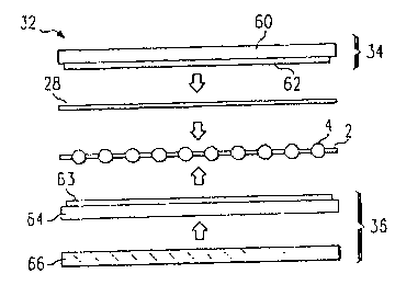
Referring first to Figure lla, the cell sandwich 32 includes upper pressure
pad
34, lower pressure pad 36 and the cell being manufactured which includes first
conductive sheet 2, solar members 4 and second conductive sheet 28. The cell
may
be a 300 cmz as shown in Figure 2c. As before, the pressure pads 34 and 36 act
as a
cushion so that the spheres 4 are not damaged during compression.
Figure llb illustrates a first of the many pressure pad configurations which
can
be utilized for the back bond process. The layers illustrated in Figure llb
are
summarized in Table 2.
CA 02195098 2004-O1-09
Table 2
Element Material Dimensions mm (inches)
Upper Pad Stainless steel152 x 365 x 0.05
34 60
(oxidized) (6.0 x 14.375 x 0.002)
Plaster 62 152 x 365 x 0.03
0.01
(6.0 x 14.375 x 0.001
0.0005)
Back Foil Aluminum 152 x 308 x 0.01
28
(6.00 x 12.125 x
0.0005)
Lower Pad Aluminum 64 152 x 365 x 0.05
36 (oxidized) (6.0 x 14.375 x 0.002)
Oxide on 0.0015
Aluminum 64 (0.000060") thick
Aluminum 66 152 x 365 x 0.20
(oxidized) (6.0 x 14.375 x 0.008)
Oxide on 0.0005
Aluminum 66 (0.000020") thick
Stainless Steel152 x 365 x 0.05
68
(oxidized) (6.0 x 14.375 x 0.002)
An alternate embodiment cell sandwich is illustrated in Figure 11 c. In this
embodiment, a plaster layer 63 (e.g., with dimensions of 152 mm (6.00") x 365
mm
(14.375") x 0.03 mm (0.001) ~ 0.01 mm (0.0005") is included on aluminum layer
64. In
addition, the stainless steel layer 68 can be eliminated (as shown) if the
oxide thickness on
aluminum layer 66 is increased to say 0.30 ~,m (0.000120").
Figure 11 d illustrates a cell sandwich 32 which is disposed between top
clamshell
plate 54t and bottom clamshell plate 54b. In this embodiment, the top
clamshell plate 54t
is coated with a ceramic release coating. This coating will directly abut back
foil 28. The
lower pressure pad 36 includes oxidized aluminum layer 64 and raw aluminum
layer 67.
As with the top plate, bottom clamshell plate 54b is coated with a ceramic-
like coating.
This embodiment does not require stainless steel sheets.
WO 96103775 ~ . ~ PCT1GB95101710
28
As discussed above with respect to Figure 1e, a plurality of apertures have
been
defined in the insulating layer 20. These apertures will expose: a portion of
the
sphere as also described above. The exposed portion of the sphere 4 is affixed
to the
second conductive sheet 28 by compressing the cell sandwich.
Prior to performing the compression step, the cell sandwich 32 may have light
pressure applied to ensure good thermal contact between the clamshell 54 and
the
foil sheets 2 and 28. This intermediate pressure step can be performed using a
vertical press and is usually included when using heated platens of a vertical
press
as the heating source. This step can perhaps be avoided if the furnace design
provides a good thermal environment for heating cell sandwich 3:: andAor
clamshell
54. When a clamshell 54 is heated using an infrared heating source, no
intermediate pressure step is needed. The weight of top plate ~i4t enhances
good
heat transfer.
The compression step to form the back bonds can be performed by use of a
vertical
press as described in the '319 patent (and as illustrated in ~i;ure 12a) or
more
preferably by a roll press as described above and as illustrated iin Figure
12b. A.s
with the front bond process, the combination of the pressure and i-,he heat
will cause
the conductive sheet 28 to bond to the spheres 4.
Tn the preferred embodiment, the electrical contact 26 and the second
conductive
sheet 28 are formed from the same sheet of material. In an alternate (less
preferred)
embodiment, this process can be performed in two steps.
In the first step, the electrical contact 26 is formed by comprEasing a
conductive
sheet (preferably aluminum) as discussed herein. That is, the conductive sheet
may
be compressed by using either a press ('319 patent) or a rolling device
(described
herein). The excess of the conductive sheet is then removed leaving a
conductive
pad 26 affixed to the core 12 of sphere 4.
CA 02195098 2004-O1-09
27
A second conductive sheet 28 (preferably aluminum) is then positioned over the
electrical contact 26. The aluminum sheet 28 and cell sandwich 32 are then
heated to a
temperature between about 400°C and 450°C (preferably about
420°C). The heated sheet
28 is then compressed against the array as described herein.
While this invention has been described with reference to illustrative
embodiments,
various modifications and combinations of the illustrative embodiments, as
well as other
embodiments of the invention fall within the scope of the appended claims.