Note: Descriptions are shown in the official language in which they were submitted.
W096/03540 2 1 q5 1 ~5 P~ v J5 -
APPARATTTQ FOR FEEDING FLATT~OR~ ~T~TrT.FQ
q'T''~ NICAT. FJT~T.n
The present invention relates generally to flatwork
article feeding r-~hin~c in commercial applications, and more
particularly, to an apparatus and method for transferring an
article of laundry from a loading station to a pickup station
where the article is ~n7~gQ~hl~ by a moving ~ niFm for
spreading and feeding the article into an ironer, folder or
other proc~Qsi ng equipment.
RA~R~R~T~TD ART
Typical spreader-feeder r--hin~c require an operator
to locate two corners of a sheet and insert them into clamps.
The clamps are then moved apart by one or more endless belts
or cables to spread the sheet in pL~alation for being
cul~v~y~d into an ironer or other pror~Qci ng equipment.
Attempts have been made to provide a spreader-feeder
machine which does not require an operator to locate and
manually clamp the corner portions of a sheet. For example,
U.S. Patent No. 4,031,639 to McCabe et al. discloses a
~L~ade~-feeder ~ nicm inrln~ing a plurality of spreader
belts which diverge to spread the sheet for rl~ L on the
feed Cullv~yuL. To load the sheet, an u~LatoI locates the
leading edge oP the 6heet and places a center portion on T he
spreader belts. One disadvantage of this type of machine is
the difficulty in keeping the leading edge of the sheet square
with the feed ~UII~yOL. If the operator does not properly
position the center portion of the sheet on the spreader
belts, the sheet tends to spread unevenly. An advantage of
the present invention is that it does not require as much
operator accuracy in positioning the sheet.
DISCLOST~ OF T~T~ lNv~ N
In accordance with the present invention, a transfer
' -n;~m is provided to grip a leading edge portion of a
flatwork article between leading corner portions thereof and
.. _ . _ _ . . . . . .
W096/03~40 ~ 9 5 ~ 9 ~ /v~ ~~
- 2 -
move the article from a loading station to a pickup station.
A positioning device is provided to locate a trailing edge
portion of the article at the pickup station for engagement
with a moving ~- ~n;~. In addition, a moving - -ni~m is
provided for engaging the trailing edge portion of the article
at the pickup 6tation and moving the article to a desired
location.
An advantage of this invention i5 that it does not
reqUirQ the operator to locate one or two corner portions of
the sheet and clamp the corner portion(s) to the moving
-n;~ or accurately place a leading edge on spreader
belts. Instead, an operator need only locate a leading edge
portion of the sheet for elly~g ~ with the transfer
~- -ni~ and the present invention automatically locates the
trailing corner portions of the sheet for pickup by the moving
- -ni~.
The present invention will be best understood by
reference to the following ~Pt~;led description taken in
conjunction with the ~ nying drawings.
BRIEF DESCRIPTION OF THE DRAWINGS
FIGURE 1 is a perspective view of the present
invention.
FIGURE 2 i8 a front view of the invention 6hown with
25 various ~: -n~ removed for clarity.
FIGURE 3 is a top view of the invention shown with
various c -~ts removed for clarity.
FIGURE 4 is a side view of the invention showing
various c ~nts in cro5s-section.
FIGURE 5 is a partial perspective view of the
inVention showing a transfer l~ ~nism, a moving -- ~ni~,
and upper and lower spreading 1 ~-h~ni -.
FIGURE 6 is an alternative ~o~ of the
invention showing a transfer apparatus, a moving ~~~h~ni.~,
and upper and lower spreading ~c ~ni
FIGURE 7 is a partial front view of the transfer
apparatus shown in Figure 6.
-
W096/03540 2 ~ q~ ~ ~5
~ - 3 -
FIGURE 8 is a partial side view of the transfer
apparatus shown in Figures 6 and 7.
FIGURE 9 is a partial perspective view of the
invention showing initial placement of a leading edge portion
of a sheet of laundry on a conveyor belt at a loading station.
FIGURE 10 is a partial perspective view of the
invention showing the sheet being transferred by the cunvuyo~
belt from the loading station to a pickup station.
FIGURE 11 is a partial perspective view of the
invention showing the sheet at the pickup station where a pair
of holding rollers are holding trailing corner portions of the
sheet and a pair of transfer clamps are engaging the trailing
corner portions.
FIGURE 12 is a partial perspective view of the
invention showing the transfer clamps retracted to a spreading
position where a pair of spreading clamps are engaging the
trailing corner portions of the sheet.
FIGURE 13 is a partial perspective view of the
invention showing the spreading clamps spreading the sheet for
sllhseq~nt placement on a feed COIIVUYUL.
DETATT~n ~ES~RTPTION OF T~ K~ ) ~MR~DTM~NTS
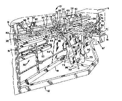
Referring to the drawings, Figures 1-4 show a
preferred ~o~ nt of a transfer, spreader, and feeder
appal~us indicated generally at 10. The apparatus 10
;nC~ c a frame structure 12 having vertical side walls 14
with a horizontal top ULUS5-r '--r 16, front cross-member 18,
and bottom cross-member 19 extending therebetween. A feed
ao.,veyuL 20 extends horizontally between the side walls 14 and
behind the front uLoss-r ' 18. The feed cullv~yur 20
;nr~ a plurality of spaced apart, flexible endless belts
22 which extend around a front roller 24 and a rear roller 26.
The front roller 24 is preferably driven through an endless
belt by a 1/2 HP (.374 KW) electric motor (not shown), and
the rear roller 26 is an idler roller. The belts 22 are
driven in a direction such that the upper runs of the belts 22
move rearwardly and the lower runs move forwardly. When a
W096/03540 P~~ ,5_~
~ 3
- 4 -
sheet i5 fed onto the feed conveyor 20, it is advanced
rearwardly to a flatwork ironer and automatic folder (not
shown~ .
To spread a sheet for placement onto the feed
Ou~ yUL 20, an upper spreader -?~hAn;~m 28 is located above
and in front of the feed CUII~ L 20. The spreader --~h~n;~
28 ;nCln~c an elongated endless member 30 extending
horizontally between the side walls 14 of frame 12. The
endless member 30 has front and rear legs 32 and 34 which are
parallel to each other in a horizontal plane and extend around
an idler pulley and a drive pulley (not shown). The pulleys
are rotatably mounted to the exterior of the side walls 14 and
the endless member 30 extends through cuL . ~ l; ng opPn; ngc
in the side walls 14. Preferably, the endless member 30 is in
the form of a toothed belt, although other types of belts or
chains can be used. The endless member 30 is driven through
the drive pulley by a 3-phase AC squirrel cage motor with an
inverter unit (not shown). An inverter unit of this type is
manufactured by ~itsubishi Corp. and sold as part number FRZ-
zo 024-0.7sx. Preferably, the motor is 1/3 HP (.249 Xw) and the
inverter is a 1 HP (.747 KW) unit. Alternatively, other means
can be used to drive the endless member 30, such as an air
motor, a DC motor, or a pneumatic cylinder.
To releasably grip and spread a sheet of laundry, a
pair of clamps 36 and 38 are mounted to the endless member 30.
In the illustrated ':'; t, the left clamp 36 is fixedly
attached to the front leg 32 and the right clamp 38 is fixedly
attached to the rear leg 34 of the endless member 30.
However, the clamps 36 and 38 can be coupled vice versa to the
front leg 32 and rear leg 34. Thus, the inverter motor is
adapted to move the endless member 30 in one direction to
spread the clamps 36 and 3s apart nnd in an opposite direction
to move the clamps toward each other. To guide the clamps 36
and 38 in a lateral direction, the clamps are movably
connected to a horizontal guide ~ar 40 which is connected to
the side walls 14 of frame 12.
The structure of the clamps 36 and 38 is
W096l03540 ~ 5 ~ ~ 5 r~ 09YE I
.
-- 5 --
substantially identical and will be described with like
numerals. The clamps 36 and 38 each include a front vertical
plate 42 and a rear vertical plate 43 having a pair of spaced
apart rollers 44 extending therebetween. The rollers 44 are
configured to roll along the guide bar 40 and support the
clamps 36 and 38. To provide additional guidance, a low
friction member 46 extends rearwardly from a top portion of
the front plate 42 for slidable contact with a front side of
the top ~LOSS ~ r. Similarly, a low friction member 47
extends forwardly from a top portion of the rear plate 43 for
slidable contact with a rear side of the top cross-member 16.
To grip OppOCi ng top corner portions of a sheet of laundry, a
pair of horizontal grippers 48 extend laterally inward from a
lower portion of each front plate 42 in a conventional manner.
Preferably, the grippers 48 are actuated by a double acting
pneumatic cylinder (not shown) to rapidly and securely clamp
the corner portions of the sheet between the grippers 48.
While the spreader r- '~n;Pm 28 including endless member 30
and clamps 36 and 38 are illustrated for purposes of
disclosure, it is contemplated that other spreading -- -ni Fmc
having different cu.,~LLuuLions may be utilized within the
scope of the invention.
Preferably, a lower spreader r - ' - n i _m 50 i8
provided to assist in spreading the sheet. The lower spreader
~ ni Fm 50 is positioned below the feed ~UIIV~yUL 20 and
in~lu~s two pairs of endless flexible belts 52 and 54 which
are driven by an inverter motor (not shown). The inverter
motor for the lower spreader r - ' -n; Fm 50 is preferably the
same type as the inverter motor for the upper spreader
-n; cm 28. The pairs of belts 52 and 54 extend laterally
outward from the centerline of the feed cu..v~yur 20 and are
positioned forwardly of the conveyor 20 to receive a sheet
therebetween. When the spreading clamps 36 and 38 begin to
move laterally apart, a lower portion of a sheet is placed
between the lower belts 52 and 54 as will be described in more
detail below. The sheet is then spread by the lower belts 52
and 54 at approximately the same rate as the spreading clamps
W096/03540 2 1 95 1 95 Ic~ 5~, ~4
- 6 -
36 and 38. Preferably, the inverter motor for the belts 52
and 54 is adapted to move the belts in the opposite direction
to return the sheet to the center position if a corner portion
of the sheet is released during the spreading operation.
To tr~nsfer a sheet of laundry from a pickup station
forwardly of the CUIlv~yoL 20 to a spreading station adjacent
the COIIV~Y~L~ a moving -5h~n; r~ 56 is provided. The moving
nir~ 56 ~nrl~ s a pneumatic cylinder 58 horizontally
mounted to the frame 12 in alignment with the centerline of
the feed conveyor 20. The cylinder 58 is positioned over the
feed conveyor 20 and above a plane defined by the spreading
clamp grippers 48. In addition, a horizontal bracket 60 is
attached to the end of a piston rod 62 which extends outwardly
from the cylinder 58. To releasably grip the corner portions
of a sheet, a pair of transfer clamps 64 are attached to end
portions of the bracket 60. The transfer clamps 64 each have
a pair of grippers 66 which extend horizontally forward from
the piston rod 62. Preferably, the grippers 66 are actuated
by a double acting pneumatic cylinder (not shown) to rapidly
and securely clamp the corner portions of the sheet between
the grippers 66. As will be discussed in more detail beloN,
the cylinder 58 is adapted to retract the transfer clamps 64
to a spreading position after the clamps have picked up the
corner portions of a sheet. In the spreading position, the
transfer clamp grippers 66 overlie the path of travel of the
spreading clamp grippers 48. Thus, the spreading clamp
grippers 48 move underneath the transfer clamp grippers 66 to
pick up respective corner portions of the sheet. The
spreading clamps 36 and 38 then move laterally apart to spread
the sheet. Alternatively, the path of the spreading clamp
grippers 48 can overlie the transfer clamp grippers 66 to pick
up corner portions of the sheet extending above the transfer
clamp grippers 66.
Other types of moving r ~h~n;r~c can be provided for
picking up the corner portions of the sheet and moving the
sheet in a desired manner. For example, a pair of spreading
clamps can be configured to transfer the sheet closer to the
W096/03540 ~îq5
_ - 7 -
uu,,v~yur as well as spread the sheet. In particular, the
spreading clamps can include rotatable grippers which pick up
the corner portions of the sheet at a pickup station, rotate
to transfer the sheet closer to the feed conveyor 20, and move
laterally apart to spread the sheet.
The transfer apparatus 67 includes a pair of spaced
apart delivery UOIIV~YUL belts 68 which extend parallel to the
- belts 22 of the feed conveyor 20. The delivery belts 68 are
endless, flexible members which wrap around a front roller 70
and a rear roller 72. The front roller 70 is positioned at a
forward loading station and the rear roller 72 positioned at a
pickup station closer to the feed CUIIV~YUL 20. The front and
rear rollers 70, 72 are interconnected by a horizontal support
member 71 which is mounted on a pair of vertical beams 73. To
provide a desired tension in the delivery belts 68, an
adjustable spring 75 acts against a shaft of the front roller
70. Preferably, the front roller 70 is idle and the rear
roller 72 is positively driven through a drive shaft 77 and an
endless V-belt 79 by a l/2 HP (.374 KN) electric motor (not
shown). The delivery belts 68 are driven in a direction such
that the upper runs thereof move rearwardly to transport a
sheet of laundry from the loading station to the pickup
station. To position the sheet ~or engagement with the
transfer clamps 64, the delivery belts 68 are centered with
respect to the feed Cu.,v~yuL 20 and positioned above the
horizontal plane of the transfer clamp gripper members 66. In
addition, the overall width of the delivery belts 68 is less
than the width of the sheet to allow side portions of the
sheet to drape over the outermost edges of the belts 68.
Preferably, the width of each delivery belt 68 is about three
inches (7 cm), and the overall width of the delivery belts 68
is 3-18 inches (7-46 cm). As will be ~i~CI~ccQd in more detail
below, the side portions of the sheet are subseguently
manipulated to locate the trailing corner portions for
engagement with the transfer clamps 64. As a result, an
operator can easily and guickly load a sheet by merely placing
a center portion of the sheet on the delivery belts 68.
W096/03540 .~~ . q
2 1 9S I 95
-- 8 --
To facilitate placement of the sheet on the delivery
belts 68, a curved spreader bar 81 extends forwardly beyond
the front roller 70 of the delivery belts 68. The spreader
bar 81 is preferably U-shaped to fan out the sheets 50 that a
center portion is directed onto the delivery belts 68 and the
side portions drape over the delivery belts 68 as the sheet
~L VyL ~sse5.
In order to grip the sheet and transfer it to the
pickup station, a pair of spaced apart gripper conveyor belts
74 are ~icposed directly above the delivery conveyor belts 68.
The gripper belts 74 are flexible, endless members which
extend around idle front and rear rollers 76 and 78. A
t~n-i~n;ng roller 83 is also positioned between the front and
rear rollers 76, 78 to produce a desired tension in the lower
run of the gripper belts 74. The rear roller 78 and
tensioning roller 83 are rotatably mounted on a pair of
~upport members 80 extending forwardly from the guide bar 40.
Preferably, the front and rear rollers 76, 78 of the gripper
belts 74 are positioned rearwardly of the coLL~ n~ing front
and rear rollers 70, 72 of the delivery belts 68. This allows
an operator to place a generous portion of the sheet on a
~ront portion of the delivery belts 68 to insure that the
sheet will not drop to the floor due to the weight of the
sheet.
To press the gripper belts 74 downwardly against the
delivery belts 68 in a free-floating manner, a pair of spring
biased pivot rods 85 interconnect the front and rear rollers
76 and 78. The rods 85 pivot about the shart of the rear
roller 78 which is rotatably attached to the support members
80. Thus, the gripper belts 74 cooperate with the delivery
belts 68 to grip a center portion of a sheet of laundry and
move the sheet by frictional engagement toward the feed
co,,v~yu~ 20. To prevent a sheet from being transported when a
previous sheet has not yet reached a desired location, a push
member (not shown) is provided. The push member acts against
the pivot rods 85 to force the gripper belts 74 out of
~ng-~ t with the delivery belts 68. When the gripper belts
W096l03~i40 2 1 95 1 ~
g
74 are pivoted upwardly, a sheet which is placed on the front
portion of the delivery belts 68 will not move because there
is not enough friction to carry the sheet.
To actuate the push member, a photosensor 89 is
disposed above the gripper belts 74 and rearwardly of the
front roller 76 (FIGS. 3 and 4~. Preferably, the photospncnrs
described herein are made by Microswitch and sold as P/N FE7B-
DB6-M. The photosDne~r 89 can be mounted on an upper portion
of the frame 12 extending over the desired location (not
shown). When a trailing edge of a previous sheet passes the
photosPncnr 89, a signal is sent to actuate the push member
which pivots the rods 85 and gripper belts 74 upward a short
distance and out of engagement with the delivery belts 68. As
noted above, this prevents a new sheet from being transported
before the previous sheet has reached a desired location.
When a material ready signal is received indicating that the
previous sheet has been grabbed by the gripper members 66 and
retracted to the spreading position, the push member is
retracted to allow the gripper belts 74 to freely float
against the delivery belts 68. The delivery belts 68 and
gripper belts 74 then cooperate to move the new sheet toward
the pickup station. In addition, the photosensor 89 prevents
jamming of the sheet if a new sheet is placed on top of a
previous sheet. In that event, the trailing edge of the
previous sheet will not be detected by the phot~cDneor 89, and
the first sheet will fall to the floor because there is
nothing to trigger the cl; _ing of the first sheet as
described below.
It is contemplated that other transfer - n;
having different constructions can be utilized within the
scope of the invention. For example, a single conveyor belt
and gripper belt can be utilized, and the belts can angle
upwardly from the loading station. Moreover, a movable clamp
can be provided to grip a central portion of the sheet from an
o~L~tOl. The movable clamp could be adapted to drape the
W096/03540 ~1951 ~5 r~ ClUS~E~
-- 10 --
sheet over a stationary guide member until the trailing corner
portions of the sheet are located for a moving ~ ~ni n~.
As the sheet advances on the delivery belts 68, the
draped side portions rise and pass over a pair of positioning
members 82. Preferably, the positioning members 82 are
configured as rollers ~;~pnsPd adjacent opposing ends of the
rear roller 72. The positioning rollers 82 are positively
driven by the drive shaft 77 and have respective clutch and
brake units 87 operably engaged thereto. The side portions of
the sheet are directed toward the positioning members 82 by a
pair of substantially vertical guide plates 84 which converge
inwardly toward t~rr;n~l ends of the positioning members 82.
In addition, a lower guide plate 86 is fl; npos~d underneath the
delivery belts 68 to direct the side portions of the sheet
toward the positioning members 82 (FIGS. 1 and 4).
Preferably, the lower guide plate 86 is made of a transparent
material. The lower guide plate 86 includes a central portion
88 which faces the Oll ing sheet. The central portion 88
angles upwardly and rearwardly from the floor toward a center
section of the front crons '--r 18 which ~U,UyuL Ls the rear
roller 72. The lower guide plate 86 also includes lateral
portions 9o which angle forwardly and outwardly from the
central portion 88 to catch and direct the side portions of
the sheet.
Other positioning members can be used to locate the
trailing corner portions of the sheet. For example, the
positioning members can be configured as end portions of the
rear roller 72 which extend beyond the outermost edges of the
delivery belts 68. The positioning members could also be
configured as ~ixed cylinders or curved plates to allow the
side portions of the sheet to pass thereover. IloIeuv~L, other
guide members can be provided to direct the side portions of
the sheet toward the positioning members. For example, the
positioning members could have end plates extending radially
outward therefrom.
As the side portions of the sheet pass over the
positioning members 82, they are held down by a pair of idle
W096l03540 2 1 ~ 5 1 9 S I~~
-- 11 --
nip rollers 92. The nip rollers 92 are rotatably attached to
the support members 80 and are passively driven by the
- positioning members 82. Preferably, the support members 80
are relatively thin to allow deflection which -~tes for
the variable th i rknPss of the sheet as it passes between the
nip rollers 92 and the positioning members 82. As the sheet
progresses, the leading edge falls toward the floor until the
entire sheet ~;~Png~gPs the delivery belts 68 and only the
trailing corner portions remain between the nip rollers 92 and
the positioning members 82. It will be appreciated that a
central portion of the trailing edge advances at a faster rate
than the trailing corner portions of the sheet because the
central portion is carried directly by the delivery belts 68.
Preferably, a support plate 94 is ~icpo~Pd underneath the rear
roller 72 to support the sheet as it falls from the delivery
belts 68 (FIGS. 1 and 4). As with the guide plate 86, the
support plate 94 is preferably made of a LL~IID~a~nL material
to allow an operator to view the procPssing of the sheet.
Once the sheet has reached the pickup position and
the trailing corner portions are located between the nip
rollers 92 and the positioning members 82, the clutch and
brake unit 87 ~i~PngageS the positioning members 82 from the
drive shaft 77 and stops rotation of the positioning members
82. At the same time, a pair of retractable shoes 98 are
forced against respective ones of the nip rollers 92 by a
pneumatic cylinder 100 (FIG. 4) to prevent rotation o~ the nip
rollers 92. Thus, the trailing corner portions of the sheet
are held in position between the positioning members 82 and
nip rollers 92 for pickup by the transfer clamps 64.
Preferably, the nip rollers 92 and the shoes 98 are rotatably
attached to the pivotal support members 80 so that the nip
rollers 92 are in free-floating ~ny~y. -nt with the
positioning members 82. To facilitate gripping of the
trailing corner portions of the sheet, the positioning members
82 are preferably wrapped with a high-friction material such
as polyurethane.
Other types of holding devices can be provided for
W096/03s40 ~1 9 ~ 1 9 5 pCT~S9~09984
- 12 -
holding the tr~; l;nq corner portions of the sheet in the
desired location. For example, the nip rollers 92 can be
positively driven at the same speed as the positioning members
82. A second clutch and brake unit can also be provided to
~icPnqaqe the nip rollers 92 from their respective drive
shafts and stop rotation thereof. I~JL~UV~r~ the transfer
a~al~Lu~ 67 as a whole can be mounted on a separate frame to
allow retrofitting to existinq spreader-feeder r-~h;nP&
An alternative Pmho~i- L of the transfer apparatus
67 is illustrated in Figure 6. Since the ~ -nt in Figure
6 has portions similar to the previously described Pmho~;r-nt~
8imilar parts are represented by the same, coLL~ ;nq
reference numerals. The transfer apparatus 67 includes a
single delivery COIIV~YUL belt 102 which extends in the same
general direction as the belts 22 of the feed conveyor 20.
The delivery belt 102 is an endless, flexible member which
wraps around a front roller 104 at the loading station and a
rear roller 106 at the pickup station. The front roller 104
is positioned below the rear roller 106 50 that the delivery
belt 102 angles upwardly from the loading station to the
pickup station. Preferably, the front roller 104 is idle and
the rear roller 106 is mounted on a drive shaft 108 which is
positively driven through an endless V-belt lO9 by a 1/2 ~P
(.374 XW) electric motor 110 with an inverter unit.
To position the sheet for Pnqa~, L with the
transfer clamps 64, the delivery belt 102 is centered wlth
respect to the feed CUIIV~UL 20, and the rear roller 106 is
positioned above the path of travel of the transfer clamp
gripper members 66. In addition, the width of the delivery
belt 102 is preferably about three inches (7 cm) wide, which
is less than the width of typical laundry articles processed
by spreader-feeder r-~h in~c Thus, the relatively narrow
width of the delivery belt 102 allows side portions of the
sheet to drape over the delivery belt 102 for subsequently
locating the trailing corner portions of the sheet. A curved
spreader bar 107 is also provided to fan out the sheets when
initially placed on the delivery belt 102. Preferably, the
W096l03540 ~q 5 ~ ~5
- 13 -
spreader bar 107 is about seven inches (18 cm) wide and about
36-42 inches (91-107 cm) high. In addition, a telescoping
support leg 111 interconnects the delivery belt 102 and the
frame 12 to allow adjustment of the height and angle of the
delivery belt.
To grip the sheet and transfer it toward the feed
CUI~VUYUL 20, a gripper ~ol.V~yuL belt 113 overlies the delivery
co..v~yu~ belt 102. The gripper belt 113 is a flexible,
endless member which extends around a front roller 112 and a
rear roller 114. The front roller 112 is positioned below the
rear roller 114 so that the gripper belt 113 angles upwardly
at the same angle as the delivery belt 102. Preferably, the
front and rear rollers 112, 114 of the gripper belt 113 are
offset from the cuLL~ nn~;ng front and rear rollers 104, 106
of the delivery belt 102. The front roller 112 is idle and
the rear roller 114 is mounted on a transverse shaft 116 which
is rotatably connect~d to a pair of pivot arms 118. The pivot
arms 118 are pivotally rnnnected to a pair of support plates
120 which extend upwardly from the front cross~ r 18 of
the frame 12. In addition, the shaft 116 is positively driven
in the opposite direction of the shaft 108 through the V-belt
109. Thus, the gripper belt 113 is driven at the same speed
as the delivery belt 102 and cooperates therewith to grip a
center portion of a sheet of laundry and move the sheet toward
the feed cGIlv~yor 20. In addition, the V-belt 109 and pivot
arms 118 act to hold the gripper belt 113 downwardly against
the delivery belt 102. The combination of a relatively low
front roller 104 at the loading station, the angle of the
delivery belt 102, the offset orientation of the gripper belt
113 relative to the delivery belt 102, and the spreader bar
107 facilitates the ease and speed with which an operator can
load a sheet of laundry onto the delivery belt 102.
As the sheet advances on the delivery belt 102, the
draped side portions rise and pass over a pair of positioning
rollers 122. The positioning rollers 122 are attached to the
drive shaft 108 adjacent the ends of rear roller 106 of the
delivery belt 102. In addition, each positioning roller 122
W096~3s40 2 ~ 9 ~ t 95 r~ 3~
- 14 -
has an associated clutch and brake unit 124 operably attached
thereto. As the side portions of the sheet pass over the
positioning rollers 122, they are held down by a pair of idle
nip rollers 126. The nip rollers 126 are mounted on a
transverse rod 128 and are actively driven through the V-belt
109 by the motor 110. The rod 128 is rotatably attached to a
pair of arms 130 which are pivotally attached to the support
plates 120. To force the nip rollers 126 against the
respective positioning rollers 122, a spring 132 is attached
to pivot arm 130 and the front ~,oss- hPr 18. In addition,
each nip roller 126 has an associated clutch and brake unit
134 operably attached thereto. When the trailing corner
portions of the sheet are between the positioning rollers 122
and the nip rollers 126, the clutch and brake units 124 and
134 ~;CPngage and stop rotation of their respective rollers
122 and 126. The trailing corner portions of the sheet are
therefore held between the positioning rollers 122 and the nip
rollers 126 until the transfer clamps 64 pickup the corner
portions.
It is contemplated that multiple transfer ~- ~ni,
67 can be used to feed sheets to a plurality of cuLL~ ; ng
spreading stations. For example, a pair of transfer
r- ~ i, 67 could be used to transfer sheets of laundry to a
pair of moving me-h~ 56 and two sets of curL~ inq
8preading clamps 36 and 38.
Figures 9-13 illustrate the operation of the present
invention. Figure 9 shows a sheet S placed on the delivery
belts 68 such that side portions 138 of the sheet drape over
the outermost edges 140 of the delivery belts 68. The
delivery belts 68 and the gripper belts 74 cou~el~te to grip
the sheet S and carry it rearwardly toward the feed ~UIIV yUL
20.
As the sheet s ~oyLesses further, the side portions
138 rise and pass between the positioning members 82 and the
nip rollers 92 as shown in Figure 1o.
As shown in Figure 11, the leading edge 136 falls
toward the floor until the entire sheet s disengages the
W096/03540 2 ~ 5 r~l,u~ J5. ~
- 15 -
delivery belts 68 and only the trailing corner portions remain
between the positioning members 82 and the nip rollers 92. To
detect when the sheet S is properly positioned for pickup by
the transfer clamps 64, a pair of photocPncors 146 (FIGS. 2
5 And 4) are ~iCp~CPd adjacent a lower front portion of the
positioning members 82 (see FIG. 4). When the trailing corner
portions leave el-y~ with the respective photosensors
146, signals are sent to actuate the associated clutch and
brake units 87. The clutch and brake units 87 then disengage
their respective positioning members 82 from the drive shaft
77 to stop rotation of the positioning members 82. At the
same time, the respective pneumatic cylinders 100 are actuated
to force the shoes 98 against the nip rollers 92 to stop
rotation of the nip rollers 92 and thereby clamp the trailing
corner portions 138 of the sheet S against the nip rollers 92
in position for pickup by the transfer clamps 64. The clutch
and brake units 87 and the cylinders 100 are in~pppn~ntly
actuated to clamp the corner portions. Thus, if the sheet S
is laid crookedly on the delivery belts 68 or completely off-
center, one corner portion can be clamped and held at the
pickup station until the other corner portion catches up and
is subsequently clamped.
When both trailing corner portions of the sheet S
~lcPnqage the photos~ L ~ 146 and are properly held at the
pickup station, a signal is sent to actuate the pneumatic
cylinder 58. The transfer clamps 64 are moved forwardly from
the retracted spreading position to the pickup station. The
grippers 66 are closed to clamp the corner portions. At the
same time, the spreading --- ~.n;cm 28 is actuated to begin
moving the spreading clamps 36 and 38 toward each other.
As shown in Figure 12, the transfer clamps 64 are
then retracted to the spreading position for pickup by the
spreading clamps 36 and 38. The spreading clamps 36 and 38
reach the spreading position shortly after the transfer clamps
64, where the spreading clamp grippers 48 receive the corner
portions of the sheet S underneath the transfer clamp grippers
66. Preferably, proximity sensors (not shown) are positioned
wo96lo3s4o ~lq ~ .5
- 16 -
to detect when the respective spreading clamps 36 and 38 reach
the spreading position in Figure 12. The proximity sensors
are preferably made by Electromatic and sold as P/N ACFlONPO.
When the spreading clamps 36 and 38 reach the proximity
sensors, the spreading clamp grippers 48 are closed to clamp
the corner portions of the sheet S. The transfer grippers 48
are then opened to release the sheet 5, and the clamps 36 and
38 are moved apart to spread the sheet S as shown in Figure
13. When the sheet S is spread by the clamps 36 and 38, a
lower portion of the sheet is gripped by the lower spreader
belts 52 and 54 to assist the spreading operation. Figure 13
also shows a second sheet S2 being placed on the delivery
belts 68.
The operation of the ~ ~o~; ~ shown in Figures 6-9
is essentially the same as the above described ~mho~ nt.
Rather than using the passively rotatable hold-down roller 92
and the pneumatically actuated shoe 98, the clutch and brake
units 134 are ;nderrn~rntly actuated to stop rotation of the
respective nip rollers 126. In addition, the clutch and brake
units 124 are ;nderrn~ntly actuated to stop rotation of the
respective positioning rollers 122. Thus, when the trailing
corner portions 136 of the sheet S ~ ngage the photosensors
146, a signal is sent to the clutch and brake units 126 and
134 to d;~ngage their respective drive shafts 108 and 128.
The rotation of rollers 122 and 126 is then halted to thereby
clamp the trailing corner portions 138 of the sheet
th~ cn.
Although the present invention has been described
with reference to preferred ~mho~;r ~s, those skilled in the
art will rerogn;ze that changes may be made in form and detail
without departing from the spirit and scope of the invention.
As such, it is intended that the foregoing detailed
description be regarded as illustrative rather than limiting
and that it is the appended claLms, ;nrln~;nrJ all equivalents
thereof, which are intended to define the scope of the
invention.