Language selection

Search

Patent 2195212 Summary

Third-party information liability

Some of the information on this Web page has been provided by external sources. The Government of Canada is not responsible for the accuracy, reliability or currency of the information supplied by external sources. Users wishing to rely upon this information should consult directly with the source of the information. Content provided by external sources is not subject to official languages, privacy and accessibility requirements.

Claims and Abstract availability

Any discrepancies in the text and image of the Claims and Abstract are due to differing posting times. Text of the Claims and Abstract are posted:

  • At the time the application is open to public inspection;
  • At the time of issue of the patent (grant).
(12) Patent Application: (11) CA 2195212
(54) English Title: LIFE-SAVING DEVICE WITH LAUNCHER
(54) French Title: DISPOSITIF DE SAUVETAGE AVEC LANCEUR
Status: Deemed Abandoned and Beyond the Period of Reinstatement - Pending Response to Notice of Disregarded Communication
Bibliographic Data
(51) International Patent Classification (IPC):
  • B63C 9/22 (2006.01)
  • B63C 9/18 (2006.01)
  • B63C 9/26 (2006.01)
  • F42B 12/68 (2006.01)
(72) Inventors :
  • BAUTISTA REAL, JOSEP ANTONI (Spain)
  • SORIANO COLOMINA, ROSA MARIA (Spain)
(73) Owners :
  • JOSEP ANTONI BAUTISTA REAL
  • ROSA MARIA SORIANO COLOMINA
(71) Applicants :
  • JOSEP ANTONI BAUTISTA REAL (Spain)
  • ROSA MARIA SORIANO COLOMINA (Spain)
(74) Agent: SMART & BIGGAR LP
(74) Associate agent:
(45) Issued:
(86) PCT Filing Date: 1996-03-01
(87) Open to Public Inspection: 1996-11-21
Availability of licence: N/A
Dedicated to the Public: N/A
(25) Language of filing: English

Patent Cooperation Treaty (PCT): Yes
(86) PCT Filing Number: PCT/ES1996/000043
(87) International Publication Number: WO 1996036530
(85) National Entry: 1997-01-15

(30) Application Priority Data:
Application No. Country/Territory Date
P 9500996 (Spain) 1995-05-17

Abstracts

English Abstract


The object of the invention is a life-saving device with launcher which
provides for the automatic inflation of the float by simply acting on a lever.
The mechanism is comprised of a gas tank or similar integral at its top
portion with the float so that said tank is traversed by a hollow cut-off cock
whose lower end projects from the container or tank and is terminated by the
lever, the upper end being introduced inside the float and the gas penetrating
through the hollow tube of said cock. Integral with the assembly is provided a
ring which is connected to the rolled-up cable which is itself integral with
the launcher, the latter being provided with a gun wherein is introduced the
life-saving assembly in order to launch it to a major distance.


French Abstract

L'objet de l'invention est un dispositif de sauvetage avec lanceur qui permet le gonflage automatique du flotteur par le simple actionnement d'une manette. Le mécanisme comprend un conteneur ou réservoir de gaz ou autre solidaire à sa partie supérieure du flotteur, de sorte que ce conteneur est traversé par un robinet de fermeture creux, dont l'extrémité inférieure dépasse du conteneur et se termine par la manette, l'extrémité supérieure étant introduite dans le flotteur, le gaz pénétrant à travers le tube creux du robinet. Un anneau solidaire de l'ensemble est relié à un câble enroulé lequel est à son tour solidaire du lanceur dans le canon duquel est introduit l'ensemble de sauvetage dans le but d'être lancé à une plus grande distance.

Claims

Note: Claims are shown in the official language in which they were submitted.

- 8 -
Claims
1. A LIFE-SAVING DEVICE WITH LAUNCHER, essentially
characterised by consisting of a float integral with a
box or container, which box is traversed crosswise by a
cut-off cock, the bottom of which is integral with a
lever that is turned and then pressed to activate the
start of the float inflating process, upon the release of
the gas contained in the container. Said box or container
moreover has an outer rubber or similar cover housing a
small ring integral with a steel wire cable, the latter
being in turn integral with the rest of the assembly or
housing. Furthermore, the top of the box or container has
integral rods with a metallic connecting or cover plate
right above the line of the cut-off cock, said plate
serving as a stop for the cut-off cock when the later
moves up.
2. A LIFE-SAVING DEVICE WITH LAUNCHER, as in claim 1,
essentially characterised in that the top end of the tube
which conforms the cut-off cock has holes that allow the
passage of gas towards the float because when the outer
lever is pressed, the lever acts on the cut-off cock to
push it up until it abuts against the metallic plate,
thereby for the cut-off cock holes to reach into the
float and for the gas contained within the box to expand
into the float through said holes.
3. A LIFE-SAVING DEVICE WITH LAUNCHER, as in claims 1
and 2, essentially characterised in that the life-saving
float is integral with and sealed to the top end of the
box or container whereas the top end of said float is
also integral with a half-oval concave rubber that in
turn wraps the entire folded float, as a hood or bathing
cap. Said float is further provided with nylon or any

- 9 -
other strong light material ribbons, two of which extend
downwardly across the hood from side to side, connected
at the top and ending in rubber balls or tassels that are
in turn inserted in cavities of the same material,
whereas a third transverse ribbon, also integral at one
end, surrounds the hood halfway up the same and is fitted
as a nail or rubber stop within a small hole in the hood.
4. A LIFE-SAVING DEVICE WITH LAUNCHER, as in claims 1,
2 and 3, essentially characterised in that the ring that
is integral with the float referred to in claim 1 is
directly connected to the launcher roll-up cable, and
thus the entire life-saving device assembly -float and
box- is inserted within the launcher gun, bringing the
cable into register with the longitudinal groove located
along the gun, and is then dropped inside the same until
it abuts against the stops at the bottom inner end of the
launcher gun, whereupon the ejecting mechanism acts on a
cylinder ending in a cone shape with concave sides, and
which has a flat base and a diameter that is slightly
greater than that of the box lever, the cylinder exerting
the required pressure on the lever to cause the float
inflating process to begin.
5. A LIFE-SAVING DEVICE WITH LAUNCHER, as in claims 1,
2, 3 and 4, essentially characterised in that the
launcher cable claimed hereinbefore is integral with a
cable stand, and thus in order to make a rescue once the
casualty is physically in contact with the float, the
lever with which the cable roll stand is fitted need only
be acted on.

Description

Note: Descriptions are shown in the official language in which they were submitted.


~;LE, r!~3 ~ Th;~i A~i ~ 521 2
T~ -RA!~LA~lON'i
,
LIFE-SAVING DEVICE WITHi LAUhCi-iER
DescriPtlor,
Tne patent of lnvention proposed in ti-lis specification
relhtes to a LIFE-SAVI~iG DEVICE WITH LAUNCHEF; whlch
substant1ally improvves the state of the art over what was
kr,own aiid used heretofore.
O arlefly speaking, thls patent of inventlor, concentrates
on an automatically inflatable pliable l1fe-savlng device
complete with a second devlce enabling the lifebelt as
such to be launcr,ed over a substar,t1al distance.
There are substantlal hazards involved in ti-,e practisir,g
of water sports, ascribable to either the recklessr,ess of
whose who practise such sports, poor weather conditior,s,
the state of the sea or any otr,er contingency whlch may
result in an accider,t. If an accident sl-,ould ensue,
clearly placing the casualty's life at stake, prompt
action is vital and requires having means of guaranteed
or assured effectiveness. Tear,s of specialised lifeguards
are now regularly available at beacr,es and similar areas,
but tr,e means they r,avee are still lir,ited and sometimes
ineffective. For instance, lifebelts cannot be used in
heavy seas and witi-, a strong head wir,d, for they cannot
be placed within reach of the casualty.
Tl-lis pateut of inver,tion proposes solvins such problems
specifically by means of an automatically lnflatable,
reusable, rechargeable, compact small pliable lifebelt.
This lifebelt consists of two m,ain dlstir,ct parts wi-,ici-,
altogetr,er r,ake up a global 11fe-saving syster,: the life-

~ O ~,~ O C i C~ Cl
t t Pl a' ~ ~ p~ n -r c) o, rl 3 pi n ~t a~ t n)t ~r u) $
a m n Om m m ~ m rl - ' ::) o ~t CL O -' rn p 3 -~ ~
~r v ct ~L _~ t~ a~ c) ri D)_r n)r pi pl ri a~ a~ p~ -i n~ O C~
al Or i -i a~ ~ ~ O t~ ~ rL a~r n~ ~ J - ~t ~t U) -~ U Ct O ~t
D~ _ nl _r ~i ~ < ~pi p) a' o ~h ~~ ~t CL a p c) ~ p~ X i o ~ U)
-b i r ~a tD P~ ~ ~~ c ~ rL - -~ -r ~- -- 3 o ~t 3 h ) a n, - n
n tp) rL p) c ~ ~ -- -r p~ ~ i t 0 -' ~ ~Jl -i' U~ - U) ~ Ui _ -P~ o, -i
i~ 3 h -h i~ u ~ ai h < a) cr -i L ~t ~ a~ ~ t irh -- -) ~ P~ P ~r
~ o tD _~ ~i ~ -r o o O -h - it -- . ~h o a) -~ t -r - u~ ~ <~
a x ~t ~ 3 ri) a ~ ~ L rr a p) , a~ u) ~r o ~ p~ o u) t
O ~' O ~t ~ - - rD P~ ~ -C ~ c) p~ ~t ~- p, --_,, U Ct a) P
~ ~ U) u) a) a)r ~ P -~ _ o -r ~ ui ~,t QD U~ J CL _,, _~ i, -h u) ~o
rj p n rn -- _I tc~ <, a o ~- al al~u~ c~ c -h ~t c-oi ~ Jh J ~' - p~ - t~i
~r t- o -i cr n~- O r- U un ~t -r oi ar -i trt -r U cr ci
P~ tt p) ~i ~t ot q O -- tD ~ t~ t a,r ot a~r ,C ' -r ~D -i tcDr

~il C~ l O C~ C) C~
a~ g c -) ~ 3~ P) C ~ -r ~ r -r ~ O ~ o ~ p~ g ~l o o ~ Cl - Or r~ -h P~
a u~ r~ ~ ~ ~ ' ~ ~i < ~ - n~ - U) ~ ~ a) Cr p~ ~a, P~ a) a) Cr a -~ u~ v~ ~nr c a~ nU~
U) - ~ P -- -~ C) 3 ~ n) ~ n ~ -l S -l ~- -) p~ a~ p) p)
p) a - a p~ n '~ p) - o a~ p) ~ u~ ~ 3~ 0- n~ ~ a ~ u) p)
r a~ pJ a ~) c p~ ~ o ~ ~ p~ u) p~ a Ch 3 a c~ a -h
, ~ ~ n~ ~ a ,~ ~
n) ~ Q~ CL ~ . ~ _ <~ --hh ~ cr ~ P) ~ --r o~ --- p~
~ n ~ ~ a~ ~ -r O n ~ ~C~ ~ ~ o r ~ ¦ r- ~ c ~ O
r -h O --' C~ (D p~ - ~ C ~ C C ~ o -h n~ O _r P~ r
o ~ ~ r~ ~ c O ~r ; O ~ ~ U ~ S _, I
O ~ _,. p~ p~ C ,~ X ~ S ~ ~r p -~ o ~ r ~r S P~ n ~ p, a3) ~ r~ c s
O n ~ ~~ ~ P~ ~ ~ a' u' P' X uP) r- a, ~ a, ~ P~ u; a) ~ a, r~ ~ S O P) -r ~ u C~ ~

21 9521 2
slde/ w7thlr a small recess formed by the same rubber
(17), a smlall rir,g is housed intesral wlth a plasticised
steel Wl î e cable (1~3) of little thlchr,ess, the latter
being in turn 1r,tesral with the rest of the assem,bly or
housing. A m,ar,ual pressure lndicator (19) ~s hGused on
the other side of the devlce, serving to ir,form, of the
existing pressure, to wh1ch end it need only be pressed
with a finger and checl~ed to see whether it retrieves its
initial positlon.
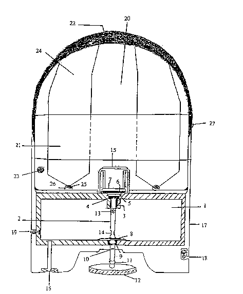
The same FI&URE 1 shows detai 16 of part of tl-lê float,
which corsists of a llfe-saving float (20) with an outer
section ln ti,e form of a small secant lir,e (if ar,d when
inflated) with the same sl~e as the top of the metallic
1 J box (1), and thus this end of the float (20) and the top
of the box (1) are fully and sealinglj ir,tegral with each
other. The float is folded at this area of the device in
the form of bellows or an accordion (not as a sheet). Tihe
other diametric end of the float t2C) is integral with a
2C concave hâlf-oval rubber (22) whicl, would in turn wrap
the entire folded float, as a hood or bathir,g cap. A
(conventional) one-way emergency blower (23) is also
included. Three nylon or ar,y other stror,g light m,ateriâl
ribbor,s are finâlly provided: two are downwardly directed
2~ across the hood from side to side, are conr,ected at the
top 124) ar,d end ln rubber balls or tassels (2~) that are
ir, turn inserted ir, cavities of the same material (2~),
and a third transverse ribbon (21), alsG lntegral at or,e
erd, is arranged halfway up the hood, thereb~ to surrour,d
3C tl-le same and be fitted as a nail or r-ubber stop witi-lirl a
small hole (27) in the hood. These three ribbor,s complete
tne plcture of this part of the item, ard the assembly
ti-,us obtair,ed is aerodyr,amic and compact.

2l 9521 2
The operatlon of thls devlce lS very slmpla, as detalled
lr, FIGL'RE 2. The lever ~12) of the cut-off cock (2j r,eed
or,lj be turned to release the cock from the thread er,d
(~). Then, a sll3ht pressure or, such lever (12) causes
the whole of the hollow tube assem,bly lns7de tha box to
move up until it abuts against the ,metalllc plate stop
(1~). This wtll moreover prevent a casualty, panlc-
strlcker, as is ti~,e rule 1n these cases, frGr,causing the
mechanism to retr1eve lts prev1Ous position by hlttlng or
llugsin3 lt in desperation. Tl,a rebate operîillgs (14)
remair, within the reGeptacla, whereas the small pores on
the top (13) cor,r,unicate with tt-,e outslde of the box or
container ~1), i.a. with the inslde of the lifebelt (20).
The dlfference lr, pressure and the r,eed of the gas or
1~ compressed alr to expand creates a passage for tha gas to
flow from, its tank ir, the box (1) lnto the float (20),
wi-,lch shall l,ave beer, folded ur,tll tl-,er,. The gas acts to
gradually lnflate the float, pushing the nyion ribbons or
strlps wl-,lch are released from ti,elr faster,lr,gs (2~) and
2G (27~. The hood (22) will graduall~ rlse and draw
dlametrlcally away fror,tlhe box, tl-,ese two elemer,ts, Vl~.
tl,e box and the hood, flnally becomlng the er,ds of the
lnflated float, as shown ln detall in FIGURE 3.
~i-len the dlstar,ce at whlcll the casualty lles ls very
large, and m,ailual launching cannot be resorted to, tl-,ls
Llfe-Savlng Devlce ls fitted wlth ar,element that allows
lt to be laur,ci-,ed, automatlcalli ir,flatlr,g tl-,e float.
FIGU'RE 2 shows ln detall the posltlon of the safety rlr,g
3G (18), housed wlthln a recess ir, tl,e rubber ar,d connected
to a cable that is lr, turr,integral witll the rest of the
device. ~s showrl lr, detall in FIGURE 4, said ring l5
cor,nectad to the roll-up cable (23) of the launcher. The
lever (12) tl~lerl turns to be released frcm the trlread (i~)
3~ wlthout thei~e belr,g ar,y risk of leakage beca~se of tl-le
_ . . ~ . _ ..... .. . .

~lO c~ o ~ c~ t
P~p~ ~ ~ p, a P~ a ci ~ c P a, a ~~ a~ r a) a a) a, a n
~ ~ a~ a, ~; P~, P a r, a~ ~ ~i c, ~ ~ a~ ~ ~ A a r p a r a ~ r r ~ ~- 3
~ n ~ O ~ ¢ a~ a ~
ot - ¢~ p aj ~ - rt - r a~ ~t p) -l -) ¢ ~ c ~t ( 3 -- ~ ¢ cl a) l ~ a
r- o ~ ~ r ~ n ~ f ~ r- ~
i L - iPL p~ ir o ~ ala, ~ ~~ ~r ~n c~ -c a Pt ~. ~ P~ ~r ~ ¢ c r~. p, . -r
L~ r~ O ~ r
n - C ~, a~ ~ a - t 3 j ~ i n~ ar c~ p) P~ ) a r a _
Cl a '~~ ~ ~' t cr ~ ..... u) -r o ~ c~ 0~ u) -h ¢r n s P~ U ) a p v ai cr ~- ~r r
~~ c o ~ ~i cr ai 'tr ; r- .. o .. P~ -r pi .. ~t ~t h ~) a i~ -~ < i" - p, ~t c
t ~) a o ~ o ~ a Q i ~ 7; -; o ~t ~ -r o p~ c _ a~r ~ ~ ~u cL ¢~r _ o

21 9521 2
cabla for an easler locatlûn thereof in poor v,sibility
corditlor,s. Due to ,he design, the a1r or gas cor,talned
ir, the tank is highly protected and there are therefore
absolutely no chances of leakage due to the safety of the
seals. Tnere is very little mair,ter,ar,ce whicr, cor,slsts
merely of regular safety checks. Its small size r,oreover
allows lt to be easily carried and stored.
The patent of inventior hereir, proposed car, witl-,ln lts
essence, be otherwise emlbodied in practice, wit" varyir,g
materials and sizes, whicil shall also be covered by the
protect10n applied for'-,ereir and which will at no event
alter the spirit of the claim,s.

Representative Drawing
A single figure which represents the drawing illustrating the invention.
Administrative Status

2024-08-01:As part of the Next Generation Patents (NGP) transition, the Canadian Patents Database (CPD) now contains a more detailed Event History, which replicates the Event Log of our new back-office solution.

Please note that "Inactive:" events refers to events no longer in use in our new back-office solution.

For a clearer understanding of the status of the application/patent presented on this page, the site Disclaimer , as well as the definitions for Patent , Event History , Maintenance Fee  and Payment History  should be consulted.

Event History

Description Date
Time Limit for Reversal Expired 2001-03-01
Application Not Reinstated by Deadline 2001-03-01
Deemed Abandoned - Failure to Respond to Maintenance Fee Notice 2000-03-01
Application Published (Open to Public Inspection) 1996-11-21

Abandonment History

Abandonment Date Reason Reinstatement Date
2000-03-01

Maintenance Fee

The last payment was received on 1999-02-17

Note : If the full payment has not been received on or before the date indicated, a further fee may be required which may be one of the following

  • the reinstatement fee;
  • the late payment fee; or
  • additional fee to reverse deemed expiry.

Please refer to the CIPO Patent Fees web page to see all current fee amounts.

Fee History

Fee Type Anniversary Year Due Date Paid Date
MF (application, 2nd anniv.) - small 02 1998-03-02 1998-03-02
MF (application, 3rd anniv.) - small 03 1999-03-01 1999-02-17
Owners on Record

Note: Records showing the ownership history in alphabetical order.

Current Owners on Record
JOSEP ANTONI BAUTISTA REAL
ROSA MARIA SORIANO COLOMINA
Past Owners on Record
None
Past Owners that do not appear in the "Owners on Record" listing will appear in other documentation within the application.
Documents

To view selected files, please enter reCAPTCHA code :


To view images, click a link in the Document Description column. To download the documents, select one or more checkboxes in the first column and then click the "Download Selected in PDF format (Zip Archive)" or the "Download Selected as Single PDF" button.

List of published and non-published patent-specific documents on the CPD .

If you have any difficulty accessing content, you can call the Client Service Centre at 1-866-997-1936 or send them an e-mail at CIPO Client Service Centre.


Document
Description 
Date
(yyyy-mm-dd) 
Number of pages   Size of Image (KB) 
Representative drawing 1997-10-14 1 18
Cover Page 1998-06-15 1 16
Description 1996-11-21 7 272
Cover Page 1997-05-01 1 16
Claims 1996-11-21 2 80
Abstract 1996-11-21 1 20
Drawings 1996-11-21 3 64
Reminder of maintenance fee due 1997-11-04 1 111
Courtesy - Abandonment Letter (Maintenance Fee) 2000-03-29 1 183
Fees 1998-03-02 1 37
International preliminary examination report 1997-01-15 18 481