Note: Descriptions are shown in the official language in which they were submitted.
~ WO 96/04475 ? 1 9 5 6 5 4 ~ U~
.. .. .
HIGH PRESSURE Dl[ESEL FUEL PUMPS
USING A TVVO-PIECE PIJMP PL11NGER
T~rhni~ Field
- This inventio~ is directed to fuel pumps,
partirnlArty electronic unit fuel pumps and ;ntegr~ted
or separate unit injectors for delivering diesel fuel at
ultra-high pressures to heavy duty diesel engines.
~q ~ ~ Art
ConvPn~;nn~lly, for many years, unit fuel
injectors for heavy duty diesel engines, such as used
for e~a~ple in 12 liter displ~rpmpn~ truck engines have
been des~gned to deliver fuel at pressures ranging from
8,000 -20,000 psi to the engine's combus~ on ~h~ L~ .
This type of iniector includes an integrated ;ntPnn~l
pump. These.are fairly high pressures and have required
considerable Png;nPPn;ng attention in insuring structur-
al integrity of the injector, good sealing properties,
and effective Atom;7~tinn of the diesel fuel within the
combustion chamlber. However, increasing demands on
greater fuel ecolnomy, cleaner burning, fewer missions,
and Nox control at placed even higher demands on the
engine~s fuel delivery system. One means of meeting
these demands is to significantly i~crease the~fuel
pressure within;the injector to as much as 28,000 psi.
In terms of developing these pressures within the
injector, the task is fairly simple. Since this is
largely a matter of proportioning the ratio of the
diameter o~ t~e primary fuel chamber and pressure
~n~nr;ng reciprocating pump plunger to the force being
deliverea to the plunger. Earliest attempts with such
a re-design have, however, proved less than satisfactory
,~ j .
~, . ... .
W096/0447s
2l 95654
--2--
since increased loads on the plunger as its in compres-
sion during the compression Etroke result in the plunger
elastically radially P~pAn~lng through its compressed
length. This expansion on the compression stroke
reduces the clearance between the plunger and the
plunger cylinder walls, causing scoring, ~, tnre wear
and ultimately loss of an effective seal between the
plunger and the adjacent plunger cylinder wall.
While this problem could be addressed i~ any
number of ways such as a different 5plect;~n of parts
materials, the present invention i8 directed toward
mA;rtA;n;ng overall design pff;~Pn~P~ and design
parameters which have proved their rPl; ~h; 1; ty over the
years, and to reconstruct the plunger in such a manner
that it can transmit the required loads free of any
elastic radial expansion capable o~ causing interference
with the plunger cylinder wall and yet ~-;ntA;n;ng the
~ame type sealing characteristics of convPnt;~nAl plung-
er/injector design.
The present invention is also directed toward
adopting the same tP~hr~lo~y to the design of any fluid
pump, including what is generally known as a unit fuel
pump for use in fuel i~jected ;ntPrrAl combustion
engines.
S~ Of The Il-v~l~Li~
The present invention contemplates a fuel pulmp
having a reciprocating plunger for developing fuel
pressures within the injector and wherein the plunger is
so constructed that any radial compression and elastic
P~pAn~;on of the plunger is ;nrApAhle of a~_ecting the
~ W096l0447s r~
" . ~ 21 95654
... ,~.
-3- ~
operating clearance between the reciprocating plunger
and the plunger cylinder wall.
.
The invention, in one form, further contem-
plates a fuel pump as part of a unit fuel injector
including a housing having a fuel passage connectable at
one end to a source of fuel for the ingress or egress of
fuel at a suitable supply pressure; a fuel supply
chamber in flow communication with the fuel passage, a
pump cylinder in the housing, an externally actuated
plunger rec-iprocable in the pump cylinder at a predeter-
mined clearance therewith and flPf;n;n3 at one end
thereof a pump chamber open at one erd for the discharge
of fuel during a pump stroke and for fuel intake during
a suction stroke of said plunger; the housing including
a valve body having a spray outlet at one end thereof
for the discharge of fuel; a discharge passage connect-
ing the pump chamber to said spray outlet; a valve
controlled pass~age for effec~ing flow communication
between the pump chamber and the fuel supply chamber;
and the plunger ;rC1~l~;ng means for precluding elastic
radial P~p~n~; ~n of the plunger where it contacts the
plunger cylinder when under compression as caused by the
force of the plunger ~tn~tor being transferred to the
plunger to pressurize the fuel in the pump chamber,
thereby ~-;nt~;n;ng the predetermined clearance between
said plunger and the housing.
~ he above objects and other oojects, features,
and advantages of the present invertion are readily
apparent from the following detailed description of the
best mode for carrying out the invention when taken in
~onnpct; on with the accompanying drawings.
WO 96/0447S , ~ J~r ,~ ~
2T q5654
Brief DeD~ Jf,iUII Of l~e Drawin~D
FIGURE 1 is a longitudinal sectional view of
an electromagnetic unit fuel injector in accordance with
the present invention, with ~1G~nt~ of the injector
being shown so that the plunger of the pump thereof is
positioned as during a pump stroke and with the electro-
magnetic valve means thereof energized, and with parts
of the unit shown in elevation;
FIGURE 2 is a schematic illustration of the
primary operating rll ts of an electromagnetic unit
fuel injector constructed in accordance with the present
invention, with the plunger shown during a pump stroke
and with the electromagnetic valve means energized;
FIGURE 3 is an enlarged view of a portion of
Figure 1 showing in greater detail the two-piece con-
struction of the pump plunger in accordance with the
present invention;
FIGURE 4 is a partial cross-sectional perspec-
tive view of the pump plunger of Figure 3;
FIGURE 5 is a schematic illustration of a pump
plunger within a fuel injector in accordance with the
prior art to schematically illustrate the manner in
which the plunger radially expands when under force
during a pump stroke; and
FIGURE 6 is a longitudinal sectional view of
a unit fuel pump and associated but separate unit
injector nozzle in ~rrnr~nre with the present inven-
tion.
~ W096104475 2 ~ q5654 I~
.
--5--
BP~ Mode For ~rryin~ Out ~he T~ t;,~
Referring now to the drawings and, in particu-
lar, to Figures 1 and 2, there is shown an electromag-
netic unit fuel injector constructed in accordance with
the invention, that is, in effect, a unit fuel injector-
pump assembly with an electromagnetic actuated, pressure
h~ ~n~P~ valve incorporated therein to control fuel
discharge from the injector portion of this assembly in
a manner to be described.
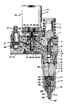
~In the CCLStruCtiOn illustrated, the electro-
magnetic unit fuel injector includes an injector body 1
which includes a vertical main body portion la and a
side body portion lb. The body portion la is provided
with a stepped bore therethrough ~of;ning a cylindrical
lower wall or bushing 2 of an intPrn~l diameter to
slidably receive a pump plunger 3 and an upper wall 4 of
a larger ;rtPrn~l diameter to slidably receive a plunger
actuator follower 5. The follower ~ extends out one end
of the body 1 whereby it and the plunger connected
thereto are adapted to be reciprocated by an engine
driven cam or rocker, in the manner shown schematically
in Figure 2, and by a plunger return spring 6 in a
convPnti~n~l manner. A stop pin 7 extends through an
upper portion of body 1 into an axial groove 5a in the
follower 5 to limit upward travel-of the follower.
The pump plunger 3 forms with the bushing 2 a
pump chamber 8 at the lower open end of the bushing 2,
as shown in Figure 1.
Forming an extension of and threaded to the
lower end of the body 1 is a nut lO. Nut 10 has an
opening lOa at its lower end through which extends the
W096/04475 .~~
21 9~6~4
lower erd of a c ;n~ injector valve body or spray tip
11, hereinafter referred to as the spray tip, of a
conventional fuel injection nozzle assembly. As shown,
the spray tip 11 is enlarged at its upper end to provide
a ~m~ r lla which seats on an internal ~nl ~r lOb
provided by the through rcllnt~rhore in rut 10. Between
the spray tip 11 and the lower end of the injector body
1, there is positioned, in sequence starting from the
spray tip, a rate spring cage 12, a spring retainer 14
and a director cage 15, these ~lFmPntS being formed, in
the construction illustrated, as separate elements for
ease of manufacturing and assembly Nut 10 is provided
with ;ntGrn~l threads 16 for mating eny~"~ L with the
~t~rn~l threads 17 at the lower end of body 1 The
threaded connection of the~nut 10 to body 1 holds the
spray tip 11, rate spring cage 12, spring retainer 14
and director cage 15 clamped and stacked end-to-end
between the upper face llb of the spray tip and the
bottom face of body 1. All of these above-described
Gl' ~ have lapped mating surfaces whereby they are
held in pressure sealed relation to each other
Fuel, as from a fuel tank via a supply pump
and conduit, not shown, is supplied at a predet~rm;n~
relatively low supply pressure to the lower open end of
the bushing 2 by a fuel 8upply passage means which, in
the construction shown, includes a conv~nt;~n~l aper-
tured inlet or 8upply fitting 18 which is threaded into
an ;nt~rn~lly threaded, vertical, blind bore, inlet
passage 20 provided adjacent to the outboard end of the
side body portion la of the injector body l As best
seen in ~igure 1, a convertional fuel filter 21 is
suitably positioned in the inlet passage 20 and retained
by mean8 of the supply fitting 18. A second internally
threaded, vertical blind bore in the side body portion
~ W096l0447S 2 ~ 9 5 6 5 4 l ~l/u~
-7-
la (not shown) spaced from the inlet passaye 20 defines
a drain passage with a fitting threaded therein, for the
return of fuel as to the fuel tank, also not shown.
;
Ir, addition and for a purpose to be described
in detail hereinafter, the side body portion la is
provided with a stepped vertical bore therethrough which
defines a supply chamber 38 and an 1ntrrm~fl1~te or valve
stem guide wall 26, terminating at valve seat 32. A
second through bore, parallel to but spaced from the
valve stem guide wall 26 and P~t~nfl;ng from fuel supply
chamber 38 defines a pressure eriualizing passage 34
opening into a~spill shamber 46, which is closed by a
closure cap 40.
The inlet passage 20 communicates via a
horizontal inlet conduit 47 and a co~necting upwardly
~nrl ;n~ inlet conduit 48 that breaks through the wall
25 with the supply/cavity 38 and the drain passage
communicates via a downwardly ; nrl; n~fl drain conduit 50
(shown in Figure 2 only) with the spill cavity 46, this
conduit opening through wall 27 into the spill cavity.
A passage 51 provides for the ingress and
egress of ~uel to the pump chamber 8 opening into the
pump chamber 8 at the upper end of the injector body.
Fuel flow between ~he 9pill cavity 46 and
passage 50 ls controlled by means of a solenoid actuat-
ed, pressure b~l~nr~fl valve 55, in the form of a hollow
poppet valve. The valve 55 1nrlllfl~ a head 56 with a
co~ical valve seat surface 57 thereon, and a stem 58
P~t~n~;ng upward therefrom. The valve 55, is normally
biased i~ a valve opening direction, downward with
reference to ~igure 1, by means of a coil spring 61
W096/04475
21 95654
loosely encircling valve stem 58. As shown, one end of
the spring abuts against a washer-like spring retainer
62 encircling stem portion 58. The other end of spring
61 abuts against the lower face of a spring retaine~ 35
~JV~I~L~ of the valve 55 in valve closing
direction, upward with reference to Figure 1, is effect-
ed by means of a solenoid assembly 70 which includes an
armature 65 having a stem 66 depending centrally from
its head. Armature 65 is secured to valve 55.
The solenoid assembly 70 further includes a
stator assembly, generally designated 71, having a
flanged inverted cup-shaped solenoid case 72. A coil
bobbin 74, supporting a wound solenoid coil 75 and, a
segmented multi-piece pole piece 76 are supported within
the solenoid case 72.
The solenoid coil 75 is connectable, by
electrical conductors, not shown, to a suitable source
of electrical power via a fuel injection electronic
control circuit, not shown, whereby the solenoid coil
can be energized as a function of the operating condi-
tions of An Long;nL~ in a manner well known in the art.
During a pump stroke of plunger 3, fuel is
adapted to be discharged from pump chamber 8 into the
inlet end of a discharge passage means 80 which admits
pressurized fuel to the spray tip 11 via lines 87, 91,
93 to be injected through spray ~r; ~; rrFL 97 as needle
valve 95 opens against the bias of spring 104 as ex-
plained further in U.S. Patent No. 4,392,612.
Fuel is drained back to the supply/valve
spring cavity 38 via an inrl;nr~ passage llO~in injector
~ w096/04475 2 1 9 5 6 5 4 . ~lIU~
~- ..,i. .
_g_
body 10 which opens at its lower end into a cavity lll
de~i~ed by the ;nt~rnAl wall of the nut and the upper
end of director cage 15 and at its upper end open into
an annular groove 112 encircling plunger 3 and then via
5an in~l ;n~d passage 114 for flow communication with the
supply/valve spring chamber 38
Further details of the structure and operation
of the injector may be obtained from U.S. Patent No.
4,392,612, assigned to the assignee of the present
10application, which is incorporated herein by reference.
Figures 3 through 4 show in detail the struc-
ture of the two-piece plunger 3. It will be noted that
there exists a certain pr~t~rm;n~ rl ~ArAncp 120
between the outer walls of the plunger and the adjoining
15walls of the injector body 1. A minimum clearance is
~;rAhle, i.e. a gliding fi~, particularly in the
region _ since it is important the pressurized fuel be
sealed from escaping the injector housing other than
through drain 110. The plunger includes a cylindrical
20: piston 121 ~nnnt~rhnred along its longitudinal axis a
sign;~inAnt depth so as to tPrm;nAte at the lower ~h
portion of the piston or at a point where the length to
diameter ratio between the end 122 of the piston head
123 and the stop A~m~ r 124 formed at the end of the
25bore 125 is at a ratio less than approximately 2:1.
. The pIunger also ;nnlll~s a push rod 128
having a radially enlarged head 129 and a reduced
diameter stem portion 130 ~t~n~;n5 from the underside
of the head to a point in contact with the stop shoulder
~ 124 of the piston. The cylindrical outer surface of the
stem portion 130 is less than the internal diameter of
bore IZ5 to provide a predetermined clearance 131. The
W096/0447s r~
21 95654
--10 -
amount of this clearance is sized so as to be equal to
or slightly greater than the maximum radial GTp~n~;nn of
the push rod when subjected to compression forces to be
expected under normal operating conditions. A split
locking ring 132, shown in Figures 3 and 4, may be used
to lock the push rod axially within the piston. The
locking ring is adapted to be loosely held in the
locking groove 133 of the piston prior to insertion of
the push rod. When inserted, the push rod will spread
the locking ring until it falls into place within a
similar radially opposing locking groove 134 located in
the push rod, where it will be held in fixed axial
position.
During normal o~r~t;nn, as the plunger
actuator 5, as seen in Figures 1 and 3, forces the
plunger downward against the bias of spring 6, the fuel
in pump chamber 8 will be compressed and brought to very
high fuel pressures, in the o~der of 25,000 to 28,000
psi. This pressure will not be relieved until needle
valve 95 opens and allows fuel to be injected through
the spray nr;f;r~r 97. Even then the pressure developed
within the fuel chamber is not subst~rt;~lly reduced.
Thus, there is always a fairly high pressure within the
fuel chamber and, consequently, a sirn;~;r~ntly high
compressor force is subjected on the plunger throughout
at least all of the pump stroke. In convPnt; nn~l
practice, even with a conv~nt;nn~l solid plungar as
shown in Figure 5, the compressive force at these high
pressures causes the plunger to expand as indicated by
the arrows 140 thereby reducing the rl ~r~nro between
the plunger and the housing at region A, sometimes to
the point of interference. This causes scoring along
the plunger and cylinder walls, as well as premature
failure of the injector. Nith the two-piece plunger as
~ w096/~447s 2 ~ 9 5 6 5 4 i~l/U~
~.' '' ,
- --11-
shown in Figures 1, 3 and 4, the push rod is allowed to
radially expand under this compressive force but its
radial expansion has no effect on ~-;ntA;n;ng the
constant ou~er diameter of the piston. All force is
transmitted from the head 129 of the push rod through to
the stop shoulder 124, the r~mA;r;ng length of the
piston, i.e. the length of the piston head 123, is sized
relative to the diameter of the piston to preclude any
appreciable PY~nR; ~n .
Referring now to Figure 6 of the drawings,
there is shown an additional : ,o~; t injector of the
present invention. ~For convenience, like numerals are
used to describe like components and features of t.he
present i~vention as were used in reference to the
embodiment of Figures 1-4. Illustrated is an electro-
magnetically actuated unit fuel pump and injector
assem.bly having a pump body 1 and a separate injector
valve body or spray tip nozzle 11 connected to the
output side of the pump by high pressure fuel line 157.
The body 1 is provided with a stepped bore ~t~n~; ng
along a longitudinal axis thereof, a portion of the bore
~f;n;ng a firgt cylindrical wall, or bushing, 150
having an ;nt~rnAl ~;~m~t~r configured to slidable
receive a pump plunger 3 and another portion thereof
defining a second cylindrical wall, or bushing, 151
having a larger ;nt~rn~l diameter configured to slidably
receive a plunger actuator follower 5 that drives the
pump plunger 3. The follower~5 is operably accessible
through an open lower end of the body 1, whereby it and
the pump plunger 3 are adapted to be reciprocated by an
engine-driven cam 152, or its e~uivalent, and by a
plunger retu-rn spring 6.
W0 96/04475 I ~
21 95654
-12-
A portion of the stepped bore ~f; n;ng the
first bushing 150 forms, with the pump plunger 3, and at
an end of the first bushing most distant from the second
bushing 151, a pump chamber 8 having a slightly larger
;ntarnAl diameter than that of the first bushing 150.
A bypass passage 154 provides a path to drain fuel that
is forced past the pump plunger 3
A discharge passage means 80 extends from the
pump chamber 8, around an annularly recessed portion of
a valve stem 58 of a pressure h~l ~nrr-~ fuel control
valve, generally ;rA;r~t~d by reference numeral 55, to
a fuel outlet port 153 in an upper end of the body 1.
The valve 55 is actuated by a solenoid assembly, gener-
ally indicated by reference numeral 70, a valve head 56
formed at an end of the valve stem 58 being controllably
~orced against an opposing valve seat surface 57 by the
solenoid assembly 70. The configuration of the annu-
larly recessed portion of the valve stem 58, however,
provides a path for fuel flow regardless of how the
valve stem is positioned by the solenoid assembly 70.
The outside diameter of the pump plunger 3 is
slightly smaller than the inside diameter of the first
bushing 150, thus providing a clearance 120 therebe-
tween. The pump plunger 3 includes a cylindrical piston
121 having a bore 125 P~t~r~;ng along a longitudinal
axis thereof, the bore:being nearly the length of the
piston 121, terminating at a stop shoulder 124 and
leaving a closed end 122 forming a piston head 123
proximate the pump chamber 8. ~ ~
The pum~ plunger~3 also ;nrln~rr a push rod
128 having at one end a head 129 resiliently biased
against the plunger actuator follower 5 by the plunger
~W096104475 2 1 95654 I~J/.J~5 ~l
-13-
return spring 6 through an interlocked return spring
retainer member 135. A portion of the other end of the
push rod 128 has an outside diameter that is slightly
smaller~than the inside diameter of the bore 125, thus
providing a clearance 131 therebetween and allowing this
portion of the push rod to be slidably received within
the er,tire length of the bore 125. The clearance 131 is
that amount calculated to be e~ual to or slightly
greater than that re~uired to ~ttt a~te the maximum
t~pecrt~A radial expansion of the push rod 128 while the
latter is subjected to axial compressive forces under
normal opt~r~t;ng conditions.
The inner wall of the bore 125 in the piston
121 is recessed to form an annular locking groove 133 to
receive and loosely hold a split locking ring 132. The
portion of the push rod 128 that is to reside within the
bore 125 is also recessed to form an annular locking
groove 13i axially positioned such that, as the push rod
is being inserted, the locking ring, having been spread
during the insertion, will snap into the locking groove
134 in the push rod just as the push rod contacts the
stop ~hml1tlt~r 124, ~;nt~;n;ng the axial position of the
latter fixed with respect to that of the piston 121, all
as described in tnnnt-rtjnn with Figure 4. A stem
portion 130 of the push rod 128 extends between the
inserted portion and the head 129 ~hereof.
During normal operation, fuel, as from a fuel
tank via a supply pump and conduit, not shown, is
supplied at a relatively low supply pressure to an inlet
passage 20 in the injector body l and is drawn into the
pump chamber 8 by a suction stroke of the pump plunger
3. ~s the plunger ~ntl1~tnr follower 5 forces the pump
plunger 3 upward, as shown in Pigure 6, against the bias
W096/04475 r~
21 q5654
-14-
of the plunger return spring 6, the fuel in the pump
chamber 8 will be forced, under very high preEsure, from
the pump chamber 8, through the discharge passage means
80, and through the fuel outlet port 153. The fuel
pre89Ure i8 on the order of.25,000 to 28,000 psi.
Although the transfer point of the force
exerted by the push rod 128 against the stop ~hm1l~Pr
124 of the piston 121 is within the first bushing 150
while the piston is in a fully or almost fully retracted
position, it is in the pump cham~er 8 by the time a high
load is established. The pump chamber 8, having a
larger diameter than that of the first bushing 150, can
ac~ -~~te a greater amount of radial P~pAn~inn near
the end of the piston 121 While the piston 121 is
within the first bushing 150, the load is sufficiently
low to prevent the piston from radially P~pAn~;ng
sufficiently to cause interference with the first
bushing.
While the best mode for carrying out the
invention has been described in detail, those familiar
with the art to which this invention relates will
recognize various alternative designs and emoodiments
for pr~t;n;ng the invention as defined by the following
claims.