Note: Descriptions are shown in the official language in which they were submitted.
BACkGROLiND OF 'IIiE INVENTION
Field of the Invention
T'he invention relates to a housin« for receiving individual components of a
heaCing or
cooling installation.
Biscussion of the Prior Art
For cladding and thermal insulation of pipelines, one-piece coverings, matte
from
thermally insulating ruatcri:zl in the form oFcylindrical jackets, <are slid
over the lines in a known
maimer. The coverings may be several centimeCers thick. Because of its. one-
piece constmction,
this cladding has a very favorable heat insulating capacity. Heat bridges such
as occur when two
shells are butt j<»nted are prevented to a great extent. However, this
cladding can be fitted only
by sliding it over the pigeline from a free end of the pipeline. The cladding
is noC suitable for
subseduently providing an already installed heating installation with heat
insulation. For gige
inspection purposes, such coverings must be cut along their length. The cut up
coverings can
be reused only at the expense of a diminish c;d heat insulating capacity.
For these reasons, hall'-shells which are connected by a 'butt joint aC Cheir
cormecting
locations have also been used as thermally insulating coverings for pigelines.
To hold the shells
together, the joint location is covered va-ith an adhesive strip connecting
the outer surface areas
of the Cwo halt-shells along floe joint IocaCion. Although this design enables
subsequent fitting
1
~'1 ~~~~;.~
of cladding and inspection of pipelines, it requires a eotnpl.icated and time-
consuming gluing of
the joint location. In addition, a huff joint. always poses the risk c?f
unwanted heat transfer.
Finally, in a known manner, piping, connections and fittings i>f a heating or
cooling
installation which are combit2ed in ready-to-install structural components are
accommodated in
a housing comprising rive half-shells made from heat-insulating plastic, in
particular expanded
polypropylene. In order to close the two half-shells simply and quickly and to
prevent heat
bridges, the joint area is not flush but, instead is constnrcted in the form
of a single-undercut
mortise or rabbet on one haft-shell and a corresponding gro<?ve on the other
half=shell (EF' 0 561
037 AI). When the two half-shells are pressed together, a snapping in and
interlocking take
place via the undercut surfaces.
In irrder for the two half-shells to lae pressed together enabling the
undercut surfaces to
snap together, the undercut raibbets lying at right angles to the movement
direction of the half=
shells must be placed exactly one upon the other by their planar partial
surfaces, since the
vertical pressuri; ti> he applied for snapping in must cause <r yielding
Howard the side exclusively
by means of tha elasticity of the rustterial si? that the ed~~e of the upper
rabbet can slide over Chat
of the lower rabbet. This accuracy of position c<ut often not lie accomplished
in the held. If
tktis is not achieved, tilting will cause the rabbet connection to snap in of
one edge but not at the
opposite edge which results in an incomplete enclosure of the pipe.
7
2?~~~~~
SLIMllWAItY OF 'CHE INVENTION
Accordingly, it is an object of the present invention to provide an insulating
housing in
which the cotmection area is constructed so tlrtut the individual shell-type
housing parts can be
put together quickly arnd easily so as to form a self-locking connecti<m which
extensively
prevents heat losses.
Pursuant to this object, and others which will become aplrtrent hereafter, one
aspect of
the present invention resides in a hi>using comprised of at least. two shells
of thermally insulating
plastic which are configured to enclose heating and cooling components between
the shells. 'fhe
shells, respectively" have facing edges. Rabbet connection means are arranged
on the facing
edges of the shells and include a rabbet strip on the facing edges of a first
one of the shells and
a groove strip corresponding iu shape and dimension to the rabbet strip on the
facing edges of
a second one of the shells. The rztbbet strip is engagable with the groove
strip so than the shells
interlcxk positively along a cimtactin~~ plane. The groove strip of the second
shell bus a flank
that is divided into au upper partial surface which is inclined relative to
the rabbet strip at an
angle a to a normal line, and a lower partial surface which is inclined at an
angle I3 ti> the
norntal line. The eagles a and 13 have opposite rotational directions. The
rabbet strip of the
first shell htrs surfaces configured to correspond to the upper and lower
partial surfaces of the
groove strip.
The basic idea of the invention is that a guide surface is provided in
addition to the
undercut locking surface of the rabbet. When two half-shells are pressed
together, the lower
inner edge of the rabbet strip first encounters the inclined guide surface of
the groove at the
3
21 ~~~3~r~
other half-shell unit slides along it. Tn so doing, a gradual elastic widening
of the rabbet strip
is effected. In passing from the guide surface to the lockin, surface, the
rabbet sC.rip snaps into
the locking surface due to iGS elastic bet vior and holds the two half-shells
Cogether. During this
process, the circumferentially extending guide surface at the carne time
centers the half-shells
relative to one another. Accordingly, the half-shells ncn longer need to lie
exactly one above the
i>tlrer when assembling the ltousing; it is sufficient that the rabbet strip
lie in the region of the
guide surface. This substantially facilitates the closing of the housing.
'the construction of the rabbet connection according ti> the invention further
ensures that
the rabbet connection will not tae overworked by excessive bending of material
in the face of
repeated closing and opening of the shells as required for repair and
inspection.
A firrther advantage of the inventive construction is that no continuous gap
eau be formed
ai the joint due Co the connbir>irtion of locking and guiding sutfiaces. At
least one of the two
surfaces contacts the other half-shell by its corresponding mating surface.
The risk of a heat
bridge in the butt joint is accordingly eliminated.
Furthermore, manufacturing! toleranees caused by slnrinhage are compensated
for by this
construction of the rabbet connection.
The; various features of novelty which characterize the invention are pointed
out with
particularity in the claims amiexed to and forming as part of the disclosure.
For a better
understanding of the invention, its operating advantages, and specific objects
attained by its use,
reference should be had to the drawing and descriptive nnatter in which there
are illustrated and
described preferred embodiments of the invention.
4
BRIEF DESCRIPTION OF THE I)RAW'ING
In the drawim~:
Fig. 1 is a perspective view of a housing used for thermal insulation of
pipelines;
Pig. ? is a cross section thrau'sh a thin-walled embodiment of a housing
according to the present invention;
Fig. 3 is an enclosed detail III through a rabbet cottnection according to the
invention itt Fin. 2,; and
Figs. 4 to 7 are cross 'sectional views of additional embodimc.nCs of the
rabbet
connection.
2~~5~4~
DETAILED DESCRIPTION OF"f1~IE I'RFI'ERRED EMBODIMENTS
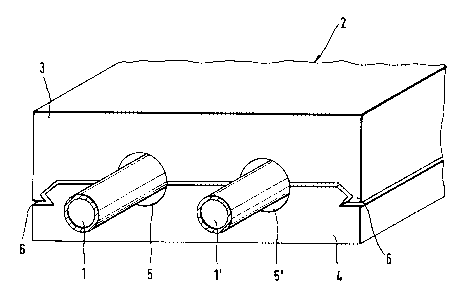
Fig. 1 shows the invention used as thermal insul<rtian for pipelines. The
figure shows
two pipelines 1, 1' in which a heating or cooling medium circulates. The two
pipelines 1, 1'
are embedded in a housing 2 made of thermally insulating material to prevent
energy losses
caused by a transfer of heat or cold to the environment. Expanded
polypropylene (EPP) is
particularly suitable as the thermally insulating material; however, expanded
polyethylene (EPE),
polystyrene {EPS), or the like, are a'Iso possible.
Apart from the thermal insulation capacity, other important material
characteristics
include strength, which determines the ttrrces which can f>e transmitted into
the cirrtnection joint,
and elasticity which is a necessary condition for autonratii: locking.
In the embodiment shown ut the drawing, the housing 2 is formed of two solid-
walled
half-shells, in this instance a top half-shelf 3 and a bottom hadf-shell 4
which lie one on top of
the other along the greater part of their surface. Each of the two half-shells
3, 4 receives half
of tire pipeline 1, I' itt cut out portions 5, ~' expressly provided for that
purpose. 'phe half-
shells 3, 4 are connected with one tvnc.~ther at the edges in a positive and
frictional engagement
via a rabbet connecti<rn 6 shown in larger scale in Fi~=. 3.
Fig. 2 shows another embodinti:nt of a housing 7 according to the invention.
In this case,
also, the lurusing 7 is formed of a tire shell 8 and a bottom shell 9. In
contrast to the housing
2 described in Fig. I, however, the half-shells 8, 9 are thin-walled and
enclose a hollow space
10. For cxatnple, a ready-to-install structural component group of a heating
installation may be
arranged in tFtis cavity 10. 'The top shell 8 and bottom shell 9 are
corutected with one another
C
~~~i~~~e
at their shared contact face in a positive and frictional engagement by means
of a rabbet
construction 11 according to the invention.
Fig. 3 is a detail III of Fig. 2, showing the connection point between the
ti>p shell H and
bottom shell 9 in enlarged scale. At tyre shared contacting surface of the two
half=shells 8, 9,
the bottom shell 9 has a groove strip 12 and the top shell 8 has a rabbet
strip .13 cotxeslsonding
to the groove strip 12. In it.s base region, the flank 14 of the groove strip
12 of the bottom shell
9, which cooperates with the rabbet strip 1._>, comprises a locking surface 16
which is inclined
relative to the rabbet strip 13 at an angle ~3 to the normal fine 15 and a
guide surface 17 which
adjoins the locking surface 1(i so as to be inclined in the opposite direction
at an angle a to the
normal line 15. 'f Ite ratio of dimensions of the locking surface 16 to the
guide surface 17 can
vary depending on the intended use. In the e~xntple shown, the tvvo surfaces
16 and 17 and both
angles a and (3 are the same size. 'lf the holding capacity of the comrection
is of secondary
importance compared with a simple and easy closing of the housing 7, the guide
surface 17 can
be increased at the expense of the locking surface 16 by selecting a smaller
angle of inclination
rx while 'keeping constant the height h of the rabt,ct. This also holds true
in the reverse case.
'1 he construction <>f the rabbet strip I S of tire fop shell $ cotmesponds to
that c>f the groove
strip 12 with respect is shape and size. Like the inclination angles a and E>
of the guide swl'ace
and locking surface 16, 17, respectively, and the distance <t between the
rabbet edges determined
thereby, the width h of the rabbet strip 13 xt the mtrrowest pc»nt and its
height It are so
dimensioned that a snap-in effect can be achieved depending on fhe elasticity
and restoring forces
of the material used without the material wearing out after frequent opening
and closing of the
housing 7. Tlre lower corner 1R of the rabbet strip 13 is ctdvisxblp somewhat
rounded.
7
CA 02195840 2000-03-21
' 21182-309
Fig. 4 shows an embodiment of the rabbet connection
as an alternative to that shown in Fig. 3. In this case, the
flank 21 of the groove strip 20 cooperating with the rabbet
strip 19 is convex so that the upper half of the flank 21 forms
the guide surface 22 and the lower half of the flank 21 forms
the locking surface 23 which adjoins the guide surface 22, so
that the guide surface 22 and the locking surface 23 have an
equal curvature and pass into one another in a continuous
manner. This connection works in a manner corresponding to
that of the embodiment form shown in Fig. 3 so that the
dimensions of the rabbet must also in this instance be so
adapted to the material characteristics that the deformation
occurring when closing and opening remains in the elastic
range.
If the locking forces between the top shell 8 and
bottom shell 9 are not expected to be sufficient, the rabbet
connections shown in Figs. 3 and 4 can also be constructed
symmetrically in order to increase these forces. In so doing,
the locking surface 24, which is decisive for the composite
action, is doubled. Fig. 5 shows such an embodiment. The
rabbet strip 25 slides along the guide surfaces 26 when the
half-shells 8 and 9 are pressed together as a result of the
modified dovetail construction of the groove and rabbet strip
25. For this purpose, the two pointed ends of the dovetail-
shaped rabbet strip 25 are partially elastically flattened and
partially bent until passing the narrowest point of the groove
which is likewise dovetail-shaped. Only then is it possible to
snap into the locking surfaces 24 due to the restoring forces
of the material. A connection of this type naturally occupies
more space in the joint direction than the single construction,
but prevents a possible deformation of the shells 8 and 9 which
could occur when snapping in. For this reason, it is
8
CA 02195840 2000-03-21
21182-309
especially suitable for the types of housing described, e.g.,
in Fig. 1.
In the examples shown, the groove and the rabbet
strip engage one inside the other in accordance with the
principle of a male and female mold for the meshing of the
surfaces, the
8a
~ a';~~(~
raised Ix3rtions occurring in the flank surface of the groove. It is also
possiblz to Ytave rabbet
connections whose raised portions are arranged in the rabbet strip and engage
in depressions in
the groove and thus result in a locking <7f the half-shells. Figs. 6 and 7
show examples of such
constructions. With respect to operation, Fish. 7 corresponds to Fig. 4 and
Fig. G corresponds
to Fig. 5.
The invention is n<>t limited by the embi>diments described above which are
presented ;as
examples only but can be modified in various ways within the scope of
protection defined by the
appended patent claims.
9