Language selection

Search

Patent 2196515 Summary

Third-party information liability

Some of the information on this Web page has been provided by external sources. The Government of Canada is not responsible for the accuracy, reliability or currency of the information supplied by external sources. Users wishing to rely upon this information should consult directly with the source of the information. Content provided by external sources is not subject to official languages, privacy and accessibility requirements.

Claims and Abstract availability

Any discrepancies in the text and image of the Claims and Abstract are due to differing posting times. Text of the Claims and Abstract are posted:

  • At the time the application is open to public inspection;
  • At the time of issue of the patent (grant).
(12) Patent: (11) CA 2196515
(54) English Title: DRAWER
(54) French Title: TIROIR
Status: Expired and beyond the Period of Reversal
Bibliographic Data
Abstracts

English Abstract


A drawer slide which forms a side wall of a drawer has outwardly curving
holding devices in the form of a first shoulder projection with a tab and a
second
shoulder projection offset to one another in a back wall area of the drawer
slide which
engage in corresponding bore holes of a back wall and secure the back wall
against
shifting.


Claims

Note: Claims are shown in the official language in which they were submitted.

CLAIMS:
1. A drawer component comprising a drawer slide which forms a
side wall of a drawer, the drawer slide having a back wall area and a
front wall area, wherein the drawer slide has outwardly curving holding
devices in the back wall area of the drawer slide adapted to engage in a
back wall and adapted to secure the back wall against shifting in
vertical and horizontal directions, the holding devices including a tab
bent out of the back wall area of the drawer slide substantially
perpendicular to the drawer slide, with a first shoulder projection
formed on the bent tab, the first shoulder projection extending
substantially perpendicular to the bent tab toward the front wall area of
the drawer slide and being adapted to engage in a corresponding bore
hole of the back wall, and a second shoulder projection bent out of the
back wall area of the drawer slide and extending substantially
perpendicular to the drawer slide and likewise adapted to engage in a
corresponding bore hole in the back wall.
2. A drawer component according to claim 1, wherein a drawer
bottom rests in a lower area of the back wall and additionally prevents
horizontal shifting.
3. A drawer component according to claim 1, wherein the first and
second shoulder projections are placed offset in one of a horizontal and
vertical direction.
4. Drawer, according to claim 1, wherein a drawer bottom rests in a
lower area of the back wall and additionally prevents horizontal shifting.
5. A drawer component according to claim 1, wherein said drawer
-10-

slide has a top and bottom, said first shoulder projection is spaced from
the bottom of the drawer slide, and said second shoulder projection is
spaced between the first shoulder projection and the top of the drawer
slide.
6. A drawer component according to claim 1, wherein said drawer
slide has a top and bottom, and the drawer slide has at least one
additional shoulder projection which is formed on the bottom of the
drawer slide and extends substantially parallel to the drawer slide
toward the top of the drawer slide, and which is spaced between the
front wall and back wall areas of the drawer slide and adapted to
engage a drawer bottom.
7. A drawer component according to claim 1, wherein said first
shoulder projection engages a first bore hole formed on a back side of
the back wall extending parallel to the drawer slide, and the second
shoulder projection engages a second bore hole formed in an end of the
back wall extending perpendicular to the drawer slide.
-11-

Description

Note: Descriptions are shown in the official language in which they were submitted.


CA 02196515 2005-02-25
Drawer
The described drawer is well suited for quick assembly, and, especially
for the "tool-free" assembly (no tools required) of a drawer back wall
made of wood.
A drawer of this type, for example, was made known by the disclosure
publication DR 27 02 217. This document describes a drawer, especially
a drawer side wall, which makes an easy assembly of solid walls,
especially the front, back and bottom walls, possible. The drawer side
wall is formed as a plate type profile rail and has on its front side,
backside and underside, outwardly bent holding devices for the front
walls, back walls, and bottom walls.
A drawer of this type is especially disadvantageous for the fastening of
the back wall, because the holding device for the back wall is formed so
that the back wall is secured against shifting based on the inward
pressure. However, a push or pressure on the outer part of the back
wall results in the back wall shifting or even in the drawer falling in or
collapsing.
-3-

CA 02196515 2005-02-25
The object of the present invention is based on the task of further
developing and improving the aforementioned drawer so that a quick
and secure fastening of the back wall becomes possible and is still
secured against shifting in any direction.
A fundamental feature of the invention is that in the back wall area of
the drawer Zargen slide (side wall) there are holding devices that curve
out from it, and these holding devices engage in the back wall and
secure it against shifting in the vertical and horizontal direction.
This is achieved by the shoulder projections, formed in the back area of
the drawer Zargen slide, which engage in the bore holes of the back
wall. Preferably, two shoulder projections are formed on each Zargen
slide, so that the first shoulder projection engages from behind in the
back wall and the second shoulder projection engages in a
perpendicular direction to the face side of the back wall.
The combined action of both shoulder projections ensures not only that
the back wall is secured against vertical shifting, but also that it is held
steady in the horizontal direction so that inward or outward pressure on
the drawer will not result in shifting.
-4-

,~ 219~~15
Preferably, the holding devices are placed in the horizontal and
also vertical direction. This increases the attainable
stability.
The invention related objectives of the submitted invention
results from not only the matter of the particulars of the
protection claims, but also the various combinations of the
individual protection claims.
All records, documents and evidence, inclusive of the abstract,
open and disclosed statements and declarations and indications
and features, especially those represented embodiments in the
drawings, will be claimed as fundamental and significant
inventions, as far as the claims individually or in combinations
are relative to the position that the technology is new.
The invention at hand will be explained more precisely by the
various embodiments shown by the representational drawings.
Hereby, additional significant features and advantages of the
innovation will be concluded from the designs and their
descriptions.

. ,~ 2196j15
Thereby shown:
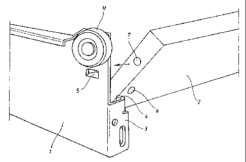
Figure 1: a perspective view of the drawer with the drawer
Zargen slide and back wall during the assembly;
Figure 2: a sectional view -through the drawer along the
lengthwise side of the drawer Zargen slide;
Figure 3: a top view of the drawer Zargen slide;
Figure 4: a front view of the drawer Zargen slide.
Figure 1 shows the drawer, especially the back section of the
drawer, during the assembly of the back wall. One sees the
drawer Zargen slide (1), which is also the drawer side wall, and,
simultaneously, is the guide rail of the drawer. The drawer
zargen slide (1) has in its back area a somewhat rectangular bent
tab (3). On the tab (3) a shoulder projection (4) is curved out,
which points somewhat towards the front side of the drawer.
Furthermore, the drawer Zargen slide (1) has in its back area, a
shoulder projection (5) which, preferably, is bent out of the
material of the drawer Zargen slide (1) itself. This shoulder
projection (5) points into the drawer. Naturally, it is equally
possible to design the shoulder projection (5) as a screw, a
bolt, or a welded-on tab.
The roller track (11} supports the drawer Zargen slide (1) in its
operation as a guide slide.
-6-

2196515
Moreover, one sees the back wall (2) that has a bore hole (6) on
its back side and, preferably, has a bore hole (~) on its side.
It is provided that the shoulder projections (4 and 5) of the
drawer Zargen slide (1) engage in the corresponding bore holes (6
and 7) of the back wall (2), and, thereby, the back wall (2) is
held to the drawer Zargen slide (1).
The back wall (2) consists preferably of wood, but can also be
made of plastic. In order to mount the back wall, the back wall
is placed slightly tilted so that its bottom edge points towards
the drawer space. Then the back wall (2) is placed, face and
back, With the bore holes (7) on the respective shoulder
projection (5). Now the back wall is turned perpendicular. Then
the shoulder projection (4) engages in the back side bore hole
(6) of the side wall (2).
When the drawer bottom (8) is inserted, which is after the back
wall (2} is mounted, the back wall is then even more stabilized.
Please refer to the embodiments in Figures 2 to 4 for additional
clarifications. It should be noted again the drawer Zargen slide
(1} on whose back side area, the shoulder projections (4 and 5)
are formed. These shoulder projections engage in the
corresponding bore holes (6 and 7) of the back wall (2). In the

2~96j~5
same manner, the drawer Zargen slide (1) has on its underside a
shoulder projection (9) which engages in the corresponding bore
hole (10) of the drawer bottom (8). After the drawer bottom is
inserted, it rests in the lower area of the back wall so that the
back wall (2) is then even more protected from shifting.
It should be noted that the shoulder projections (4 and 5) of the
drawer Zargen slide (i) are arranged preferably in the
horizontal, as well as the vertical position, opposing each other
in order to have a better 8ivision of strength and to secure the
back wall (2) sufficiently.
_g_

2~ss~n
Drawings Legend
1. Drawer Zargen slide (side wall)
2. Back wall
3. Tab
4. Shoulder projection
5. Shoulder projection
6. Bore hole
7. Bore hole
8. Drawer bottom
9. Shoulder projection
10. Bore hole
11. Roller track
_g_

Representative Drawing
A single figure which represents the drawing illustrating the invention.
Administrative Status

2024-08-01:As part of the Next Generation Patents (NGP) transition, the Canadian Patents Database (CPD) now contains a more detailed Event History, which replicates the Event Log of our new back-office solution.

Please note that "Inactive:" events refers to events no longer in use in our new back-office solution.

For a clearer understanding of the status of the application/patent presented on this page, the site Disclaimer , as well as the definitions for Patent , Event History , Maintenance Fee  and Payment History  should be consulted.

Event History

Description Date
Inactive: IPC expired 2017-01-01
Time Limit for Reversal Expired 2009-02-02
Letter Sent 2008-01-31
Inactive: IPC from MCD 2006-03-12
Grant by Issuance 2005-09-20
Inactive: Cover page published 2005-09-19
Letter Sent 2005-07-11
Pre-grant 2005-07-07
Inactive: Final fee received 2005-07-07
Inactive: Single transfer 2005-06-10
Notice of Allowance is Issued 2005-05-19
Letter Sent 2005-05-19
Inactive: Approved for allowance (AFA) 2005-04-14
Amendment Received - Voluntary Amendment 2005-02-25
Inactive: S.30(2) Rules - Examiner requisition 2004-11-02
Inactive: S.29 Rules - Examiner requisition 2004-11-02
Inactive: Status info is complete as of Log entry date 2002-02-07
Letter Sent 2002-02-07
Inactive: Application prosecuted on TS as of Log entry date 2002-02-07
All Requirements for Examination Determined Compliant 2002-01-16
Request for Examination Requirements Determined Compliant 2002-01-16
Inactive: Cover page published 1999-10-01
Application Published (Open to Public Inspection) 1998-07-31
Letter Sent 1997-11-28

Abandonment History

There is no abandonment history.

Maintenance Fee

The last payment was received on 2004-12-16

Note : If the full payment has not been received on or before the date indicated, a further fee may be required which may be one of the following

  • the reinstatement fee;
  • the late payment fee; or
  • additional fee to reverse deemed expiry.

Please refer to the CIPO Patent Fees web page to see all current fee amounts.

Owners on Record

Note: Records showing the ownership history in alphabetical order.

Current Owners on Record
GRASS AMERICA, INC.
Past Owners on Record
JOHANNES HAEMMERLE
Past Owners that do not appear in the "Owners on Record" listing will appear in other documentation within the application.
Documents

To view selected files, please enter reCAPTCHA code :


To view images, click a link in the Document Description column. To download the documents, select one or more checkboxes in the first column and then click the "Download Selected in PDF format (Zip Archive)" or the "Download Selected as Single PDF" button.

List of published and non-published patent-specific documents on the CPD .

If you have any difficulty accessing content, you can call the Client Service Centre at 1-866-997-1936 or send them an e-mail at CIPO Client Service Centre.


Document
Description 
Date
(yyyy-mm-dd) 
Number of pages   Size of Image (KB) 
Representative drawing 1998-10-02 1 6
Cover Page 1998-10-02 1 30
Cover Page 1997-05-08 1 12
Abstract 1997-05-08 1 9
Description 1997-05-08 7 178
Claims 1997-05-08 2 37
Drawings 1997-05-08 2 40
Cover Page 1999-10-01 1 30
Description 2005-02-25 7 168
Claims 2005-02-25 2 62
Representative drawing 2005-08-23 1 9
Cover Page 2005-08-23 1 30
Description 2005-09-19 7 168
Abstract 2005-09-19 1 9
Drawings 2005-09-19 2 40
Courtesy - Certificate of registration (related document(s)) 1997-11-28 1 116
Reminder of maintenance fee due 1998-10-01 1 110
Reminder - Request for Examination 2001-10-02 1 129
Acknowledgement of Request for Examination 2002-02-07 1 178
Commissioner's Notice - Application Found Allowable 2005-05-19 1 161
Courtesy - Certificate of registration (related document(s)) 2005-07-11 1 114
Maintenance Fee Notice 2008-03-13 1 172
Correspondence 1997-02-25 1 36
Fees 2002-12-05 1 30
Fees 2002-01-03 1 30
Fees 2000-01-14 1 31
Fees 2004-01-16 1 32
Fees 1999-01-28 1 32
Fees 2000-12-11 1 32
Fees 2004-12-16 1 28
Correspondence 2005-07-07 1 25
Fees 2005-12-21 1 26
Fees 2006-11-01 1 27