Language selection

Search

Patent 2196543 Summary

Third-party information liability

Some of the information on this Web page has been provided by external sources. The Government of Canada is not responsible for the accuracy, reliability or currency of the information supplied by external sources. Users wishing to rely upon this information should consult directly with the source of the information. Content provided by external sources is not subject to official languages, privacy and accessibility requirements.

Claims and Abstract availability

Any discrepancies in the text and image of the Claims and Abstract are due to differing posting times. Text of the Claims and Abstract are posted:

  • At the time the application is open to public inspection;
  • At the time of issue of the patent (grant).
(12) Patent Application: (11) CA 2196543
(54) English Title: CLEANING PRODUCT AND RELATED PACKAGING
(54) French Title: PRODUIT NETTOYANT ET DISTRIBUTEUR POUR LE RECEVOIR
Status: Deemed Abandoned and Beyond the Period of Reinstatement - Pending Response to Notice of Disregarded Communication
Bibliographic Data
(51) International Patent Classification (IPC):
  • A47K 5/13 (2006.01)
  • B65D 23/00 (2006.01)
(72) Inventors :
  • IAIA, MARK JOHN (United States of America)
  • VERDURA, JAVIER JR. (United States of America)
  • DZIERSK, MARK (United States of America)
(73) Owners :
  • UNILEVER PLC
(71) Applicants :
  • UNILEVER PLC (United Kingdom)
(74) Agent: SMART & BIGGAR LP
(74) Associate agent:
(45) Issued:
(86) PCT Filing Date: 1995-07-08
(87) Open to Public Inspection: 1996-02-15
Examination requested: 2002-05-07
Availability of licence: N/A
Dedicated to the Public: N/A
(25) Language of filing: English

Patent Cooperation Treaty (PCT): Yes
(86) PCT Filing Number: PCT/EP1995/002710
(87) International Publication Number: WO 1996004175
(85) National Entry: 1997-01-31

(30) Application Priority Data:
Application No. Country/Territory Date
08/283375 (United States of America) 1994-08-01

Abstracts

English Abstract


A cleaning product and system is described that includes a fluid cleaning
composition, a dispenser (2) for holding the composition and a wall mount (4)
that receives and supports the dispenser (2). An engagement mechanism, such as
a curved recess (20) in respective parallel side walls of the dispenser,
functions to support same within a U-shaped bracket (22) of the wall mount.
The bracket (22) includes left and right arms (30) parallel to one another
projecting outwardly and form-fittingly coupling with the recesses (20) on the
dispenser side walls. A suction cup (32) is joined to a rear surface (28) of
the bracket (22) functioning to attach the wall mount (4) to a wall.


French Abstract

On décrit un produit nettoyant et un système qui comprend une composition nettoyante fluide, un distributeur (2) pour recevoir la composition et un support mural (4) pour soutenir le distributeur (2). Un moyen d'engagement, tel qu'un creux courbe (20) dans des parois latérales respectives du distributeur, permet d'engager celui-ci sur un élément en forme de U (22) du support mural. L'élément en U (22) possède un doigt gauche et un doigt droit (30) qui sont parallèles en faisant saillie vers l'extérieur pour constituer un dispositif de couplage s'adaptant de près au creux (20) des parois latérales du distributeur. La surface arrière (28) de l'élément en U (22) porte une ventouse (32) permettant de faire tenir le support mural (4) sur un mur.

Claims

Note: Claims are shown in the official language in which they were submitted.

CLAIMS
1. A cleaning product comprising:
(i) a fluid cleaning composition:
(ii) a dispenser for holding said cleaning composition
comprising:
a front wall, a rear wall, a closed end wall, a dispensing
end wall opposite the closed end wall and a pair of side
walls in combination defining a container;
a dispensing opening formed in said dispensing end wall of
said container; and an engagement means for supporting said
container, said engagement means being unitarily formed as
identical structures on each of said side walls at a position
along a length thereof closer to said closed end wall than to
said dispensing end wall; and
(iii) a wall mount for receiving and holding said container
comprising:
a U-shaped bracket comprising:
a back plate with front and rear surfaces;
left and right arms parallel to one another, each projecting
perpendicularly from said front surface of said back plate
and structured to form-fittingly couple with said engagement
means;
a suction cup joined to said rear surface of said back plate
for attaching said wall mount to a wall.

2. A product according to claim 1 wherein said engagement
means is a recess fashioned into said side wall.
3. A product according to claim 1 wherein said bracket
further comprises a retaining tab on each of said arms
projecting perpendicularly away from said respective arms and
one of said retaining tabs oriented toward said other one.
4. A product according to claim 3 wherein said retaining
tab is positioned at an end of said arm distant from said
back plate.
5. A product according to claim 1 wherein said back plate
of said wall mount on said front surface near a lower edge
thereof includes a support chin protruding outwardly
therefrom.
6. A product according to claim 1 wherein at least a major
portion of each of said arms is contoured to present an
elongated convex surface.
7. A product according to claim 6 wherein said major
portions of said arms each are facingly juxtaposed one to
another.
8. A product according to claim 1 further comprising a rear
support projecting perpendicularly outward from said rear
surface of said back plate.
9. A product according to claim 8 wherein said rear support
is a curved ridge oriented along a lower edge of said back
plate.
10. A product according to claim 1 wherein all of said wall
mount, except for said suction cup, is unitarily constructed.

11. A product according to claim 1 wherein said fluid
cleaning composition comprises from 0.1 to 60% of a
surfactant.
12. A dispensing system comprising:
(i) a dispenser for holding a cleaning composition
comprising:
a front wall, a rear wall, a closed end wall, a dispensing
end wall opposite the closed end wall and a pair of side
walls in combination defining a container,
a dispensing opening formed in said dispensing end wall of
said container; and
an engagement means for supporting said container, said
engagement means being unitarily formed as identical
structures on each of said side walls at a position along a
length thereof closer to said closed end wall than to said
dispensing end wall; and
(ii) a wall mount for receiving and holding said container
comprising:
a U-shaped bracket comprising:
a back plate with front and rear surfaces;
left and right arms parallel to one another, each projecting
perpendicularly from said front surface of said back plate
and structured to form-fittingly couple with said engagement
means;
a suction cup joined to said rear surface of said back plate

11
for attaching said wall mount to a wall.
13. A system according to claim 12 wherein said engagement
means is a recess fashioned into said side wall.
14. A system according to claim 12 wherein said bracket
further comprises a retaining tab on each of said arms
projecting perpendicularly away from said respective arms and
one of said retaining tabs oriented toward said other one.
15. A system according to claim 14 wherein said retaining
tab is positioned at an end of said arm distant from said
back plate.
16. A system according to claim 12 wherein said back plate
of said wall mount on said front surface near a lower edge
thereof includes a support chin protruding outwardly
therefrom.
17. A system according to claim 12 wherein at least a major
portion of each of said arms is contoured to present an
elongated convex surface.
18. A system according to claim 17 wherein said major
portions of said arms each are facingly juxtaposed one to
another.
19. A system according to claim 12 further comprising a rear
support projecting perpendicularly outward from said rear
surface of said back plate.
20. A system according to claim 19 wherein said rear support
is a curved ridge oriented along a lower edge of said back
plate.

12
21. A system according to claim 12 wherein all of said wall
mount, except for said suction cup, is unitarily constructed.

Description

Note: Descriptions are shown in the official language in which they were submitted.


~ WO961Q4175 21 1~5~3 r~ 75~ o
C~EANING PRODUCT ANn RT~T,~TEn PACKAGINC
~ The invention concerns a cleaning product including a
cleaning composition held in a dispenser supportable on a
~ 5 wall mount. More particularly, the invention relates to
bottom delivery packages for storing and dispensing viscous
fluid materials such as shampoos, conditioners, soaps and
detergents.
sottOm delivery packages having self-sealing valves for
storing and dispensing fluid materials such as shampoos,
conditioners, soaps or detergents are generall~ known in the
art. The use of a self-sealing val~e eliminates the need to
operate a removable closure when dispensing the product.
Typically the self-sealing valve has a closed position for
preventing any discharge of fluid through the valve when not
in use, and an open position to dispense fluid through the
valve upon the application of ~anual s~ueezing forces.
Many bottom delivery packages of the known art do not include
a means to hang the package from a support. The package must
therefore be picked up and placed down every time it is used.
This is inconvenient for the consumer. Some products do
include hangers or apertures near top areas of the package to
engage a shower head, wall handle or other support.
U.S. Patent 4,728,006 (Drobish et al.i exemplifies a bottom
delivery package having a self-sealing ~alve that can be hung
from a hook, shower head or other support. The package
disclosed in Drobish has a recessed notch or a hook integral
with the package so as to suspend the package on a shower
head in an inverted position.

WO9~175 r~ "o
4 3
There are disadvantages in having a hook or hanging
appendage. For instance, the support on the wall for hanging
the hook ia not always at a convenient location. Mobility of
the dispensing package may also be impaired b~ the hook
mechanism; the hook may render difficult separation of the
package from its hanging support. Still another problem,
especially with rigid hooks, is that they substantially
increase the volume of space needed to ship the package and
also disadvantageously increase the amount of shelf space
needed for display.
Accordingly, it is an object of the present invention to
provide a cleaning product and packagir.g system whereb~ hooks
and other hanging devices no longer need to be integrally
attached to a dispensing package.
Another object of the present invention is to provide a
cleaning product and packaging system which permits
attachment to areas more conv$nient than fixtures or other
wall protrusions.
Still another object of the present invention is to provi~e a
cleaning product and packaging system which reduces the
volume of space needed to ship the product as well as
reducing the amount of shelf space needed to display it.
These and other objects of the present invention will become
more apparent upon consideration of the subsequent summary
and detailed de~cription.
A cleaning product is provided that includes:
(i) a fluid cleaning composition

~ W096/0~l75 2 1 9 6 5 ~ 3 r~llrl ~ ~710
(ii~ a dispenser for holding the cleaning composition
including;
a front wall, a rear wall, a closed end wall, a dispensing
end wall opposite the closed end wall and a pair of side
walls in combination defining a container;
a dispensing opening formed in the dispensing end wall of the
container; and
an engagement element for supporting the container, the
engagement element bein~ unitarily formed as identical
structures on each of the side walls at a position along a
length thereof closer to the closed end wall than the
dispensing end wall; and
(iii~a wall mount for receiving and holding the container
including:
a U-shaped bracket including:
a back plate with front and rear surfaces;
left and right arms parallel to one another, each
projecting perpendicularly from the front surface of the back
plate and structured to form-fittingly couple with the
engagement element; and
a suction cup joined to the rear surface of the back plate
for attaching the wall mount to a wall.
In a preferred embodiment the bracket further includes a
retaining tab on each of the arms, projecting perpendicularly
outward from the respective arm. These retaining tabs are
oriented toward one another. Preferably the retaining tab is
positioned at an end of the arm distant from the back plate.

~' I t ~ 3
WO~/04l75 I~ 710
~he retaining tabs are perpendicularly arranged so as to hold
the dispenser in position thereby preventing its fallins out
of the wall mount.
According to the preferred ~ t, at least a ma~or
portion of each of the arms is contoured to present an
elongated convex surface. These convex surfaces are facingly
juxtaposed to one another. Alternate e~uivalent embodiments
include a conca~e surface replacing the convex one which
form-fittingly would engage a complementary bulge along the
pair of side walls to serve as the engagement element
coupling the dispenser to the wall mount.
A support chin is advantageously provided on the back plate
of the wall mount projecting outward from the front surface
near a lower edge thereof.
According to the present invention, a rear support may be
provided which projects perpendicularly outward from the rear
surface of the back plate. This rear support is preferably a
curved ridge oriented along a lower edge o~ the back plate.
The ridge circum~erentially traces an arc along a lower
section of the 5uction cup.
For ease of manufacturing, all the afore~entioned elements,
except for the suction cup, are unitarily molded and are of a
single unitary construction.
The above features, advantages and objects of the present
invention will more fully be understood by consideration of
the drawing describing an Pmho~ t thereof in which:
Fig. 1 is a front elevational view of the dispenser held by
the wall mount;

W09G104175 2 1 q ~, 4 3 r~.,~ 10Z710
.
Fig. 2 is a perspective view o~ the dispenser;
Fig. 3 is a front elevational view of the wall mount;
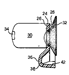
Fig. 4 is a cross-sectional view taken along line 4-4 of Fig.
3; and
Fig. 5 is a rear elevational view of the wall mount.
A cleaning product of the present invention will include a
fluid cleaning composition, a dispenser 2 and a wall mount 4.
Fig. 1 best illustrates the packaging system.
As best seen from Fig. 2, the dispenser 2 includes a front
wall 6, a rear wall 8, a closed end wall 10, a dispensing end
wall 12 opposite the closed end wall 10, and a pair of side
walls 14. Dispenser 2 delivers a liquid or semi-liquid (e.g.
gel) cleaning composition via bottom delivery through a
dispensing opening 16 (with appropriate valve) in cap 18.
Along each of the side walls 14, unitarily formed thereinto,
is a recess 20.
This recess is generally concave and positioned more distant
from the dispensing end wall 12 than from the closed end wall
10 .
Figures 3-5 illustrate the wall mount 4 which functions to
receive and hold the dispenser. Wall mount 4 includes a ~-
shaped bracket 22. The bracket is constituted o~ a back
plate 24 with front and rear surfaces 26, 28 respectively,
left and right arms 30 and a suction cup 32. Left and right
arms 30 parallel one another, each projecting perpendicularly
from the front surface 26 of the back plate 24 and are
structured to form-fittingly couple with recess 20. Suction

WO96~Jl7~ 2 i ~ P~l/~r. '~77l0 ~
cup 32 is joined to the rear surface 2~ of the back plate 24.
The suction cup functions to attach the wall mount to a wall.
Another aspect of bracket 22 are retaining tabs 34 on each of
the arms projecting perpendicularly away from their
respective arm and are oriented toward one another. A
support chin 36 is present ~.o stabilize the dispenser when
held within the bracket. Support chin 36 protrudes outwardly
from the back plate 2~ from its front surface 26 near a lower
edge 38 thereof.
At least a major portion of each of the arms 3~ is contoured
to present an elongated convex surface. The convex surfaces
from each of the arms are facingly juxtaposed ~o one another.
A pair of windows 40 are formed in bac~ plate 14. Each of
these windows ~0 sit astride a respective one of the arms 30.
These windows ~nction as manufacturing aids in the molding
process that produces wall mount 4. In this connection, all
parts of the wa~l mount, except for the suction cup are
unitarily molded to achieve a unitary construction.
A rear support 42 projects perpendicularly outward ~rom the
rear surface 28 of the back plate 24. Figure 5 best
illustrates this feature. ~n the preferred em~diment, the
rear support 42 is a curved ridge oriented along a lower edge
44 of the rear surface of the back plate.
Fluid cleaning compositions of the present invention are
intended to be f l~tion~ mainly for use as shampoos,
conditioners, soaps and detergents. These compositions
generally will contain from 0.1 to 60% of a surfactant.
Typical surfactants may be selected from the group consisting
of anionic, nonionic, cationic, amphoteric and mixtures of
these surfactan~s. ~ater in amounts ranging from 1 to 99~ by
weight usually is also present in the compositions.

~ W096l0~17~ ~l 9 ~ 3 PcT~n5l0~7l~)
Illustrative of shower gels are compositiona comprising 10-
70% water, 1-30~ surfactant ~e.g. cocoyl isethionate,
cocoamidobetaine and sodium lauryl sulfate mixtures), 0.1-10%
humectant (e.g. glycerin~, 0.1-10% silicone oils ~e.g.
cyclomethicone and dimethicone), and minor amounts of
adjuncts such as preservatives (e.g. butylated hydroxytoluene
and Glydant), fragrance, pearescent agents le.g. titanium
dioxide coated mica), deodorants ~e.g. trichlosan),
conditioners (e.g. cationic guar gum~ and viscosity modifying
inorganic salts.
The foregoing description illustrates only selected
embodiments of the present invention, variations and
modifications all being within the spirit and purview of this
invention.

Representative Drawing
A single figure which represents the drawing illustrating the invention.
Administrative Status

2024-08-01:As part of the Next Generation Patents (NGP) transition, the Canadian Patents Database (CPD) now contains a more detailed Event History, which replicates the Event Log of our new back-office solution.

Please note that "Inactive:" events refers to events no longer in use in our new back-office solution.

For a clearer understanding of the status of the application/patent presented on this page, the site Disclaimer , as well as the definitions for Patent , Event History , Maintenance Fee  and Payment History  should be consulted.

Event History

Description Date
Application Not Reinstated by Deadline 2004-07-08
Time Limit for Reversal Expired 2004-07-08
Deemed Abandoned - Failure to Respond to Maintenance Fee Notice 2003-07-08
Inactive: Status info is complete as of Log entry date 2002-05-29
Inactive: Application prosecuted on TS as of Log entry date 2002-05-29
Letter Sent 2002-05-29
Request for Examination Requirements Determined Compliant 2002-05-07
All Requirements for Examination Determined Compliant 2002-05-07
Letter Sent 1997-07-30
Application Published (Open to Public Inspection) 1996-02-15

Abandonment History

Abandonment Date Reason Reinstatement Date
2003-07-08

Maintenance Fee

The last payment was received on 2002-06-26

Note : If the full payment has not been received on or before the date indicated, a further fee may be required which may be one of the following

  • the reinstatement fee;
  • the late payment fee; or
  • additional fee to reverse deemed expiry.

Please refer to the CIPO Patent Fees web page to see all current fee amounts.

Fee History

Fee Type Anniversary Year Due Date Paid Date
Registration of a document 1997-05-29
MF (application, 3rd anniv.) - standard 03 1998-07-08 1998-06-15
MF (application, 4th anniv.) - standard 04 1999-07-08 1999-06-16
MF (application, 5th anniv.) - standard 05 2000-07-10 2000-06-16
MF (application, 6th anniv.) - standard 06 2001-07-09 2001-06-18
Request for examination - standard 2002-05-07
MF (application, 7th anniv.) - standard 07 2002-07-08 2002-06-26
Owners on Record

Note: Records showing the ownership history in alphabetical order.

Current Owners on Record
UNILEVER PLC
Past Owners on Record
JAVIER JR. VERDURA
MARK DZIERSK
MARK JOHN IAIA
Past Owners that do not appear in the "Owners on Record" listing will appear in other documentation within the application.
Documents

To view selected files, please enter reCAPTCHA code :


To view images, click a link in the Document Description column. To download the documents, select one or more checkboxes in the first column and then click the "Download Selected in PDF format (Zip Archive)" or the "Download Selected as Single PDF" button.

List of published and non-published patent-specific documents on the CPD .

If you have any difficulty accessing content, you can call the Client Service Centre at 1-866-997-1936 or send them an e-mail at CIPO Client Service Centre.


Document
Description 
Date
(yyyy-mm-dd) 
Number of pages   Size of Image (KB) 
Representative drawing 1997-06-11 1 5
Description 1995-07-08 7 273
Cover Page 1995-07-08 1 17
Drawings 1995-07-08 2 29
Abstract 1995-07-08 1 57
Claims 1995-07-08 5 141
Cover Page 1998-06-04 1 17
Courtesy - Certificate of registration (related document(s)) 1997-07-30 1 118
Reminder - Request for Examination 2002-03-11 1 119
Acknowledgement of Request for Examination 2002-05-29 1 179
Courtesy - Abandonment Letter (Maintenance Fee) 2003-08-05 1 176
PCT 1997-01-31 9 414
Correspondence 1997-03-04 1 40
Fees 1997-01-31 1 60