Note: Descriptions are shown in the official language in which they were submitted.
WO 96104176 21 G 6 6 9 7 PCT~S95/D9753
- 1 -
HINGED CONTAINER WITH TRANSPARENT AREA
Fiald of the Invention
The present invention relates a container for the
storage of an object. More particularly, it relates to a
container for a,medicament.
8ackaround of the Inveatioa
Containers useful for storing or containing solid
medicaments to be used in the home or at a stationary location
typically include either a cardboard container or a plastic
bottle. For convenience purposes, however, it is preferred
that some medicaments, particularly over-the-counter
medicaments such as cold remedies, pain relievers, vitamins
and the like, be stored in containers which are easily -
portable in the user's pocket or purse. When the user of such
a medicament carries the container in his or her pocket or
purse, however, the container is subjected to an increased
risk of damage from impact and to increased stress from
frequent use and manipulation both of which act to break the
container or more easily force the container open subjecting
the contents of the container to contamination or loss.
Portable containers, such as a metal box used for
throat lozenges, are known in the art. .However, many prior
art containers open too easily under the stresses of portable
use due to weak materials of construction or insufficient
closure mechanisms. Other portable prior art containers have
the_opposite problem, namely, they are difficult to open,
particularly for the elderly or those with conditions which
adversely affect manual dexterity. Attempts to improve the
closures of some of the prior art containers, such as by use
of safety cap features make it overly difficult for the user
of a typical over-the-counter or prescription medicament to
open the portable container. In addition, most portable
WO 96104176 PCT/US95109753
2~9669~
- 2 -
containers do not allow the user of the medicament to view the
contents of the container without opening the container.
Therefore, there is a need in the art for a portable
medicament container which is of a size that easily fits
within a pocket or purse, and which sufficiently withstands
the increased risk of damage and~stress derived from portable
use without inadvertently opening, but which remains easy to
open upon application of manual force by the user. Further, a
need exists for such a container which also includes a feature
wherein the contents of the container may be easily viewed
through a portion of the container without requiring the user
to open the container.
The present invention provides a portable medicament
container having an improved positive closure strong enough to
withstand the stress of portable use, but which is easily
opened by the user. In addition, the present invention
provides such a portable container which also includes a
transparent area which allows the user to view a portion of
the contents of the container without opening the container.
summary of t3xe Invention
The present invention includes a container for
storing and displaying an object. The container comprises a
first base member, a second base member and a hinge. The
first base member has an exterior surface, an interior
surface, a peripheral edge and a transparent area. The
transparent area is located such that an object to be placed
within the container is visible through the transparent area
when the container is in the closed position. The second base
member has an exterior surface, an interior surface, and a
peripheral edge. The hinge interconnects the first and second
base members such that the first base member is movable with
respect to the second base member between a closed position
and an open position. The closed position defines a hollow
interior space for receiving an object to be placed therein.
In the closed position, the peripheral edges of the first and
R'O 96104176 219 6 6 9 l PCTIUS95109753
- 3
second base members are coupled. The open position comprises
a position wherein the first and secon8 base members are
uncoupled except at the hinge and are at least partially
spaced from each other. The first and second base members are
releasably latchable in the closed position.
In an alternative embodiment, the invention includes
a container for storing an object. The container comprises a
first base member, a second base member and a hinge. The
first base member has an exterior surface, an interior surface
and a peripheral edge.' The peripheral edge of the first base
member comprises an exterior flange which is coextensive with
the exterior surface of the first base member and extends from
the peripheral edge of the first base member. The second base
member has an exterior surface, an interior surface and a
peripheral edge. The peripheral edge of the second base
member comprises an interior flange which is coextensive, with
the interior surface of the second base member and extends
from the peripheral edge of the second base member. The hinge
interconnects the first and second base members such that the
first base member is movable with respect to the second bdse
member between a closed position and an open position. The
closed position defines a hollow interior space for receiving
an object to be placed therein. In the closed position, the
exterior flange and the interior flange overlap. The open
position defines a position wherein the first and second base
members are uncoupled except at the hinge and are at least
partially spaced from each other. The first and second base
members are releasably latchable in the closed position.
8 ief Description of the Drawi~aas
The foregoing summary, as well as the following
detailed description of preferred embodiments of the
invention, will be better understood when read in conjunction
with the appended drawings. For the purpose of illustrating
the invention, there is shown in the drawings embodiments
which are presently preferred. It should be understood,
WO 96/04176 PCT/I1S95109753
2i°6697
- 4 -
however, that the invention is not limited to the precise
arrangements and instrumentalitiea shown. In the drawings,
like numerals are used to indicate like elements throughout'
the several views.
Fig. 1 is a perspective, view, partially broken away,
of a container according to the present invention in the
closed position;
Fig. 2 is a perspective view of a container of
according to the present invention in the open position;
Fig. 3 is ari enlarged, partial cross-sectional view
taken along line 3-3 of Fig. 1;
Fig. 4 is an enlarged, partial cross-sectional view
taken along line 4-4 of Fig. 2;
Fig. 5 is a view, partly in front elevation and
partly in cross-section, takes along line 5-5 of Fig. 2;
Fig. 6 is a cross-sectional view taken along line 6-
6 of Fig. 5; and
Fig. 7 is a front elevational view of the container
in the open position taken along line 7-7 of Fig. 2.
Fig. S is a partial cross-sectional view taken along
line 8-s of Fig. 7.
Fig. 9 is partial cross-sectional view taken along
line 9-9 of Fig. 1.
s, a r '"rion of the Prefarsed Embodiments
Certain terminology is used in the following
description for convenience only and is not limiting. The
words "right," "left," "lower" and "upper" designate
directions in orientation of Figs. 1 and 2 of the drawings to
which reference is made. The words "inwardly" and "outwardly"
refer to directions toward and away from, respectively, for
example, the geometric center of the container and parts
thereof. The terminology includes the words above
specifically mentioned, derivatives thereof, and words of
similar import.
WO 96/04176 PCTIUS95109753
2196697
-5-
Referring now to the drawings in detail, there is
shown in Figs. 1-9, preferred embodiments of a container,
generally designated as 10, according to the present
invention.
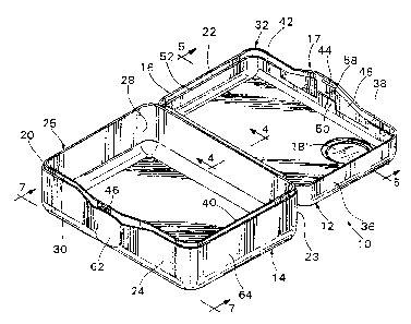
The container 10 includes a first base member 12, a
second base member 14 and a hinge 16. The first base member
includes a transparent area 18. While the drawings show the
first base member 12 as a top lid for the container 10 and the
second base member 14 as a bottom for the container 10, it
should be understood, based upon this disclosure, that the
first and second base members 12, 14 may be reversed without
departing from the scope of the invention. The container l0
in its closed position, as shown in Fig. 1, may have any of a
variety of geometric configurations in plan view, including,
square, rectangular, circular, hexagonal, triangular, ovoid
and the like.- Preferably, the container 1D has an overall
generally square or generally rectangular parallelepiped
configuration in which the container has six adjoining
surfaces at generally right angles to one another, preferably
with rounded adjoining edges and corners as shown. More
preferably, the container 10 is generally rectangular on each
surf ace .
The first base member 12, second base member l4 and
hinge 16 may be made of any suitable packaging material
including metal, plastic, cardboard and similar materials.
However, preferably the first base member 12, the second base
member 14 and the hinge 16 are made of a moldable
thermoplastic or thermosetting polymeric material including,
for example, polyolefin, polystyrene, polyvinyl chloride,
poIyacrylate, polylacetate and copolymers, mixtures and blends
thereof. More preferably, the first base member 12, the
second base member 14 and the hinge 16 are made of a
recyclable thermoplastic material such as a polyolefin, for
example, polypropylene or polyethylene.' The presently
preferred material is polypropylene.
WO 96104176 Q PCT/U595109753
- 6 -
Preferably, the first and second base members 12, 14
are opaque, except for the transparent area 18. Opacity may
be provided in any suitable manner, including using opaque
materials, or incorporating a suitable dye or pigment in the
plastic material forming the container. It is presently
preferred to blend a titanium dioxide white pigment in the
plastic material. Of course, other types and carriers for
pigments or dyes and other colors may be used.
The transparent area 18, is preferably a transparent
member 18' which is separate from the first and second base
members 12, 14 and secured to an area 18 such as the open
transparent area 18 in the first base member 12. The
transparent area 18 is located such that an object, such as
object 19 shown in Fig. 1, to be placed within the container
is visible through the transparent area 18 when the container
is in the closed position. Preferably, only one object 19 is
visible through the transparent member 7:8' which is preferably
sized and shaped in a configuration substantially similar to
the object 19, although the transparent member 18' may be of
such size and shape that more than one object is visible
therethrough, if desired. The transparent member 18', or
window, is preferably also made of a moldable, transparent
thermoplastic material. "Transparent" as used herein, also
includes the term "translucent". It is preferred, however,
that the material is sufficiently light transmissive such that
someone viewing an object through the transparent member 18'
may discern the nature of the object 19. The transparent
member 18' is preferably also colorless, however, a color may
also be provided to the transparent member 18' by coating,
mixing, or blending the material forming the transparent
member 18' with a dye and/or pigment by any suitable method.
More preferably, the window 18' is made of a moldable,
recyclable polyolefin such as, for example, homopolymers and
copolymers of polypropylene and polyethylene. The presently
preferred material for the window 18' is clarified
polypropylene.
0 96104176 PCTIUS95109753
The transparent member 18' may be secured to the
open transparent area 18 by any suitable method. Preferably,
the transparent member 18' is spin welded to the first base
member 12. Alternatively, the transparent member 18' is
preferably insert molded into the first base member 12. The
transparent member 18' may also be formed to be integral with
the first base member 12, such as by co-molding techniques.
It will be-understood, from this disclosure, that other
suitable methods may also be used to secure the transparent
member 18' to the first base member 12 including, for example,
heat- or pressure-sensitive adhesives. '
The transparent member 18' and the open area 18 are
preferably configured within the first base member such that
the transparent member is seated within the area 18. As shown
in Fig. 3, the transparent area 18 may be molded to include an
edge 18a configured to engage a corresponding edge 18a' on the
transparent member 18'. The edges 18a, '18a' are then secured
together as described above.
As shown in Figs. 1 and 2, the first base member 12
and the second base member 14 are configured such that when
the container 10 is in the closed position, the peripheral
edge 22 of the first base member 12 and the peripheral edge 20
of the second base member 14 are coupled. In addition, in the
closed position, a hollow interior apace 21 is defined for
receiving an object, and, preferably, a number of objects,
such as object 19 shown in Fig. 1.
The hinge 16 interconnects the peripheral edge 22 of
the first base member 12 and the peripheral edge 20 of the
second base member 14 such that the second base member 14 is
movable with respect to the first base member 12 between a
closed position as shown in Fig. 1 and an open position as
shown in Fig. 2. In the open position, the first and second
base members 12, 14 are uncoupled except at the hinge 16 sad
are at least partially spaced from each other.
The hinge 16 may be of any suitable type and may
interconnect the first and second base members 12, 14 at any
WO 96!04176 2 j q ~ J 9 7 PCT/US95/09753
_ g _
position along their respective peripheral edges 22, 20. In a
preferably generally rectangular container 10 as shown in
Figs. 1 and 2, the hinge 18 is preferably located on the side
23 of the container 10 opposite the aide 24 of container 10
which includes any suitable latching assembly, such as that
described below.
Preferably, the container 10 is molded as a single
integral piece which includes the first and second base
members 12, 14 and the hinge 16, in which case the hinge 16
and the first and second base members 12, 14 are all
integrally formed of the same material:' It will be
understood, based on this disclosure, that the hinge 16 may be
formed separately of either the same or a different material
than the first base member 12 or the second base member 14
without departing from the scope of the invention. When the
hinge 16 is molded as integral with the first and second base
members i2-, 14, the hinge 16 preferably'has a thickness as
measured in a plane perpendicular to the longitudinal plane of
the hinge 16 which is thinner than the thickness of the first
and second base members 12, 14 as measured transversely across
the peripheral edges 22, 20 of those members 12, 14. The
hinge 16 is preferably thinner to provide flexibility over the
length of the hinge 16. As shown in Fig. 2, the length of the
hinge 16, as measured along the longitudinal axis of the hinge
16, is preferably less than the length of the container 10 as
measured in the same direction in order to prevent portions of
the hinge 16 from extending beyond the length of the container
10 such that the hinge 16 will not catch on objects or be
otherwise damaged. In the open position, the hinge 16 beads
such that a space 17 remains between the first and second base
members as shown in Figs. 4.
The peripheral edge 20 of the first base member 12
and the peripheral edge 22 of the second base member 14 are
releasably latchable in the closed position. A latch assembly
17 releasably latches the peripheral edges 20, 22 of the first
and second base members 12, 14, such that when objects 19 are
O 9fi/04176 219 6 6 9 7 PCTIUS95109753
_ g _
stored within the container 10, the objects 19 may be secured
within the container 10. Other suitable latching arrangements
may be used, in view of the present disclosure, including, for
example, providing the first or second base members 12, 14
with interlocking portions, a snap-fit device, a latch, a hook
and similar latching or locking devices. Preferably the
peripheral edges 20, 24 are releasably latchable by including
A
interlocking flanges and a snap-fit structure as described
below which may be incorporated in the molded structure of the
first and second base members 12, 14.
Preferably, the peripheral edge 20 of the second
base member 14 includes an interior flange 25 which extends
from the peripheral edge 20 of the second base member 14. The
interior flange 25 is preferably molded as part of the second
base member 14 such that the interior surface 26 of the
interior flange 25 is coextensive with the interior surface 28
of the second base member 14. The exterior surface 30 of the
interior flange 25 preferably lies in a plane perpendicular to
peripheral edge 20 of the second base member 14. In addition,
it is preferred that the interior flange 25 extend around the
entire periphery of the second base member 14 as shown in
Fig. 2. r
If the peripheral edge 20 of the second base member
14 includes an interior flange 25, it is also preferred that
the peripheral edge 22 of the first base member 12 includes an
exterior flange 32 which preferably is configured such that
when the container 10 is in the closed position, the interior
flange 25 and exterior flange 32 fit securely together and
overlap as shown in Fig. 9. The exterior flange 32 is
preferably molded as part of the first base member 12 such
that the exterior surface 34 of the exterior flange 32 is
coextensive with the exterior surface 36 of the first base
member 12. Preferably, the interior surface 38 of the
exterior flange 32 lies in a plane perpendicular to the
peripheral edge 22 of the first base member 12. The exterior
flange 32, like the interior flange 25, preferably extends
WO 96104176 PCTIUS95109753
- 10 -
around the entire periphery of the first base member 12 as
shown in Fig. 2. The interior flange 25 and exterior flange"
32 together operate to help the container 10 to be more
securely releasably latchable in the closed position.
The exterior and interipr flanges 25, 32 are
preferably configured such that when the container 10 is in
the closed position,,the flanges 25, 32 overlap. To ensure a
secure overlap between the exterior flange 32 and the interior
flange 25 when the container l0 is closed, the height of the
interior flange 25 as measured transversely from the
peripheral edge 20 of the second base member 14 to the edge 40
of the interior flange 25 is preferably substantially the same
as the height of the exterior flange 32 as measured
transversely from the peripheral edge 22 of the first base
member 12 to the edge 42 of the exterior flange 32.
While the drawings show the exterior flange 32~
located on the first base member i2 and the interior flange 25
located on the second base member 14, the interior and
exterior flanges 25, 32 may be on either of the base members
12, 14 without departing from the scope of the present
invention.
The interior flange 25 and exterior flange 32 are
preferably made to snap-fit together by.including a projection
44 and a notch 46 each located on one of either of the
interior or the exterior flanges 25, 32. While the drawings
show that the projection 44 is located on the interior surface
38 of the exterior flange 32 on the first base member and the
notch is located on the exterior surface 30 of the interior
flange 25 on the second base member, the opposite orientation
would be equally effective. The notch 46 is preferably
configured to receive the projection 44 when the container 10
is in the closed position. As such, the notch 46 and the
projection 44 should be located such that they are aligned
with one another on the flanges 25, 32. The notch 46 and the
projection 44 may have any configuration in elevation view
including circular, square, rectangular, triangular and the
WO 96104176 PCT/US95109753
~ 2196~R~
- 11 -
like. Preferably, as shown in Figs. 2 and 5-9, the projection
44 has a raised generally rectangular shape. The notch 46 as
shown in Figs. 2 and 5-9 preferably has a recessed rectangular
_ shape. The notch 46 and projection 44 are preferably molded
as part of the corresponding first or second base member 12,
14 on which they are located, however, they may be separate
pieces attached by an adhesive or by other similar methods.
The latching ability of the flanges 25, 32 may also
be enhanced by including at least one planar member 48
disposed inwardly from at least a portion 50 of the interior
surface 52 of the first base member. The longitudinal plane
of the planar member 48 is also preferably generally parallel
to at least a portion 50 of the interior surface 52 of the
first base member 12 which is part of the side 24 of the
container 10 opposite the hinge 16 as shown in Fig. 6.
Generally parallel in this instance includes a slight angle of
incline between the planar member 48 and the portion 50 of the
interior surface 52 of the first base member 12 of about 10°.
The planar member 48 may have any suitable shape.
As shown in Figs. 2 and 5, the planar member is preferably
configured such that it complements the configuration of the
exterior flange 32. As shown in Figs. 2 and 5, the planar
member 48 has a curved outline which closely corresponds to
the curved outline of the exterior flange 32 proximate the
latching assembly 17. Preferably, there are more than one
coextensive planar members 48, as shown in Figs. 2 and 5 and
the planar members 48 are molded as an integral part of the
first base member 12. As shown in Fig. 6, the planar members
48 are disposed inwardly within the container 10 such that a
channel 54 is formed between each of the planar members 4s and
the interior surface 38 of the exterior flange 32 for
receiving the interior flange 25 when the container 10 is in
the closed position. The channel 54 is preferably of a
thickness as measured between the interior surface 38 of the
exterior flange 32 and the exterior surface 56 of the planar
members 48 which corresponds roughly to.the thickness of the
WO 96/04176 L ~ l ~ b 9 7 PCT/US95109753
- 12 -
interior flange as measured transversely across the edge 40 of
the interior flange 25. The channel 54 preferably also has a
depth which corresponds to the height of the interior flange
25. _
The planar members 48 function to more securely
latch together the base members 12, 14 by providing additional
positive support to the overlapping flanges 25, 32 when
placing the container 10 in the closed position. The planar
members 48 also aid in holding the interior flange 25 in place
against the exterior flange 32 When the container 10 is
closed. In addition, if a projection 44 and notch 46 are used
in conjunction with the planar members 48, the planar members
48 help to smoothly and accurately guude the interior flange
25 into the channel 54 such that the projection 44 and the
notch 46 easily snap together when closing the container 10.
Once closed, the planar members help to support the projection
44 and notch 46 in their latched position to prevent the
container 10 from-opening too easily.
The projection 44 and the notch 46 are preferably
2,,0 located in a space 58 between two planar members 48 such that
each planar member 48 stabilizes and supports the notch 46 and
projection 44 from either side. As shown in Fig. 6, if the
notch 46 and projection 44 are used in conjunction with the
planar members 48, the exterior surfaces 56 of the planar
members 48 are preferably also slightly inclined such that
edge 40 of the interior flange 25 is more easily guided past
the projection 44 into the channel 54.
The container 10 in the closed position, may be made
easier to open by making a portion 60 of the exterior surface
36 of the first base member 12 and a portion 62 of the
exterior surface 64 of the second base member 14 textured as ,
shown in Figs. 1, 2 and 7. it will be understood, based on
this disclosure, that the texturing of any portion of the
exterior surface of either base member 12, 14 would also
facilitate opening of the container 10.
O 96104176 2 ~ ~, ~ ~ ~ ~ PCTIUS95109753
- 13 -
As an alternative, or preferably in addition to
providing a textured exterior surface portion to one or both
of the base members, a portion 66 of the exterior surface 36,
64 of one of the first or second base members 12, 14 may be
- 5 recessed inwardly such that a portion 68 of the peripheral
edge of the non-recessed exterior surface of the other base
member extends relatively outwardly compared to the recessed
portion 66 providing an overhang 68. The overhang facilitates
opening of the container. As shown in Figs. 1, 2, 7 and 9,
the textured portion 62 of the second base member 14 is
recessed to create a recessed portion or depression 66 in the
exterior surface 64 of the second base member 14. A
corresponding textured portion 60 of the exterior surface 36
of the first base member 12 is not recessed. A portion 68 of
the peripheral edge 22 of the first base member 12 extends
outwardly beyond the peripheral edge 20 of the recessed
textured portion 62 of the exterior surface 64 of the second
base member 14 in the area of the depression 66. The extended
peripheral edge portion 68 facilitates opening of the
container 10 by providing a location for the application of
manual force to open the container. It will be understood,
based upon this disclosure, that the recessed portion 66 may
be on either of the first or second b~lse members 12, 14 and
that there may be more than one recessed portion without
departing from the spirit of the present invention.
In an alternative embodiment, the container 10 may
be made for storing an object, such as object 19 shown in Fig.
1. In this embodiment, the container 10 includes a first base
member 12 having a peripheral edge 22 which includes an
exterior flange 32 as described above, a second base member 14
having a peripheral edge 20 which includes an interior flange
25 as described above and a hinge 16. In this embodiment, the
. first base member 12 may not include a transparent area 18.
However, it is preferred that a transparent area 18 or
transparent member 18' as described above be provided to the
container 10 such that objects stored within the container are
W O 96/04176 ~j' PCTIUS95/09753
- 14 -
visible through the container l0. In this embodiment, the
first and second base members 12, 14 are interchangeable and
may be made from any of the materials and in any of the
configurations as described above. In the closed position,
the flanges 25, 32 overlap.
The objects 19 to be stored in either embodiment of
the container 10 of the present invention are preferably
medicaments, although many other objects, such as, for
example, and without limitation, vitamins, candy and other
food items, cosmetics, jewelry, childrens' toys, coins and the
like, may also be stored and/or displayed in the container 10.
Typical preferred medicaments for storage and/or display in
the container 10 may be in the form of a tablet, caplet,
capsule, or lozenge. Preferably, the medicament is a lozenge
or antacid. Such medicaments are preferably also safety
sealed in an airtight package within the container, such, as,
for example, the blister packaging 70 shown in Fig. 1. The
blister package 70 preferably includes a transparent or at
least translucent covering portion such that each individual
medicament is visible through the packaging.
It is particularly preferred that the medicaments or
objects 19 and any internal packaging are positioned within
the container 10 such that the transparent area 18, or
transparent member-18', which is preferably configured to be
of substantially the same general shape.and size of the object
19 is aligned with the object I9 to display the object 19. In
this manner, consumers or users of the container 10 may view
at least a portion of its contents by looking through the
transparent area 18.
Other optional features which may be included on a
container 10 made in accordance with the present invention ,
include a recessed portion 72 of either of the exterior
surfaces 36, 64 of the first or second'base member 12, 14
which may be used to offset any labelling provided or for
other aesthetic purposes. In addition, the flanges 25, 32 and
peripheral edges 20, 22 of the first and second base members
R'O 96104176 ~ PCTlUS95109753
~ L1 °061
- 15 -
12, 14 may be provided with varying outline configurations to
facilitate opening of the container 10, ~to improve upon the
overall appearance of the container 10~ and/or to draw '
attention to the latching assembly for the container 10. For
example, as shown in Figs. 1, 2, 5 and 7, the exterior flange
32 and the peripheral edge 22 of~the first base member 12 are
configured to curve downwardly over the portion of the first
base member proximate the latching means. In Fig. 1, the
curvature is centered approximately around the textured
portion 60 of the first base member 12. The interior flange
25 and the peripheral edge 20 of the second base member 14 are
also curved downwardly to provide a corresponding shape to the
second base member in the area proximate the textured portion
62 of the second base member 14. The curvature provided to
the flanges 25, 32 and base members 12, 14 functions to draw
the attention of the user toward the latching assembly of the
container 10 and also provides additional surface area for the
inclusion of components of the latching assembly shown,
including planar members 48, projection 44 and notch 46.
The container 10 may also be molded to include such
features and indicia (not shown) as product marking,
instructions for use of any enclosed medicaments,
manufacturers' information or the recyclable nature, if any,
of the base components of the container 10. Further safety
packaging (not shown), such as a shrink wrap or similar film
may be provided around the exterior of the container 10 to
protect the objects 19 from tampering or aging.
It will be appreciated by those skilled in the art
that changes could be made to the embodiments described above
without departing from the broad inventive concept thereof.
It is understood, therefore, that this invention is not
limited to the particular embodiments disclosed, but it is
intended to cover modifications within the spirit and scope of
the present invention as defined by the appended claims.