Note: Descriptions are shown in the official language in which they were submitted.
- 2196730
-2-
Title: Display Rack
FIELD OF THE INVENTION
This invention relates to display racks, and more
particularly is concerned with display racks for displaying merchandise
for sale at a retail level.
BACKGROUND OF THE INVENTION
There are many goods which are packages in relatively
small quantities and which are intended for sale individually at the
retail level. This raises various problems, such as: displaying the goods
in a manner which keeps the goods protected and arranged; displayin g
the goods in a manner which is attractive to potential customers;
enabling customers to have ready access to individual items of the
goods; enabling containers holding individual packages to be readily
replaced with full containers.
At least some of these problems, individually, have been
recognised in the art. Thus, the following U.S. design and utility
patents disclose display racks or the like:
D 114,997 E. E. Humphries
D 133,723 E. P. May
D 186,254 Georges Tirlet
D 189,900 Marcel M. Arnould
D 206,737 Roy C. Brown
D 287,912 Pietro Ferrero
D 295,931 George A. Bezzerides
D 369,037 Philip D. Wyatt
D 284,049 Nathan et al.
2,495,109 F. Kramer
4,363,496 Charles P. Schreiner
4,387,810 Louis J. Crosslen
2196730
-3-
4,586,618 Timothy H. Norman
4,726,477 Larry Martin
5,582,302 Ira M. Kozak
Many of these proposals show some common elements.
Thus, the Humphries, May, Tirlet and Arnould patents, and others
show the basic concept of narrow tiers or shelves stacked vertically, to
display goods to a potential customer. Many of the design patents also
show similar features. Of interest, some patents, such as the Wyatt, and
Nathan et al. patents show inclined shelving, so as to present better
access to the goods, and possibly to encourage goods to slide down to the
front of the shelves, when the shelves are only partly full. In such
cases, it is common to provide a front ledge or lip to the shelf, to hold
the goods in place.
A number of the utility patents address the issue of
attaching containers to carts, frames and the like. Thus, the Schreiner
patent shows a material handling cart with individual totes which rely
on their own weight and the effects of gravity to retain them in
position. They are retained by downwardly extending flanges that
engage a crossbar or support rail. Similarly, in the Crosslen patent,
merchandising support racks are held on a point of purchase display
providing a so-called shingled effect. The racks are provided with an
arrangement to engage traverse bars, so that they can hang and pivot. It
is particularly concerned with displaying cigarette packages.
The Norman patent again relies on gravity and a flange
arrangement to retain containers in position.
A common characteristic of known display racks is that it
is assumed that the goods or merchandise must be completely
supported underneath, and further where a sloping shelf is provided
that some sort of edge or lip must be provided at a front, lower edge, to
retain a product on the shelf or rack. Consequently, in such designs, it is
common to provide some sort of side frame or gable supporting the
CA 02196730 2004-10-29
-4-
individual shelves or racks. Even if this is in the form of an open wire
frame or the like, the overall effect is to enclose the product or
merchandise on all sides, except for the front. In many cases, the display
is then riot very appealing, and a product is not that readily accessible to
a consumer. Moreover, where a product comes in containers for
display, the containers are often carefully designed with advertising
information and the like on their exterior, which is often frequently
hidden, or partially hidden by the framework of the display stand.
SUMM~.RY OF THE INVENTION
Accordingly, the present inventors have realised that what
is desirable is to display a product in a manner which gives the
appearance of being freestanding or floating, and which gives the sense
that a container holding the product is unattached. They have realized
that if this can be achieved, numerous advantages flow. The overall
display is then more open making the product more accessible to a
potential purchaser. Where containers are employed for holding the
product, advertising and like material inside of the containers is then
fully exposed and not in any way obstructed, making the display more
attractive.
Accordingly, what is required is a display rack, or point of
purchase display, which is simply robust, provides effective display of
the goods, enables containers for the goods to be quickly and simply
exchanged.
In accordance with one aspect of the present invention,
there is provided a free standing display rack comprising: a supporting
framework having a base portion for supporting the display rack on a
substantially horizontal surface; and at least one container support
integrally secured to the supporting framework and including a bottom
portion, for supporting a container, and a downwardly-facing
engagement means adapted to engage a rear wall of the container,
whereby, in use, a container including a bottom wall and a rear wall is
' CA 02196730 2005-09-09
-4a-
supported on the container support bottom portion and the rearwall engages
the engagement means.
The display rack includes a plurality of container supports which
are vertically stacked above one another, and each of which is inclined
forwardly and downwardly. Advantageously, each container support then
comprises a bottom portion, a rear portion extending generally perpendicular
thereto and a flange extending downwardly from the rear portion, the flange
comprising the engagement means.
The supporting framework includes two side frames between
which the container supports are secured. Each side frame includes a plurality
of steps, each of which comprises a generally horizontal portion and an
upwardly extending portion, which steps are substantially continuous with one
another. More preferably, the side frames are secured to the container
supports so as to project above the bottom portions of the container supports
and to provide lateral support for the containers. Conveniently, the side
frames
are formed from an elongate element of substantially constant, circular cross-
section, and the container supports are formed from sheet material.
The present invention also provides in combination, a display
rack as just defined, and a plurality of containers each of which comprises a
bottom wall, side walls, a front wall and a rear wall, with the rear wall of
each
container engaged with the flange of a container support. Each container can
contain a plurality of individual packets of merchandise, for example a
plurality
of packets of mints, chewing gum or other candies. In a preferred embodiment,
the length of each container is longer than an underlying container support,
by
an amount such that the weight of the container maintains its rear wall in
engagement with the engagement means.
In accordance with a second aspect of the present invention,
there is provided a display rack comprising: a supporting framework
comprising a pair of spaced apart side frames; a plurality of
CA 02196730 2004-10-29
-5-
container supports integrally secured to the two side frames, each
container support including a bottom portion, for supporting a
container, and a downwardly-facing engagement means adapted to
engage a rear wall of a container, whereby, in use, a container including
a bottom wall and a rear wall is supported on the container support
bottom portion and the rear wall engages the engagement means.
In accordance with a third aspect of the present invention,
there is provided a display rack comprising: a supporting framework;
and a plurality of container supports integrally secured to the
supporting framework and each including a bottom portion, for
supporting a container, and a downwardly and facing engagement
means adapted to engage a rear wall of the container, whereby in use, a
container including a bottom wall portion and a rear wall portion is
supported on one of the container support bottom portions, with the
rear wall thereof engaging the corresponding engagement means, and
wherein the container supports are vertically stacked above one another
and relatively close to one another, whereby supported containers are
close to one another, and each container support is inclined forwardly
and downwardly, whereby a forward portion of each container projects
out below any container above the first-mentioned container, and
articles within the containers will tend to slide towards the front
thereof, whereby the articles are readily viewed and accessed.
In accordance with a further aspect of the present
invention, there is provided a display rack comprising: a supporting
framework formed from an enlongate element of substantially constant
cross-section and a plurality of container supports secured to the
supporting framework, each container support being formed from sheet
material and including a bottom portion, for supporting a container,
and a downwardly facing engagement means adapted to engage a rear
wall of a container whereby, in use, a container including a bottom wall
and a rear wall is supported on the container support bottom portion
with the rear wall of the container engaging the engagement means.
CA 02196730 2004-10-29
-5a-
For a better understanding of the present invention, and to
show more clearly how it may be carried into effect, reference will now
be made, by example, to the accompanying drawings in which:
2196730
-6-
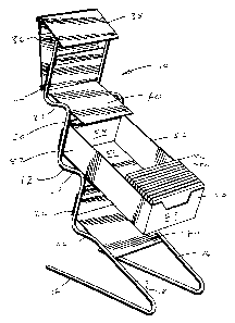
Figure 1 is a perspective view of a display rack and a
container in accordance with the present invention; and
Figure 2 is a side, sectional view of the display rack of
Figure 1, indicating schematically the mounting of a container.
DESCRIPTION OF THE INVENTION
The display rack of the present invention is indicated
generally by the reference 10. The display rack 10 has first and second
side frames 12, 14. Each side frame 12, 14 is formed from coated wire
and has a substantially uniform, circular cross section. The side frames
12, 14 are essentially identical and, for simplicity, are described in
relation to the side frame 12. T'he side frame 12 shows a generally zig
zag or sawtooth profile. The side frame 12 has a base portion 16, and
extending from the forward end of the base portion 16, a rearwardly
extending leg 18, the leg 18 extending rearwardly and upwardly.
Above the leg 18 there are three step or sawtooth portions
20 each of which comprises a horizontal portion 22 and an upwardly
extending portion 24. Each upwardly extending portion 24 extends
slightly forwardly. A cross bar 26, of smaller section than the side
frames 12, 14, joins the frames 12, 14 together near the top.
Extending between the side frames 12, 14 are a number of
elements formed from coated, sheet steel or the like. At the upper end
of the rack, there is a mounting bracket 30 which comprises a vertical
portion 32 and a pair of flanges 34, 35 facing towards one another,
enabling bracket 30 to be slid onto a suitable vertical strip. The vertical
portion 32 is also provided with apertures 36, to enable mounting or
securing of the display rack 10 by means of screws or the like.
An upper attachment member 38 includes a vertical flange
at one end secured, for example by welding, to the mounting bracket 30.
At its forward edge, the sheet material of the upper attachment member
38 is folded back and it is welded or otherwise secured to the crossbar 26.
Now, in accordance with the present invention, to enable
2196730
the product to be displayed and mounted, the display rack 10 includes a
plurality of container supports 40, here three container supports 40,
which are generally identical with one another and which are welded at
their side edges to the side frames 12, 14. Like the mounting bracket 30
and the upper attachment member 38, the container supports 40 are
formed of sheet metal.
Each container support 40 comprises a bottom portion 42, a
rear portion 44 and a downwardly extending flange 46. It can be noted
that an additional angled attachment member 48 is provided between
the mounting bracket 30 and the uppermost container support.
The container supports 40 are dimensioned to receive and
mount containers 50. Here, each container 50 is a cardboard box, which
is generally rectangular and is open at the top. For transportation
purposes, in known manner, the containers 50 can be provided with
upper closures, to pack the goods within them. Again, in known
manner, the closures would be removed before mounting the
containers for display. Alternatively, the containers could be packaged
in a larger, box, which protects them, and eliminates the requirement
for any separate closure.
Each box 50 has side walls 52, a front wall 53, a rear wall 54
and a bottom wall 55. The containers 50 are here shown containing
individual packets of candies, for example mints or the like, indicated
schematically at 56. It will be recognized that any suitable merchandise
can be displayed using the rack of the present invention, and the rack
would then be dimensioned accordingly.
Now, the bottom portions 42 of the container supports 40
have a length "L". The containers 50 in turn have a length indicated at
"M". Here, the length "M" is more than twice the length "L", for
reasons explained below. Additionally, the rear portions 44 of the
supports 40 have a height corresponding to the height of the container
rear walls 54.
In use, as shown in Figure 2, an upper edge of each
219 6730
_g_
container rear wall 44 is engaged under the flange 46. The forward end
of the container 50 is then permitted to swing downwards to bring the
container 50 into abutment with the bottom and rear portions 42, 44.
The effect of the container length "M" being greater than
the length "L" is to ensure, that at all times the centre of gravity of the
container 50 and its contents lies forward of the front edge of the bottom
portions 42. This ensures that the weight of the container 50 keeps its
rear wall 54 into full engagement with the flange 46. Note that when
the container 50 is full, its centre of gravity will be approximately at its
mid-point. As product is purchased, i.e. as individual packets 56 are
removed, the container 50 will be partially full, and at this point, the
product will reside at the forward end of the container 50.
Consequently, the effective load maintaining the rear wall 54 in
engagement with the flange 46 is increased.
This arrangement has a number of advantages. The
structure is relatively simple. Each container 50 is essentially just
supported underneath by the bottom portion 42 and held at the upper
edge of the rear wall 54. It can further be noted that this secures the
container 50, even against disturbance by users removing the packets 56.
A user reaching in for a packet 56 will, if anything, exert a simple
downward load on the container 50.
The flange 46 has a width corresponding to the rear wall
54. Hence, it abuts against the insides of the side walls 52, to resist any
movement tending to dislodge the container 50 sideways. In any event,
the side frames 12, 14 are also dimensioned so as to abut at least partially
against the sides of the container 50 to locate it laterally.
Another reason for having the container length M
sufficiently greater than the length L is to provide sufficient clearance
for the containers to be swung upwards, as shown for the uppermost
container 50 in Figure 2, for mounting and removal of the containers
50. Where this clearance can be provided otherwise, e.g. by greater
vertical spacing or setting the containers further back from one another
219 673
-9-
in an upward direction, or even by locating the container side by side in
a row, then this length ratio is not critical. More importantly, it is not
essential in the present invention for the center of gravity of the
containers 50 to be forward of the container supports 40. Indeed, it is
possible for the bottom portion 42 of each container support 40 to extend
to near the front of a respective container 50.
Then, the weight of the container 50 is essentially taken by
the bottom portion 42 of the container support 40. The flange 46 then
serves to retain the container in position and stop it from sliding down
the container support. This thus provides a clean, unobstructed
support for the containers 50, leaving them open both at the front and
at the sides. A product is then readily available to the consumer, and all
advertising and other information on the sides of the containers 50 are
readily available and not obstructed by any supporting framework.
It will be appreciated that while a preferred embodiment of
the invention has been described, many variations are possible within
the scope of the present invention. Thus, it is not essential for the side
frames to be formed from wire and the other elements to be formed
from sheet metal. The whole rack could be formed from pressed sheet
steel or from wire, or alternatively the entire rack could be moulded
from a plastic material or the like.
It will also be appreciated that the rack 10 is described above
in relation to its normal configuration in use, either standing on a flat,
horizontal surface, or mounted to a vertical wall or the like. The terms
such as "horizontal", "vertical", "rearwardly", "upwardly", etc. should
be construed accordingly.