Note: Descriptions are shown in the official language in which they were submitted.
Title
Adjusting Mechanism
Field of the Invention
The present invention relates to an adjusting mechanism for
adjusting the position of a first structural member relative to a
second structural member. The mechanism is particularly well
suited for use as a mechanism for adjusting the vertical or
lateral position of a chair back or armrest relative to a chair
seat, and specifically to a device which is adapted for one
handed adjustment.
Backctround of the Invention
In office chairs, it is typically necessary to provide a
mechanism which allows the chair user to adjust the vertical or
lateral position of the back of the chair back relative to the
chair seat. Such a mechanism permits the chair user to customize
the chair to accommodate the user's particular size and comfort
choices.
In the past, vertical chair back adjusting mechanisms have .
comprised a slider mounted on a chair back. The slider slidably
engages an arm extending upwards from the chair seat. In order
to lock the chair back in a fixed position, such mechanisms have
further employed a screw assembly extending from the slider. The
screw assembly, is typically operable by a lever, knob or handle.
The screw mechanism, when tightened, causes a friction fit
between the chair back slider and the arm. These known
mechanisms, however, are cumbersome as they require a chair user
to utilize both hands to effectively adjust the chair back.
1
a
Devices allowing one handed vertical adjustment of a chair
back relative to a chair seat are known. For example, U.S.
Patent No. 4,749,230 issued June 7, 1988 and naming Tornero as
inventor discloses a height adjusting device for a chair backrest
employing guided slidably interlocking plates and a locking pin
disposed in a slotted track. This device, however, relies on the
free sliding of the locking pin and the force of gravity on this
pin. Accordingly, as the mechanism becomes dirty and worn it
often fails to operate smoothly.
Similarly, U.S. Patent No. 4,639,039 issued January 27, 1987
and naming Donovan as inventor discloses a height adjustment
mechanism for a chair backrest. This mechanism, while effective,
utilizes numerous parts, including a coiled torsion spring. It
is accordingly somewhat cumbersome to manufacture and assemble.
The present invention attempts to overcome many of the
disadvantages of the known devices.
Summary of the Invention
In accordance with one aspect of the invention, there is
provided a chair back adjusting mechanism, comprising an arm,
mountable to a chair seat to extend therefrom; a slider securable
to a chair back and adjusted to slidably engage said arm; a
ratchet rack on said arm; a pawl supported by said slider adapted
to engage said ratchet rack; one of said slider and said pawl
having a cam guide, said guide having a substantially horizontal
portion extending in a direction substantially transverse to said
rack, and a substantially vertical portion interconnected to said
substantially horizontal portion and extending in a direction
substantially parallel to said rack from said substantially
horizontal portion; the other of said slider and said pawl having
a cam follower extending therefrom, said cam follower slidably
engaging said cam guide; a biasing member, resiliently pushing
2
2~9'~ a2~
said pawl into engagement with said ratchet rack and forcing said
cam follower along said substantially horizontal portion of said
cam slot, away from said substantially vertical portion of said
cam guide; one of said arm and said pawl having a first camming
surface, the other of said arm and said pawl having a first
abutting surface such that when said pawl first surface is pushed
into abutment with said arm first surface said cam follower is
forced along said substantially horizontal cam guide portion and
into said substantially vertical cam guide portion; said pawl
being disengaged from said ratchet rack when said cam follower is
positioned in said substantially vertical portion of said cam
guide said arm having a second surface such that when said pawl
is pushed into abutment with said second surface of said arm said
cam is forced from said substantially vertical portion and into
said substantially horizontal portion of said cam guide.
In accordance with another aspect of the invention, there is
provided an adjusting mechanism for adjusting the position of a
first structural member relative to a second structural member,
comprising an arm, mountable to said first structural member to
extend therefrom; a slider securable to said second structural
member and adapted to slidably engage said arm; a ratchet rack on
said arm; a pawl supported by said slider adapted to engage said
ratchet rack; one of said slider and said pawl having a cam
guide, said guide having a first guide portion extending in a
direction substantially transverse to said rack, and a second
guide portion interconnected to said first guide portion and
extending in a direction substantially parallel to said rack from
said first guide portion; the other of said slider and said pawl
having a cam follower extending therefrom, said cam follower
slidably engaging said cam guide; a biasing member, resiliently
pushing said pawl into engagement with said ratchet rack and
forcing said cam follower along said first guide portion of said
cam slot away from said second guide portion; one of said arm and
said pawl having a first camming surface, the other of said arm
3
217 028
and said pawl having a first abutting surface such that when said
pawl first surface is pushed into abutment with said arm first
surface said cam follower is forced along said first guide
portion and into said second guide portion; said pawl being
disengaged from said ratchet rack when said cam follower is
positioned in said substantially second portion of said cam
guide; said arm having a second surface such that when said pawl
is pushed into abutment with said second surface of said arm said
cam follower is forced from said substantially second guide and
into said first guide portion of said cam guide.
Brief Description of the Drawincrs
In drawings which illustrate a preferred embodiment of the
invention,
Figure 1 is a perspective view of an office chair
incorporating a chair back adjusting mechanism in accordance
with an embodiment of this invention;
Figure 2 is a detailed elevational view of part of the chair
back adjusting mechanism of the chair of figure 1;
Figure 2A is a cut-away view of figure 2;
Figure 2B is a cross-sectional view taken along 2B-2B in
figure 2A;
Figure 2C is an enlarged detailed view of a portion of
figure 2A;
Figure 3 is another detailed elevational view of part of the
chair back adjusting mechanism of the chair of figure 1;
Figure 3A is a cut-away view of figure 3;
4
CA 02197028 2004-07-07
Figure 4 is another detailed elevational view of part
of the chair back adjusting mechanism of the chair of
figure 1;
Figure 4A is a cut-away view of figure 4;
Figure 5 illustrates an office chair incorporating an
adjusting mechanism in accordance with another
embodiment of this invention that is adapted for
adjusting the lateral position of a chair back relative
to a chair seat;
Figure 6 illustrates an office chair incorporating an
adjusting mechanism in accordance with yet another
embodiment of this invention that is adapted for
adjusting the vertical position of a chair armrest
relative to a chair seat.
Detailed Description of the Preferred Embodiment
Figures 1-4A illustrate a first preferred embodiment of
the invention.
Figure 1 illustrates an adjusting mechanism 10, in
accordance with this invention. The mechanism is used as a
chair back adjusting mechanism and forms part of a
conventional office chair 12. The adjusting mechanism 10 has
an arm 38 and slider 40. Arm 38 extends from chair seat 14.
Arm 38 consists of a portion 42 extending vertically upward
from chair seat 14 and a further portion 44 which attends
substantially horizontal and may be attached by way of bolts
or screws to the bottom of chair seat 14. Arm 38 is
typically made of a material such as metal, and is
configured to withstand a typical backward force that might
be applied by a user of the chair while resting against
chair back 16. Slider 40 is attached to chair back 16, and
may be so attached by bolts or screws or other conventional
5
CA 02197028 2004-07-07
fasteners.
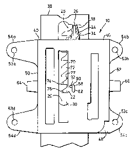
As shown in figures 2, 2A, and 2B, slider 40 comprises
two outer walls 46 and 48. Front outer wall 46 and back
outer wall 48 oppose each other and are spaced from and are
oriented generally parallel to each other. Back outer wall
48 and front wall 46 are interconnected at their side edges
by side walls 50 and 52. All these walls may be made of a
durable material such as a hard plastic or metal and may be
integrally formed. Extending from side walls 50 and 52 are
four flanges 54 having retaining holes 53a-d for fixedly
mounting slider 40 to chair back 16. When mounted on chair
back 16, screws or bolts (not shown) extend through the
retaining holes 53a-d in flanges 54 into chair back 16.
Located within walls 46 and 48 are respectively cam guides
58 which take the form of inverted L-shaped cam slots.
Guides 58 are identical in shape and size and are disposed
opposite each other. Each guide comprises a vertical portion
62 extending parallel to the orientation of a ratchet rack
20 and a horizontal portion 60 extending generally
transverse to ratchet rack 20.
A pair of grips 64 and 66 extend outwardly from
opposite side walls 50 and 52 of edges of slider 40. As
depicted in figure 2B, walls 46, 48, 50 and 52 form a
channel 68 which receives arm 38.
As shown in figure 2A, located within arm 38 is cut-out
18. Mounted within cut-out 18 is ratchet rack 20. Ratchet
rack 20 has a number of teeth 70 and a number of gaps 72
between teeth 70. The ratchet rack 20 is made of similar
material to walls 46 and 48. Ratchet rack 20 is mounted
within cut-out 18 opposite edge 34 of cut-out 18. Ratchet
rack 20 alternatively may be integrally formed as part of
arm 38 by cut-out 18. A pawl 22 rests and is moveable in
cut-out 18 between walls 46 and 48, and is adapted to engage
rack 20. Pawl 22 is similarly made of the same material as
ratchet rack 20 and walls 46 and 48. The thickness of pawl
6
CA 02197028 2004-07-07
22 is approximately equal to the thickness of arm 38.
Pawl 22 has two teeth 74 and 76 for engagement of gaps
72 of rack 20. Pawl 22 further has a camming surface 77. A
leaf-spring 24 is positioned between edge 34 of cut-out 18
and a biasing bar 26. Leaf spring 24 is typically fabricated
of a resilient metal. Biasing bar 26 is deformable along its
length and accordingly is made of a resilient material such
as deformable plastic. It also has a thickness approximately
equal to the thickness of arm 38. A spring force is exerted
by leaf spring 24 on biasing bar 26, causes biasing bar 26
to arc slightly toward ratchet rack 20. As a side of pawl 22
is in abutment with biasing bar 26, this force, in turn,
resiliently pressures pawl 22 into engagement with ratchet
rack 20. Spacers 28 and 30 extend from the top and bottom of
ratchet rack 20, respectively. These spacers 28, 30 space
the ends of biasing bar 26 at a minimum distance from
ratchet rack 20. Spacer 28 additionally has a camming
surface 78, thereby giving pawl 22 freedom of movement.
A cam follower in the form of a retaining pin 32
extends through and is mounted in pawl 22 and engages guides
58 in walls 46 and 48. Retaining pin 32 is typically formed
of steel. The length of retaining pin 32 is slightly longer
than the sum of the widths of walls 46, 48 and arm 38.
Retaining pin 32 may freely slide within guides 58, but
remains stationary relative to pawl 22. A considerable
coefficient of friction exists between the retaining pin 32
and the walls of guides 58.
In operation, an operator sits on a chair such as the
chair shown in figure 1. In order to properly adjust the
height of chair back 16 relative to chair seat 14, chair
back 16 may be pulled in an upwardly direction away from
seat 14. Slider 40 slidably engages arm 38 which guides
slider 40 and is seated within channel 68. As will be
explained below, because of the engagement of slider 40 with
arm 38, chair back 16 may not be slid downward toward chair
7
CA 02197028 2004-07-07
seat 14 until slider 40 is slid to the top of its path along
arm 38.
As shown in Figure 2, beginning with slider 40 in a
locked position, pawl 22 engages ratchet rack 20. In such a
locked position slider 40, which is sealed to chair back 16,
may be pulled upwardly away from chair seat 14.
Conveniently, grips 64 and 66 may be used to pull slider 40.
As the slider 40 is pulled upward, pawl 22 is pulled upward
by retaining pin 32 resting in guides 58. Pawl 22, in turn
moves upwardly and horizontally away from rack 20 as it
passes by a tooth 70 of rack 20. This motion of pawl 22 is
caused by the interaction of pawl 22 and rack 20. During
this motion, retaining pin 32 slides in the horizontal
portion of guides 58 in a direction perpendicular to the
direction of motion of slider 40, and generally away from
ratchet rack 20. As pawl 22 slides in this direction, a
force is exerted on biasing bar 26 toward wall 34, this
force is resisted by a force in the opposite direction,
provided by leaf spring 24. As teeth 74 and 76 of pawl 22
slide past teeth 70 of ratchet rack 22, the force exerted by
leaf spring 24, forces pawl 22 to return into engagement
with rack 20. Specifically, teeth 74 and 76 of pawl 22
engage gaps 72 of rack 20. As illustrated in figure 2C, the
interacting shapes of teeth 70 of ratchet rack 20 and teeth
74, 76 of pawl 22, allow pawl 22 to only be slid from rack
20 in an upward direction. Thus, the engagement of rack 20
by pawl 22 allows for one way sliding of slider 40 in an
upward direction along arm 38 away from chair seat 14.
As illustrated in figures 3 and 4, once pawl 22 is slid
to the top of rack 20, (proximate spacer 28) ramming surface
77 of pawl 22 will abut ramming surface 78 within cut-out
18. At this point further upward force on slider 40 will
exert a force in the horizontal direction on pawl 22 and
retaining pin 32.
8
Ultimately, retaining pin 32 will be forced to an end of the
horizontal portion 60 of guides 58. At this point, further
upward force on slider 40 will force retaining pin 32 downward in
guides 58 and into the vertical portion 62 of guides 58. Once
retaining pin 32 is within this vertical portion of guides 58,
pawl 22 no longer engages ratchet rack 20. Moreover, the force
exerted by leaf spring 24 is resisted by a forward wall of the
vertical portion 62 of guides 58.
As illustrated in figures 4 and 4A, pawl 22 is thus
effectively locked in a position of non-engagement relative to
rack 20. Further upward force on slider 40 merely forces
retaining pin to the bottom of guides 58. At this point, as pawl
22 does not engage rack 20, downward motion of slider 40 is
unfettered and it may be slid in a downward direction along arm
38. As slider 40 is slid downward, pawl 22 follows within cut-
out 18. Retaining pin 32 is maintained in the vertical portion
62 of guides 58 by the force of friction between retaining pin 32
and the walls of guides 58.
As illustrated in figures 2 and 2A, once slider 40 reaches
the bottom of its path, a bottom surface of pawl 22 abuts bottom
wall of cut-out 18. Further downward motion of slider 40 cause
retaining pin 32 to travel upward along the vertical portion of
guides 58. As retaining pin 32 reaches the top of the vertical
portion 62 of guide 58, it enters horizontal portion 60 of guides
58. At this point, the force exerted by biasing spring 24 on
biasing bar 26 and in turn on pawl 22 causes retaining pin 32 to
travel along horizontal portion 62 of 58. Pawl 22 accordingly
travels toward ratchet rack 20, until teeth 74, 76 of pawl 22 are
once again in engagement with the gaps 72 of ratchet rack 20. At
this point, once again only upward motion of slider 40 is
possible.
9
Thus, to downwardly adjust the position of chair back 16
using this mechanism, slider 40 must be slid to the top of its
path and then returned to the bottom of the path. Thereafter it
may be slid to final desired vertical position.
A person skilled in the art will readily understand that a
device in accordance with this invention is well suited for
adjusting the position of a wide variety of structural members
relative to other structural members.
As shown in figure 5, illustrating a second preferred
embodiment, the invention may be easily implemented to adjust the
lateral position of chair back 116 relative to chair seat 114.
In such a second preferred embodiment the orientation of the
adjusting mechanism is altered to provide for horizontal movement
of the chair back 116 relative to seat 114. Slider 140 engages
an arm 144 extending from chair seat 114 in a plane generally
parallel to the upward facing, seating surface of chair seat 114.
Slider 140 is secured to chair back 116 by way of a generally L-
shaped bracket 142. L-shaped bracket 142 extends from a top wall
of slider 140, and is attached by way of fasteners to chair back
116. As in the previous embodiment, arm 144 has a cut-out
portion (not shown) virtually identical to cut-out 28 of the
first preferred embodiment. Within this cut-out is a ratchet
rack, which is resiliently engaged by a pawl supported by slider
140. As in the first preferred embodiment, the interaction of
the pawl and ratchet rack permits only one directional movement
of slider 140 along arm 144 when the pawl engages the rack. In
this embodiment, slider 140 may only be slid toward chair seat
114 when the pawl engages the rack. Motion of chair back 116
away from chair seat 114 is prevented by the engagement by the
pawl of the ratchet rack. Once the chair back has been moved to
its forward most position near seat 114, the pawl disengages the
rack, as described above, and the chair back may be slid away
from chair seat 114. Once chair back 116 is pulled to its
maximum extension from seat 114, the interaction of the pawl and
a cam surface within the cut-out, causes the pawl to be forced
into engagement with the ratchet rack, thereby once again,
allowing one-directional motion of chair back 116 toward seat
114. Thus, in order to adjust the seat back outwardly, a user
must first guide the chair back to its position closest to seat
114. Thereafter the seat back must be adjusted to its maximum
extension from seat 112 and then guided toward chair seat 114 to
its desired position.
Similarly, the same adjustment device may be installed on
chair armrests as shown in the third preferred embodiment of
Figure 6, thereby permitting one handed vertical adjustment of
these armrests. In such an embodiment, slider 260 connects
armrest 250 to chair seat 214. Slider 260 engages arm 254 which
extends from chair seat 214. Arm 254 has a portion 256 extending
from seat 214 generally parallel to seat 214 and a further
portion 258 extending upward from seat 214. Bracket 252 extends
from arm rest 250 and is connected to a rear wall of slider 260.
As in the embodiment of figures 1-4A, slider 260 supports a pawl
which resiliently engages a racket rack in a cut-out of arm 254.
While the pawl engages the ratchet rack, armrest 250 may only be
slid upwardly, away from seat 216 along arm 254. Once the
armrest is slid to its maximum extension from seat 214, the pawl
is disengaged from the ratchet rack and the armrest may be slid
downwardly toward seat 214. Thus, in order to adjust armrest 250
downwardly a chair user must first guide the armrest to its
upward most position, where the pawl no longer engages the
ratchet rack. Thereafter armrest 250 may be pushed freely
downward along arm 254, to its position closest to seat 214, and
then guided upwardly toward its desired position.
Obviously, the above preferred embodiments may be modified
and combined. Additionally, various other uses for the adjusting
mechanism are envisaged. For example, an adjusting mechanism
11
21 ~'~ ~ 4~ ~
according to this invention may be used for vertically
positioning storage or bookshelves.
Additionally, of course, numerous structural modifications
may also be made within the scope of the present invention. For
example in the first embodiment, guides 58 need not be entirely
vertical or horizontal, but only require a component in the
direction of rack 20 and a further component transverse to rack
20. The cam follower need not be a retaining pin, but may be
formed as an integral part of pawl 22. Leaf spring 24 may be
replaced by a similar resilient mechanism, such as a number of
coiled springs. The cam guide may be located in the pawl, and
retaining pin 32 may be fixedly attached to the walls of the
slider. Outer walls 46 and 48 need not form a channel, but may
be alternatively guided along arm 38. Similarly, cam guides 58
need not be a slot, but may simply be a groove.
It will be further understood that the invention is not
limited to the illustrations described and shown herein, which
are deemed to be merely illustrative of the best mode of carrying
out the invention, and which are susceptible to modification of
form, size, arrangement of parts and details of operation. The
invention, rather, is intended to encompass all such
modifications which are within its spirit and scope as defined by
the claims.
12