Note: Descriptions are shown in the official language in which they were submitted.
W096/06794 Q~............ 2~ ?7208 - r.~ 14
A METHOD AND APPARATUS FOR INSTALLING
AND BALANCING AN ELEVATOR CAR
Background of the Invention
1. Technical Field
The invention relates to the installation of elevators in general, and to an
apparatus and a mèthod for balancing elevator cars in particular.
2. Background ll~fu~ dtiù~l
A typical elevator system comprises an elevator car and a . ... ~'
driven within a hoistway by a drive sheave. A plurality of hoist ropes connect the
car and the .,uu..~ ' t, extending up from the car to the drive sheave at the top
of the hoistway, and back down to the cuullle~ ;gl.t. When the car and
. ~- v' are at the opposite ends ofthe hoistway, and the hoist ropes are
therefore almost entirely on one side, the hoist ropes comprise a significant
percentage of the weight drawn by the drive sheave. To offset the weight of the
hoist ropes, it is known to use one or more c~ ;..g ropes extending from the
car down the hoistway and back up to the UUUll~ . . ',,' ' C~ -1; g "ropes"
may actually be cables or chains, depending on the: . ~" Chains are often
used in short run elevators.
A traveling cable may also be attached to the to the car. Traveling cables
include a plurality of power and ~,.. , .. ;. ~ l ;.. ~ lines combined in to a single
bundle extending between a fixed position in the hoistway and the car. Both the
c.~ , .g ropes and the traveling cable are attached to the frame of the car in
fixed positions after installation.
During installation of the elevator, the elevato} car must be balanced to
ensure proper operation of the elevator and to optimize the elevator ride. Correctly
positioning and attaching the ~ f "g ropes and the traveling cable relative to
the car is an important part of the balancing process. One method for balancing the
WO 9610679~1 . PCTIIJS95/0991~1
2 i 97208
elevator car involves a weight assembly attached to the car isolation frame by aplurality of .,u..~ ~,..fi~,..al fasteners. Each weight is positioned along the isolation
frame member and set in place using a plate, a plurality of bolts and spring washers.
The mechanic positions the weight where he or she believes it is necessary, fastens it
to ehe frame member using the plates, bolts, and washers, and l , ly checks
for balance.
A disadvantage of this balancing system is that the weights are ~
to attach to the frame member underneath the car. Specifically, the mechanic must
either hold or prop each weight in place and at the same time position the plates and
thread the fasteners for each weight. Another disadvantage of this system is that all
the weights must be fixed in place before the car can be checked for balance. If the
balance is not correct the first time, the weights must be unbolted (or the bolts must
at least be loosened) and .~1.~. l;...~. ~l Practically speaking, the weights are bolted,
unbolted, moved, and rebolted several times during the process. A person of skill in
the are will recognize that this is a time consuming job that often leads to
,ulaCiLS.
Disclosure of the Invention
It is, therefore, an objece of this invention to provide an elevator car
balancing technique that facilitates balancing the car and . .. ~' in the field.
It is another objece of this invention to provide an elevator car installation
technique that facilitates ehe attachment of the ~ P Il e ropes and traveling
cable to the car and ~UUI.t~. ~. ;~;ht in the field.
It is a further object of this invention to maximize the life of ~ e
ropes or chains and traveling cables.
It is a still fureher object of this invention to provide adjustable positioning of
a culu~J ,, chain or rope and a traveling cable on the underside of an elevator
car.
w096/06794 ''r ~ ~ T - . P~ )..,"0~l4
According to the invention both a method and an apparatus for instailing and
baiancing an elevator car is disclosed. The method for instailing and baiancing an
eievator car situated in a hoistway where cables attach to the car, is ~ t~ i bythe following steps: providing an adjustable connector attached to the elevator car
having two degrees of adjustable motion; positioning the conmector to a desired
location underneath the car, connecting the cables to the adjustable connector, and
baiancirlg the elevator car with an adjustable weight which is also attached to the
underside of the elevator car.
The apparatus for installing and baiancing an elevator car having cables
attached to its underside includes: (1) an adjustable connector attached to the
elevator car having two degrees of adjustable motion; and, (2) an adjustable weight
which attaches to the underside of the elevator car and is used to balance the car.
According further to the invention, the adjustable weight is shaped such that
it can hang freely from the underside of the car without additionai support.
There are severai advantages to using the present invention. For instance,
the present invention gives the instailer severai options when attaching the
ropes and traveling cable. Specificaily, in certain .,;., it
may be a ivr. IL.~ s to use a pluraiity of adjustabie connectors situated at different
positions on the platform support frame of the car to facilitate balancing. The
present invention ailows the instailer to position amd attach the - r " g ropes
and traveiing cable wherever best suits the job at hand. The position of the machine
room in a hydrauiic elevator, for example, can differ depending on the job.
Adjustable cormectors cam facilitate the attachment of the hydraulic elevator
traveiing cable regardless of the machine room position.
2~ A person of sicill will aiso recognize that each ~ e rope and
traveling cable has a naturai curve radius. The natural curve radius refers to the
radius that the rope or cable will naturally assume when the ends of the rope are
held above and the body of the rope or cable is ailowed to hang freely and bend in a
WO 96/06794 , ,_ 2 1 9 7 2 0 8 PCT/US95/0991.J
180~ turn. If the ends of the rope are brought together, assuming the length of the
rope or cable to be sufficient, the rope or cable will not naturally curve at a radius
less than its natural curve. An advantage to having the rope or cable hang at its
natural curve is that it minimizes stress and strain in the rope or cable, and therefore
extends the life of the rope or cable. Another advantage of having the rope or cable
hang at its natural curve is that it helps prevent the ropes or cables fi-om tangling on
one another and/or on ef~luipment within the hoistway.
The use of the adjustable weight also provides a simple and ~
method to balance the car. Since the balance weights hang freely on the underside
of the car, field workers can appreciate the effect of each adjustable weight on the
car prior to fastening the weight in place. Additionally, the workers can easily slide
each weight to the necessary and fasten them in place using a single fastener. Thus,
if it is necessary to change the location of a . , ~ rope or traveling cable,
the car can easily be rebalanced. In addition, the adjustable weights of the present
invention do not require the d;D~Ia ~ bly of multiple f , when attaching or
removing them from the underside of an elevator car. Indeed, the process can be
done using only one hand thereby making the job of balancing easier and more
convenient.
The foregoing features and advantages of the present invention will
become more apparent in light of the following detailed description of the best mode
for carrying out the invention and &CCU~ rhl~ drawings.
Brief Description of the Drawings
FIG. I is a perspective view of an elevator in a hoistway.
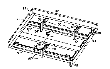
EIG. 2 is a perspective view of a platform support frame with an
embodiment of the present invention.
FIG. 3 is a cross-sectional partial view of FIG. 2.
FIG. 4 is a cross-sectional partial view of FIG. 3.
-- 4 --
w0 96/06794 . ~ .. ,5,~,,,14
,~,,c211 ~7208
FIG. 5 is a cross-sectional partial view of FIG. 2.
FIG. 6 is a cross-sectional partial view of FIG. 5.
Best Mode For Carrying Out The Invention
Referring to FIG. 1, an elevator includes an elevator car 10 and a
cuu..~ t 12 mounted in the hoistway of a building for travel between
lcL~ ' limits. The car 10 includes a frame 14 and a cab 16 attached to the
frame 14. The elevator car 10 and the CuU.It~,. . . ~,;gl" 12 are connected by aplurality of hoist ropes 18. The hoist ropes 18 extend up the hoistway from the car
10 around a drive sheave (not shown) and back down to the ~ ' 12. One
or more: . ~ ropes 20 extend from the car 10 down the hoistway and
,;,,1.~_.1... 1ly back up the hoistway to the cuu..~.-.. ,,' ' 12. The weight ofthe
' ~ ropes 20 offsets the weight of the hoist ropes 18. One end of a
traveling cable 24 is also attached to the underside ofthe car 10. The other end of
the traveling cable 24 is attached to a fixed position 27 within the hoistway.
The hoist ropes 18, ~ . 6 ropes 20, and the traveling cable 24
shown in F;G. I all attach to a platform support frame 28 attached to the frame 14
of the car 10. The car fi~me 14 includes a pair of vertical stiles 32 connected on the
top by a crosshead 34 and on the bottom by a safety plank 36. The platform
support frame 28, as shown in FIG. 2, consists of a front member 38, a pair of
center members 40, a rear member 42, and a pair of side members 44. For purposesof better illustrating the present invention, FIG. 2 shows the platform support frame
28 by itself, in an perspective view taken from below the platform support frame 28.
The front 38, rear 42, and center 40 members have a "C"-shaped cross section.
Small openings 46 (see FIG. 5) cut into the "C"-shaped cross-section pcrmit the
addition or removal of adjustable weights 48, as will be discussed infra. The front
38, rear 42, center 40 and side 44 members are ~,u..~ . attached to one
amother.
W096/06794 I~,l/lJ_,','~,S,l.~ --
2 1 97208
The Adjustable Connector
The platform support frame 28 further includes adjustable connectors 50 for
connecting the, , ~ ropes 20 and traveling cable 24 (FIG. I) to the
platform support frame 28. Each adjustable connector 50, as shown in FIGS. 2-4,
consists of a "C"-shaped beam 52 and a plate 54. The beams 52 extend between a
center 40 member and one of either the front 38 or rear 42 member. A
c~ l flange 56 (FIG. 3) is attached to each end of the beam 52. The
,c...~,..l flanges 56 fit over the opening of the "C"-shaped beam 52 and bends
around a lower portion of the beam 52 to provide additional support . FIG. 2 shows
three adjustable connectors 50 attached to the platform support firame 28.
Cum.l.~ , available rail clips 58, shown in FIGS. 3 and 4, are used to attach
each beam 52 to one of the center members 40 and to one of the front 38 or back 42
members, depending on the application. Specifically, a rail clip 58 is fastened to the
underside of each end of the beam 52 using a ~.UII . . ' ~ ' fastener 60.
The plate 54 connected to each beam 52 allows for variable positioning
along the beam 52. Holes 62 in each plate 54 (see FIG. 3) receive fasteners (notshown) for fixing the ,,.. ~ B ropes 20 (FIG. I) or traveling cables 24 to the
plate 54. The plate 54 includes a hooked flange 64 which rests on top of the beam
52. A clamping assembly 66 attaches the plate 54 to beam 52. The clamping
assembly 66 (see FIG. 4) consists of an "L"-shaped bracket 68, a bolt 70, and a self
locking hex nut 72. The "L"-shaped bracket 68 is positioned inside of the "C"
shaped cross-section of the beam 52 and secured to the plate 54 by the bolt 70 and
nut 72. The plate 54 may be slid along the length of the beam 52 to establish the
correct position. The upper and lower lip of the beam 52 prevents the "L"shaped
bracket 68 from sliding out ofthe "C"-shaped beam 52.
-- 6 -
W0 96/06794 . r r~ 4
"~'''2'1'97208
The Adjustable Weight
Rèferrjng to FIGS. 5 and 6, adjustable weights 48 are attached to the
platform support firame 28 to shift the center of gravity of the car l 0, and thereby
baiance the weight of the elevator car 10 relative to the rails 76 (FIG. 1). Thenumber and size of weights 48 used will depending on weight ~ha~ .la ;~li.,~ of each
car 10. A totai of 200400 pounds will generaliy be needed to properly baiance anelevator car 10.
Each adjustable weight 48 includes a slot 77 shaped such that it can be first
slid into the "C"-shape of a front 38, rear 42, or center 40 member through one of
the smail openings 46, and ~ ly slid laterally to receive the flange of the
"C"-shaped member 38,40,42. In other words, the geometry of the "C"-shaped
members 38,40,42 and the slotted weights 48 is such that the weights 48 are
supported by the member 38,40,42 and may be moved freely in a lateral direction to
facilitate the balancing process. Each adjustable weight 48 has a tapped hole for
receiving a locking bolt 78. When tightened, the locicing bolt 78 secures the
adjustable weight 48 in a particular position.
Operation
Referring to FIG. I, during the initial instailation and balancing of the
elevator car 10 the length of the . , ~ ropes 20 and traveling cable 24 are
estabiished to ensure that there is sufficient length to prevent the ropes 20 or cable
24 from w~ ,...,nc;.~g any binding or stress at any ~ ,h; position within
the hoistway. The goai is to have each rope 20 or cable 24 be able to assume itsnatural curve at the extremes of the car /~,~.IUIII~ . _;ghl travel. Once the proper
lengths have been . ' ' ' l, each adjustable connector 50 is positioned in the spot
beiieved to maintain the rope 20 or cable 24 in its natural curve, before the
~.. ,l.. -~i.. g ropes 20 and traveling cable 24 are attached.
.
wo 9G/067g4 ;; 2 1 ~ 7 2 û 8 PCT/IJS95/09911
Referring to FIGS. 3 and 4, the position of each adjustable connector 50 is
adjusted by first loosening the rail clips 58 comnecting the beam 52 to the center
member 40 and one of the front 38 or rear 42 members. Once the beam 52 is
properly situated, the rail clips 58 are tightened thereby fixing the beam 52 in place.
Next, the plate 54 is positioned relative to the beam 52 by loosening the clamping
assembly 66 (FIG. 4) that attaches the plate 54 to the beam 52 and sliding the plate
54 along the beam 52 to the u~,~. u~ ., position. Once the clamping assembly 66 is
retightened, the plate 54 is fixed in position. The entire process for positioning an
adjustable comnector 50 as described heretofore is repeated for each connector 50
used in a given e.. ll,~ ' After all the adjustable connectors 50 are in place, the
~ 1l r ~ " ropes 20 and traveling cable 24 are connected to the respective plates
54
Upon comnecting the . . " ropes 20 and traveling cable 24 to the
elevator car 10, the center of gravity of the car 10 is likely to be off center. Thus,
adjustable weights 48, as shown in FIGS. 5 and 6, are used to help balance the car
10. The adjustable weights 48 are added, removed, and positioned on the platformsupport frame 28 via the small openings 46 as described heretofore. The number of
weights 48 needed for a given s ~ " will depend on the load weight which
must be balanced and can easily be adjusted if the positioning of the ~ ; ,g
ropes 20 or traveling cable 24 is changed.
A person of skill in the art will recognize that it is difticult at best to connect
the ~.o" .p. . ,~ g ropes 20 and traveling cable 24 to fixed hitch locations on the
platform support frame 28. One reason adjustable positioning of the ~,UIIII) " ,,
ropes 20 and traveling cable 24 is advantageous is that it allows the ~ 1, .,
ropes 20 and traveling cable 24 to hang in its natural radius, or as close to it as
possible. Another reason adjustable positioning of the ~.u" ~ ; g ropes 20 and
traveling cable 24 is ddV~ ..5_~1U~ is that it allows the ropes 20 and cables 24 to be
hung in positions that minimize the chance of ~ gl. .. 1
WO 96/06794 ~ )..,5. ~9J 1 ~
97208
Another advantage of the present invention results from the single locking
bolt 78 (FIGS. 5 and 6) necessary to attach the al ~ of the adjustable
weight 48 used in balancing the elevator car 10. Given that the adjustable weight 48
hangs freely without additional support and only requires one bolt to fix its position,
a worker can adjust the position of the weight using only one hand. This allows the
worker greater ease in both installing the adjustable weights 48 and in balancing the
elevator car 10.
A further advantage of the adjustable weight 48 results from the ease and
simplicity of its design. The adjustable weight 48 is shaped such that it can hang on
the platform support frame member 38,40,42 without additional support. This
reduces the cost and complexity of attaching the adjustable weight 48 since no
additional , are necessary. This also allows a held worker the
u~ u,u~y to check the balance of the car 10 with the entire amount of weight
supported on car prior to bolting the weight in place.
Although the invention has been shown and described with respect to a best
mode r~ o~ 1 thereof, it should be understood by those of or&nary skill in the
art that various omissions, changes and additions in the form and detail thereof may
be made without departing from the spirit and scope of the invention. For example,
the front 38, rear 42, and center 40 members ofthe platform support frame 28 have
been described heretofore as having a "C"-shaped cross-section for receiving theadjustable weights and the reinforcing flanges 56 of the adjustable COMector beams
52. Alternatively, other male and female geometries may be used.
g