Language selection

Search

Patent 2197230 Summary

Third-party information liability

Some of the information on this Web page has been provided by external sources. The Government of Canada is not responsible for the accuracy, reliability or currency of the information supplied by external sources. Users wishing to rely upon this information should consult directly with the source of the information. Content provided by external sources is not subject to official languages, privacy and accessibility requirements.

Claims and Abstract availability

Any discrepancies in the text and image of the Claims and Abstract are due to differing posting times. Text of the Claims and Abstract are posted:

  • At the time the application is open to public inspection;
  • At the time of issue of the patent (grant).
(12) Patent: (11) CA 2197230
(54) English Title: CONTAINER WITH CLOSURE CAP AND METHOD OF FILLING CONTAINERS WITHOUT GAS BUBBLES
(54) French Title: CONTENANT AVEC BOUCHON ET METHODE DE REMPLISSAGE DES CONTENANTS SANS BULLES DE GAZ
Status: Term Expired - Post Grant Beyond Limit
Bibliographic Data
(51) International Patent Classification (IPC):
  • B65D 51/16 (2006.01)
  • B65D 39/04 (2006.01)
  • B65D 51/00 (2006.01)
(72) Inventors :
  • KLADDERS, HEINRICH (Germany)
  • FREUND, BERNHARD (Germany)
  • BACHTLER, WULF (Germany)
  • JAEGER, JOACHIM (Germany)
  • EICHER, JOACHIM (Germany)
(73) Owners :
  • BOEHRINGER INGELHEIM KG
(71) Applicants :
  • BOEHRINGER INGELHEIM KG (Germany)
(74) Agent: SMART & BIGGAR LP
(74) Associate agent:
(45) Issued: 2008-12-09
(86) PCT Filing Date: 1995-08-11
(87) Open to Public Inspection: 1996-02-29
Examination requested: 2002-08-08
Availability of licence: N/A
Dedicated to the Public: N/A
(25) Language of filing: English

Patent Cooperation Treaty (PCT): Yes
(86) PCT Filing Number: PCT/EP1995/003183
(87) International Publication Number: EP1995003183
(85) National Entry: 1997-02-10

(30) Application Priority Data:
Application No. Country/Territory Date
P 44 28 434.9 (Germany) 1994-08-11

Abstracts

English Abstract


A closure cap for sealing containers without gas bubbles
displaces some of the contents of the container when
fitted onto the neck of the container and at the same
time allows any trapped gas to escape through one or
more vents before the closure cap engages in the closure
position.


French Abstract

Un capuchon de fermeture qui permet de fermer des récipients sans gaz repousse une partie du contenu du récipient lorsqu'il est posé sur le col du récipient et permet en même temps au gaz contenu dans le récipient de s'échapper par une ou plusieurs ouvertures avant que le capuchon de fermeture ne soit verrouillé dans sa position de fermeture.

Claims

Note: Claims are shown in the official language in which they were submitted.

-6-
Claims
1. Container (3) with closure cap (1) for filling with
liquids without gas bubbles, wherein means (2) is
provided which displaces part of the contents of the
container during the pushing of the closure cap (1) onto
the neck of the container (3), one or more vents (6)
being provided so that, as the container is closed with
the closure cap, a communication with the outside is
established which allows gas and/or liquid to escape
from the interior (7) of the cap.
2. Closure cap (1) for filling with liquids without
gas bubbles, wherein means (2) is provided which
displaces part of the contents of the container during
the pushing of the closure cap (1) onto the neck of the
container (3), one or more vents (6) providing a
communication between the interior (7) of the closure
cap and the exterior.
3. Closure cap (1) according to claim 2, in which the
vent or vents (6) are located in the upper or side part
of the closure cap (1).
4. Closure cap (1) according to claim 2, wherein the
vent or vents (6) consists or consist of recesses in the
bead (4).
5. Closure cap (1) according to claim 2, wherein,
instead of the vent or vents (6), one or more recesses
are provided in the cylindrical ring (5).
6. Closure cap according to one of claims 1 to 5,
characterised in that the lower part of the dipping
nozzle (10) of the closure cap (1) is chamfered.

-7-
7. Container according to claim 1, characterised in
that one or more vents (6) are provided for ventilation
in the cylindrical ring (5).
8. Container with closure cap according to claim 1,
characterised in that the vents are arranged in such a
way that, after the container has been closed, there is
no longer any communication between the vents and the
liquid inside.
9. Container according to claim 1, 7 or 8,
characterised in that the container underneath the rigid
neck of the container consists of a readily deformable
material (3b), so that the container collapses in on
itself when liquid is removed.
10. Container according to one of claims 1, 7 or 8,
characterised in that the container (3) consists of a
fixed external container (3a) and a readily deformable
inner bag (3b) which collapses in on itself as liquid is
removed.
11. Closure cap (1) for filling with liquids without
gas bubbles, wherein means (2) is provided which
displaces some of the contents of the container as the
closure cap (1) is pushed onto the neck of a container
(3), characterised in that the dipping nozzle in the
lower part is provided with a readily pierceable
membrane.
12. Closure cap according to claim 11, characterised in
that the lower part of the dipping nozzle is chamfered.
13. Closure cap according to claim 11 or 12,
characterised in that the inner part of the dipping
nozzle has guide means for a cannula.

-8-
14. Closure cap according to one of claims 11 to 13,
characterised in that the guide means (12) merges into a
press fit (14).
15. Closure cap according to one of claims 11 to 13,
characterised in that the nozzle is fitted with an o-
ring seal.
16. Process for transferring liquids, without bubbles,
into containers (3) which have a cylindrical ring (5)
encircling their neck, characterised in that in order to
close the container a closure cap (1) engaging in the
closure position is pushed onto the neck of the
container (3), the closure cap displacing the contents
of the container with means (2), and, during the fitting
on of the closure cap (1), a communication with the
exterior is provided through one or more vents or
recesses (6) in the closure cap (1), in the cylindrical
ring (5) or in the bead (4), enabling gas and/or liquid
to escape from the interior (7) of the cap.
17. Process for removing liquids from containers (3)
which contain a closure cap (1) having a dipping nozzle
(2) and a chamfered membrane (10), characterised in that
the membrane is pierced with a blunt cannula in order to
remove the liquid.

Description

Note: Descriptions are shown in the official language in which they were submitted.


2197230
.,~_ .
- 1 -
S016768J.64
Container with Closure Cap and Method of Filling
Containers without Gas Bubbles
The invention relates to a container with closure cap
for filling with liquids without gas bubbles. The
invention relates in particular to a closure cap by
means of which containers can be filled with liquids
without gas bubbles.
For numerous applications it is necessary to transfer
liquids into containers in such a way that no residual
air or gas is included. Such a requirement applies, for
example, to containers for pharmaceutical solutions
which are used in certain inhalers which meter liquids
by means of a measuring chamber (cf. for example
WO 91/14468, see Fig. 1). Since the liquid to be
metered in this case frequently contains highly
effective pharmaceutical substances which have to be
accurately metered, the range of fluctuations in the
dosage administered must be as small as possible;
otherwise, the patient will not receive the quantity of
active substance prescribed by the doctor. In view of
the tiny amount of liquid administered per dose, even
relatively small bubbles lead to high percentage
deviations in the above-mentioned inhalers.
The invention now relates to a container and more
particularly to a closure cap and a process for filling
containers without ga6 bubbles. The closure cap is
constructed so that, when placed on the neck of the
container, it displaces some of the contents of the
container and at the same time allows any gas enclosed
therein to escape and engages in the closure position.
The closure may contain means for guiding a cannula for
removing liquid from the container.

2197230
- 2 -
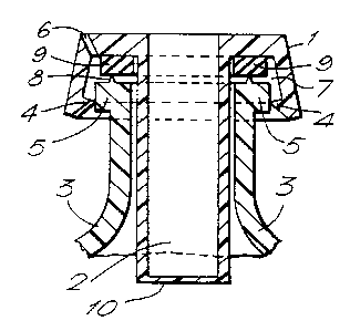
Fig. 1 shows an axial section through the centre of a
closure cap of this kind.
Fig. 2 shows, again in axial section, the neck of a
container with the closure cap according to the
invention fitted thereon in the closure position, the
vents being arranged differently.
Fig. 3 shows the embodiment according to the invention,
wherein the vents (at least one) are provided in the
form of recesses on the upper part of the container.
Fig. 3a shows an enlarged view of the embodiment
according to the invention.
Fig. 4 shows the container according to the invention
with the closure cap fitted thereon.
Fig. 5 shows a closure cap according to the invention
with guide means for the cannula for removing the
liquid.
In Fig. 1, the flexible closure cap (1) has a device (2)
- in this case in the form of a dipping nozzle - through
which some of the contents of the container (3) are
displaced during the closure process. An inner
encircling bead (4) (crimped edge) on the lower rim of
the closure cap (1) engages in the closure position
below a cylindrical ring (5) running around the outside
of the neck of the container. Whilst the closure cap
(1) is being pushed on, the rim of the closure cap
expands and the bead (4) abuts on the ring (5) to form a
seal, so that the only communication between the
interior (7) of the cap and the exterior is through one
or more vents (6). In the closure position the gap
between the flat part of the closure cap (1) and the
upper edge of the neck of the container, which may

2197230
- 3 -
optionally be provided with an encircling rib (8) to
improve the seal, is filled by a sealing ring (9) and in
this way the interior of the container (3) is reliably
sealed off from the interior (7) of the cap, which
surrounds the sealing ring (9) and the neck of the
container (3). The internal diameter of the sealing
ring (9) is preferably selected so that it fits tightly
against the device (2). The vent or vents (6) may also
be located at other points on the exterior of the cap,
possibly on the side, in the cylindrical part of the
cap.
Fig. 2 shows the neck of the container with the closure
cap (1) fitted thereon in the closure position.
However, in this case, venting is achieved by the fact
that vents (6) in the form of recesses are provided in
the encircling bead (4) of the closure cap (1).
Alternatively, recesses in the ring (5) may also serve
as venting means (see Fig. 3). The dipping nozzle (2)
is sealed off by a membrane (10) at the lower end. In
order to remove liquid, the membrane is pierced with a
cannula.
Figure 3 shows, again in axial section, the neck of a
container with the closure cap fitted thereon during the
closing process. As shown in Fig. 3, there is at least
one vent (6) in the ring (5) of the container.
Preferably, the vents are arranged in the form of
recesses in the ring (5). Alternatively, the vents may
be provided in the form of bores. The vents (6) are
arranged in such a way that the air can escape from the
interior (7) of the cap during the closure process
through the vents (6), but after the container has been
sealed there is no longer any communication between the
liquid inside the container and the vents.
Fig. 4 shows, in axial section, a container according to

2197230
- 4 -
the invention with a closure cap fitted thereon, the
vent or vents being provided in the outer part of the
ring (5). The vents may be provided in the form of
recesses.
In a preferred embodiment, the container (3) consists of
a dimensionally stable outer container and a readily
deformable inner bag (3b) which collapses onto itself as
the liquid is removed. In these embodiments, any
residual air bubbles would be particularly detrimental.
Such containers are described, for example, in European
Patent 532873, the contents of which are hereby referred
to. The device (11) serves to secure the deformable
inner bag (3b) to the inner wall of the fixed external
container (3a) facing the bag (3b).
Figure 5a shows a preferred embodiment of the closure
cap according to the invention, in which the interior of
the dipping nozzle is constructed so as to form a guide
(12) for a cannula for the removal of liquid. In the
present instance the vents (6) are provided on the upper
part of the container (3). As already described, the
vents may alternatively be provided on the closure cap.
Figures 5b and 5c show other embodiments with regard to
the construction of the dipping nozzle (2) and the guide
(12) for the cannula for removing liquid.
Figure 5b shows an embodiment in which the guide (12)
merges into a press fit (14). The press fit is
designed, in terms of diameter and length, so that on
the one hand the resistance to the insertion of the
cannula is minimised and on the other hand an adequate
seal is achieved between the nozzle and cannula.
Fig. 5c shows an embodiment having a flexible 0-ring
seal (13) between the nozzle and the inserted cannula,
in which the cannula is not shown.

?197230
- 5 -
As shown in Figs. 5b and 5c, the lower end of the
dipping nozzle with the membrane (10) may preferably be
chamfered, preferably by 40 to 70 relative to the
nozzle axis. This makes it easier for the membrane to
be pierced by a "blunt" cannula the end face of which is
perpendicular to the axis of the cannula. The
advantages of a blunt as opposed to a sharpened cannula
are the lower risk of injury to the user, the reduced
labour involved in producing the end face of the cannula
and the reduced risk of particle abrasion on the nozzle
wall when the cannula is inserted.
The drawings show a sealing ring (9) and an encircling
rib (8). In an alternative embodiment the encircling
rib (8) may be omitted if all the parts are manufactured
with high precision to fit exactly.
In order to remove liquid from the container (3) the
membrane (10) is pierced with a cannula. The preferred
embodiments are those wherein the container (3) has a
readily deformable inner bag (3b) and the tip of the
cannula is located half way up the container when the
liquid is removed. In this case, air bubbles are least
problematic.
The container and closure cap (1) are generally made of
plastics material. Since the liquid transferred into
the container is not compressible in practice, the
system comprising the container and closure cap must be
sufficiently deformable to allow expansion of the liquid
in heat. Similarly, when the liquid is removed the
walls of the container must be capable of yielding
sufficiently or collapsing. Suitable plastics,
consisting of polyethylene or polypropylene, for
example, are available to those skilled in the art for
the manufacture of these containers and for the closure
cap (1) .

Representative Drawing
A single figure which represents the drawing illustrating the invention.
Administrative Status

2024-08-01:As part of the Next Generation Patents (NGP) transition, the Canadian Patents Database (CPD) now contains a more detailed Event History, which replicates the Event Log of our new back-office solution.

Please note that "Inactive:" events refers to events no longer in use in our new back-office solution.

For a clearer understanding of the status of the application/patent presented on this page, the site Disclaimer , as well as the definitions for Patent , Event History , Maintenance Fee  and Payment History  should be consulted.

Event History

Description Date
Inactive: IPC expired 2023-01-01
Inactive: Expired (new Act pat) 2015-08-11
Grant by Issuance 2008-12-09
Inactive: Cover page published 2008-12-08
Inactive: Final fee received 2008-09-22
Pre-grant 2008-09-22
Notice of Allowance is Issued 2008-04-28
Letter Sent 2008-04-28
Notice of Allowance is Issued 2008-04-28
Inactive: Approved for allowance (AFA) 2008-03-28
Amendment Received - Voluntary Amendment 2008-02-05
Inactive: S.30(2) Rules - Examiner requisition 2007-08-06
Amendment Received - Voluntary Amendment 2006-12-08
Inactive: S.30(2) Rules - Examiner requisition 2006-06-08
Inactive: IPC from MCD 2006-03-12
Amendment Received - Voluntary Amendment 2005-10-12
Inactive: S.30(2) Rules - Examiner requisition 2005-04-12
Inactive: Application prosecuted on TS as of Log entry date 2002-08-27
Letter Sent 2002-08-27
Inactive: Status info is complete as of Log entry date 2002-08-27
Request for Examination Requirements Determined Compliant 2002-08-08
All Requirements for Examination Determined Compliant 2002-08-08
Letter Sent 1997-12-15
Inactive: Applicant deleted 1997-08-13
Inactive: Courtesy letter - Evidence 1997-03-18
Application Published (Open to Public Inspection) 1996-02-29

Abandonment History

There is no abandonment history.

Maintenance Fee

The last payment was received on 2008-07-23

Note : If the full payment has not been received on or before the date indicated, a further fee may be required which may be one of the following

  • the reinstatement fee;
  • the late payment fee; or
  • additional fee to reverse deemed expiry.

Patent fees are adjusted on the 1st of January every year. The amounts above are the current amounts if received by December 31 of the current year.
Please refer to the CIPO Patent Fees web page to see all current fee amounts.

Owners on Record

Note: Records showing the ownership history in alphabetical order.

Current Owners on Record
BOEHRINGER INGELHEIM KG
Past Owners on Record
BERNHARD FREUND
HEINRICH KLADDERS
JOACHIM EICHER
JOACHIM JAEGER
WULF BACHTLER
Past Owners that do not appear in the "Owners on Record" listing will appear in other documentation within the application.
Documents

To view selected files, please enter reCAPTCHA code :


To view images, click a link in the Document Description column. To download the documents, select one or more checkboxes in the first column and then click the "Download Selected in PDF format (Zip Archive)" or the "Download Selected as Single PDF" button.

List of published and non-published patent-specific documents on the CPD .

If you have any difficulty accessing content, you can call the Client Service Centre at 1-866-997-1936 or send them an e-mail at CIPO Client Service Centre.


Document
Description 
Date
(yyyy-mm-dd) 
Number of pages   Size of Image (KB) 
Representative drawing 1997-10-13 1 8
Abstract 1995-08-10 1 9
Description 1995-08-10 5 212
Claims 1995-08-10 3 99
Drawings 1995-08-10 3 68
Description 2005-10-11 7 275
Claims 2005-10-11 3 98
Description 2006-12-07 7 278
Claims 2006-12-07 3 108
Claims 2008-02-04 3 105
Description 2008-02-04 7 284
Representative drawing 2008-03-30 1 9
Courtesy - Certificate of registration (related document(s)) 1997-12-14 1 116
Reminder - Request for Examination 2002-04-14 1 119
Acknowledgement of Request for Examination 2002-08-26 1 177
Commissioner's Notice - Application Found Allowable 2008-04-27 1 165
PCT 1997-02-09 45 2,205
Correspondence 1997-03-17 1 42
Correspondence 2008-09-21 1 39