Language selection

Search

Patent 2197248 Summary

Third-party information liability

Some of the information on this Web page has been provided by external sources. The Government of Canada is not responsible for the accuracy, reliability or currency of the information supplied by external sources. Users wishing to rely upon this information should consult directly with the source of the information. Content provided by external sources is not subject to official languages, privacy and accessibility requirements.

Claims and Abstract availability

Any discrepancies in the text and image of the Claims and Abstract are due to differing posting times. Text of the Claims and Abstract are posted:

  • At the time the application is open to public inspection;
  • At the time of issue of the patent (grant).
(12) Patent Application: (11) CA 2197248
(54) English Title: FLOAT DEVICE
(54) French Title: FLOTTEUR
Status: Deemed Abandoned and Beyond the Period of Reinstatement - Pending Response to Notice of Disregarded Communication
Bibliographic Data
Abstracts

English Abstract


A truncated cone-shaped float is provided, with a number of fins displaced evenly around
the circumference of the float, and attachment means for attaching the invention to water
level monitoring gear.
The float device is used to provide accurate long-term water level monitoring data in
small diameter wells.


French Abstract

Flotteur en forme de cône tronqué, comprenant de nombreux ailerons distribués également autour de sa circonférence et un dispositif de fixation permettant d'attacher le flotteur à des instruments de surveillance de niveau d'eau. Le flotteur permet d'obtenir des données précises, à long terme, relatives au niveau d'eau dans des puits de petit diamètre.

Claims

Note: Claims are shown in the official language in which they were submitted.

Claims Not Yet Available

Description

Note: Descriptions are shown in the official language in which they were submitted.


2~972~8
-
FLOAT DEVICE:
This invention deals with accurate long-term groundwater monitoring in small diameter
wells.
BACKGROUND OF THE INVENTION:
The use of instruments in obtaining accurate long term water level data is difficult and
expensive. Some of the methods in the prior art which have been used to date with
limitations to their utility and cost efficiency are submersible pressure transducers, which
tend to drift over a period of time, and float operated water level recorders which are
limited in their utility by their requirement of a fairly large diameter and plumb well - i.e.
with a diameter greater than fifteen centimeters. A crooked well will cause such a float to
adhere to the well casing and result in poor water level recordings. Water levelmonitoring wells of 5 and 12 centimeter diameters are becoming standard in the industry
and, as such, the float operated water level recorders are limited in their utility to this
extent as well.
The present invention deals with a float device to be used to obtain such water level
monitoring data, such improved float representing an improvement over the current art in
a number of ways, including:
1. the shape and small surface of the invention minimi~s the friction and
capillary attraction forces;
2. a low center of gravity, with more than eighty percent of the float being
submerged, provides stable flotations;

Z' 21972~8
3. the design assures adequate pushing and pulling;
4. used in conjunction with a shaft encoder, the device is capable of
supplying accurate long-term water level data from water level monitoring
wells as small as five centimeters in diameter.
SUMMARY OF THE INVENTION:
The object of the invention is to provide accurate long-term water level monitoring data
in small diameter wells.
~ The invention consists of a truncated cone shaped float. The bottom of the columnar float
is tapered and sealed. The top~ of the columnar float also has a tapered and sealed end.
The tapered shape of the top of the columnar float enables water level measuring devices
to get past the float.
Below the tapered top of the columnar float are eight fins equally spaced around the
circumference of the float. The truncated shape of the float along with the fins reduce the
capillary attraction between the device and the well casing. The fins provide minimum
float friction against the casing wall and allow for the float to pass by casing joints.
Within the columnar float is a weight, attached in position as to m~ximi7.e the reliability
and stability of the floating action of the device.
An eye hook is on top of the tapered top end of the columnar float to attach to the
remainder of the water level monitoring gear.

~3 ~197~4~
DESCRIPTION OF THE DRAWINGS:
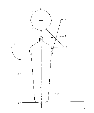
The attached preliminary figure is an elevated cross-sectional view of one embodiment of
the device.
DETAILED DESCRIPTION OF THE DRAWINGS:
The concept~ li7~1ion of the invention is demonstrated in the attached preliminary figure,
which shows one embodiment of the invention. This embodiment of the device 1
consists of a float 2, which in this embodiment has the shape of a truncated cone-shaped
column of a certain width and a certain length. At one end of the cone-shaped float 2,
being the end of the cone-shaped float 2 which will be under water in operation of the
device, is a tapered end 5 which closes off the columnar float 2. The other end 3 of the
columnar float 2, being the top end of the float, is also tapered to seal off the float.
The dimensions of the device 1, being the width of the columnar aspect of the float and
the length 4 of the device, could be varied to produce floats for use in various sized wells
~ and to take account of other circumstances otherwise affecting the use of the device 1. It
will be understood that these variations and adjustments in the dimensions of the device
are contemplated within the scope of the present invention.
The present embodiment of the invention also includes a number of fins 7 spaced
equidistantly around the circumference of the top end 3 of the float. In the present
embodiment the number of fins 7 is eight. These fins 7 reduce any friction of the float
device 1 against the well casing and enable the float device 1 to ride over joints in the
well casing. The fins 7 also result in min;mum capillary attraction between the float
device 1 and the well casing.

~lg72~
Further, in the present embodiment there is a weight 8 positioned and attached within the
~ float 2 to regulate the operation of the device 1 and to provide further stability in the
water. Varying weights and positions of the weight are contemplated.
There is attached to the top end 3 of the float device an eye hook 9 to facilitate the
attachment of the device 1 to a cable extending down the shaft of the water level
monitoring well. Varying clasps and attachments could be used and it will be understood
that these are contemplated within the scope and intent of the claimed invention.
The float device 1 could be used for varying well depths. The device 1 has to date been
tested and used in wells up to seven meters deep.
It is envisioned that the float device 1 could be m~nllf~ctured of a number of materials,
including plastic or stainless steel. It will be understood that various building materials
are contemplated within the scope of the claimed invention.
The float device 1 could be used to monitor levels in water wells, as well as the levels of
other fluids in tanks and other containers. To monitor fluids of different viscosities or
specific gravities the dimensions or weight of the device 1 might be adjusted and it will
be understood that these alterations are contemplated within the scope of the present
mventlon.

Representative Drawing
A single figure which represents the drawing illustrating the invention.
Administrative Status

2024-08-01:As part of the Next Generation Patents (NGP) transition, the Canadian Patents Database (CPD) now contains a more detailed Event History, which replicates the Event Log of our new back-office solution.

Please note that "Inactive:" events refers to events no longer in use in our new back-office solution.

For a clearer understanding of the status of the application/patent presented on this page, the site Disclaimer , as well as the definitions for Patent , Event History , Maintenance Fee  and Payment History  should be consulted.

Event History

Description Date
Application Not Reinstated by Deadline 2000-02-11
Time Limit for Reversal Expired 2000-02-11
Inactive: Cover page published 1999-10-05
Deemed Abandoned - Failure to Respond to Maintenance Fee Notice 1999-02-11
Letter Sent 1999-01-13
Application Published (Open to Public Inspection) 1998-08-11
Inactive: Applicant deleted 1997-08-13
Inactive: Inventor deleted 1997-08-13
Inactive: Applicant deleted 1997-08-13

Abandonment History

Abandonment Date Reason Reinstatement Date
1999-02-11
Owners on Record

Note: Records showing the ownership history in alphabetical order.

Current Owners on Record
ED JAWORSKI
DENNIS ZLIPKO
Past Owners on Record
None
Past Owners that do not appear in the "Owners on Record" listing will appear in other documentation within the application.
Documents

To view selected files, please enter reCAPTCHA code :


To view images, click a link in the Document Description column (Temporarily unavailable). To download the documents, select one or more checkboxes in the first column and then click the "Download Selected in PDF format (Zip Archive)" or the "Download Selected as Single PDF" button.

List of published and non-published patent-specific documents on the CPD .

If you have any difficulty accessing content, you can call the Client Service Centre at 1-866-997-1936 or send them an e-mail at CIPO Client Service Centre.

({010=All Documents, 020=As Filed, 030=As Open to Public Inspection, 040=At Issuance, 050=Examination, 060=Incoming Correspondence, 070=Miscellaneous, 080=Outgoing Correspondence, 090=Payment})


Document
Description 
Date
(yyyy-mm-dd) 
Number of pages   Size of Image (KB) 
Abstract 1997-05-13 1 9
Claims 1997-05-13 1 12
Drawings 1997-05-13 1 10
Description 1997-05-13 4 132
Representative drawing 1998-08-25 1 5
Notice: Maintenance Fee Reminder 1998-11-15 1 118
Courtesy - Abandonment Letter (Maintenance Fee) 1999-03-10 1 187
Second Notice: Maintenance Fee Reminder 1999-08-11 1 129
Notice: Maintenance Fee Reminder 1999-11-14 1 119
Correspondence 1999-01-12 3 136
PCT Correspondence 1998-02-19 1 10
Courtesy - Office Letter 1997-03-03 1 21