Note: Descriptions are shown in the official language in which they were submitted.
1162-57
2197371
ELECTRICAL CONNECTOR
FIELD OF THE INVENTION
The invention relates to an electrical
l0 connector and more particularly to an electrical
connector which can be used in exterior environmental
conditions.
BACKGROUND OF THE INVENTION
Electrical connectors are used in exterior
environments to connect wires with various devices. The
exterior environments may include agricultural equipment,
construction equipment or other vehicles which may be
exposed to the weather, such as, moisture and temperature
extremes. In addition, such electrical connectors are
subjected to vibration from the engine or the movement of
the vehicle. Thus, the electrical connector should
withstand these operating conditions.
In addition, it is necessary to attach the
electrical connector to the individual wires.
Specifically, the individual wire is attached to an
electrical contact. The electrical contact with the
attached wire is then assembled into the housing for the
electrical connector. This process may be performed by
an individual and therefore, can be relatively expensive.
OBJECTS OF THE INVENTION
A general object of the present invention is to
provide an electrical connector which can withstand
environmental conditions for the particular application.
Another object of the invention is to provide an
electrical connector which reduces the manufacturing and
~. 2197371
2
assembly costs. An additional object of the invention is
to provide an electrical connector which minimizes the
number of components for the electrical connector.
Another object of the invention is to provide
alignment features for each of the components so that the
components can be assembled in only one specific
orientation. A further object of the invention is to
provide higher contact retention so that the contact
cannot be unintentionally removed from the electrical
connector. Another object of the invention is to provide
a secondary lock which confirms that the contact is
properly positioned and also improves the retention of
the contact in the electrical connector. Another object
of the invention is to provide a secondary lock with a
first position which retains the secondary lock in a
partially inserted position and a second position which
locks the contact into the insulator after the contact
has been inserted.
A further object of the invention is to reduce
the amount of insulator material used in the electrical
connector. An additional object of the invention is to
provide a contact removal tool which is included in the
electrical connector and can be used by a repair person
in a remote location.
Also, an object of the invention is to provide
a backplate which prevents the grommet from being
disassembled when a wire and contact are removed from the
electrical connector. An additional object is to provide
a backplate which assists the grommet in maintaining an
environmentally resistant seal. Another object of the
invention is to provide a backplate which orients the
contact for proper insertion.
An additional object is to provide an
electrical connector with "push to seat" contacts versus
"pull to seat" contacts. A further object is to provide
an electrical connector which includes a water shield.
2197371
3
A further object is to provide an electrical connector
which is available in different sizes depending upon the
number of contacts which are required.
Other objects and advantages of the invention
will become apparent upon reading the following
description and upon reference to the drawings.
SUMMARY OF THE INVENTION
The electrical connector may include a housing,
a contact, a secondary lock, a grommet, a backplate, a
bolt, a contact removal tool, and a splash guard. The
housing includes openings which receive the contacts.
The contact is crimped onto the wire to create the
contact and wire assembly.
The grommets are positioned in cavities at the
rear of the housing. The grommets form a relatively
weather resistant seal. The electrical connector may
also include the backplate. The housing and backplate
are designed so that the grommets are subjected to
compressive forces in order to enhance the sealing
characteristic of the grommets.
As the contact is inserted, a locking tab is
deflected upward when the contact engages the ramp. The
ramp engages an opening in the contact and prevents the
contact from being removed from the housing.
Although the locking tab will prevent the
contact from being removed, the secondary locks will
increase the retention of the contact in the electrical
connector. In addition, the secondary lock may include a
feature which permits the partial insertion of the
secondary lock prior to insertion of the contact and wire
assembly. The secondary lock also assures that the
contacts have been properly inserted.
The electrical connector may also include a
splash guard which would assist in deflecting water from
the rear of the electrical connector. The electrical
connector may also include a removal tool which may be
CA 021197371 2004-10-15
4
used to remove contacts from the electrical connector. The
removal tool can be stored in the backplate.
In one aspect, the present invention seeks to provide
an electrical connector for connection to a device or
second connector comprising a housing having a contact
passageway for housing a contact therein for engaging a
mating contact of a device or a second connector, a grommet
adjacent said housing and having an opening for receiving a
contact, and a backplate adjacent said grommet and having
an opening for receiving a contact.
In another aspect, the present invention seeks to
provide an electrical connector for connection to a device
or second connector comprising a housing having a contact
passageway for housing a contact therein for engaging a
mating contact of a device or a second connector, said
housing includes a locking tab to hold a contact, a
secondary lock attached to said housing, said secondary
lock to hold a contact, said secondary lock is attached to
said housing in a first position and a second position.
In another aspect, the present invention seeks to
provide an electrical connector for connection to a device
or second connector comprising a housing having a contact
passageway for housing a contact therein for engaging a
mating contact of a device or a second connector, and a
contact removal tool, said tool is stored in said housing.
In another aspect, the present invention seeks to
provide an electrical connector for connection to a device
or second connector comprising a housing having a contact
passageway for housing a contact therein for engaging a
mating contact of a device or a second connector, a
backplate adjacent said housing and having an opening for
receiving a contact, and a contact removal tool, said tool
is stored in said backplate.
CA 021197371 2004-10-15
4a
In another aspect, the present invention seeks to
provide a method for removing a contact from an electrical
connector comprising providing an electrical connector
which includes a contact removal tool, removing said
contact removal tool from said connector, inserting said
contact removal tool to remove said contact.
In another aspect, the present invention seeks to
provide an electrical connector for connection to a device
or second connector comprising a housing having a contact
passageway for housing a contact therein for engaging a
mating contact of a device or a second connector, a
backplate adjacent said housing and having an opening for
receiving a contact, said opening and a contact having a
specific relationship such that a contact can be inserted
into said opening in only one specific orientation.
In another aspect, the present invention seeks to
provide an electrical connector for connection to a device
or second connector comprising a housing having a contact
passageway for housing a contact therein for engaging a
mating contact of a device or a second connector, a grommet
adjacent said housing and having an opening for receiving a
contact, said housing having a front surface and a rear
surface, said rear surface includes a post, said grommet
includes a recess which mates with said post, said post and
said grommet having a mating relationship such that said
grommet can be mated to said rear surface in only one
specific orientation.
In another aspect, the present invention seeks to
provide an electrical connector for connection to a device
or second connector comprising a housing having a contact
passageway for housing a contact therein for engaging a
mating contact of a device or a second connector, a contact
CA 021197371 2004-10-15
4b
located in said passageway, said passageway and said
contact having a specific relationship such that said
contact can be inserted into said passageway in only one
specific orientation.
In another aspect, the present invention seeks to
provide an electrical connector for connection to a device
or second connector comprising a housing having a contact
passageway for housing a contact therein for engaging a
mating contact of a device or a second connector, and a
bolt, said housing includes a bolt aperture and said bolt
is positioned in said aperture, said housing and said bolt
having a specific relationship which retains said bolt in
said aperture.
BRIEF DESCRIPTION OF THE DRAWINGS
FIG. 1 is a left front perspective view of an
electrical connector constructed in accordance with the
teachings of the invention;
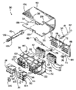
FIG. 2 is an exploded view of the electrical
connector;
FIG. 3 is a front view of the electrical connector
without the optional splash guard;
FIG. 4 is a cross sectional view of the electrical
connector taken along line 4--4 of FIG. 3;
FIG. 4A is a cross-sectional view similar to FIG. 4
except the secondary lock is in the preload position and
without the contacts and hood;
FIG. 5 is a cross sectional view of the electrical
connector shown in FIG. 4 which is mated to a device or
another electrical connector;
FIG. 6 is an enlarged cross sectional view of the area
shown in FIG. 5;
FIG. 7 is a cross sectional view of the electrical
connector taken along line 7--7 of FIG. 3;
CA 02197371 2004-10-15
4c
FIG. 8 is a left front perspective view of the
electrical contact and an attached electrical wire;
FIG. 9 is a top plan view of the electrical connector
without the optional splash guard;
FIG. 10 is a bottom plan view of the electrical
connector without the optional splash guard;
FIG. 11 is a right side view of the electrical
connector without the optional splash guard;
FIG. 11A is a left side view of the electrical
connector without the optional splash guard;
FIG. 12 is a rear view of the electrical connector
without the optional splash guard;
FIG. 13 is a cross sectional view of the secondary
lock taken along line 13--13 of FIG. 2;
25
2197371
Fig. 14 is a fragmentary cross sectional view
of the removal tool in the storage position taken along
line 14-14 of Fig. 12;
Fig. 14A is a fragmentary cross-sectional view
5 taken along line 14A-14A of Fig. 14;
Fig. 15 is a fragmentary cross sectional view
of the removal tool during the extraction from the
storage position;
Fig. 16 is a fragmentary cross sectional view
of the removal tool during the extraction from the
storage position;
Fig. 17 is a fragmentary cross sectional view
of the removal tool during the extraction from the
storage position; and
Fig. 18 is an enlarged cross sectional view
similar to Fig. 6 showing the removal tool inserted into
the electrical connector to lift the locking tab and
release the contact for removal of the contact.
DESCRIPTION OF THE EMBODIMENT
An electrical connector 30 constructed in
accordance with the teachings of the invention is
illustrated in Fig. 1. As shown in Fig. 2, the
electrical connector 30 may include an insulator housing
32, a contact 34, a secondary lock 36, 38, grommets 40,
42, backplate 44, bolt 46, contact removal tool 48, and
splash guard 50.
The insulator housing 32 includes openings 52
which receive the contacts 34. The openings 52 include
grooves 54 which are shown in Figs. 4A and 6. As will be
discussed below, the grooves 54 will engage protrusions
56 on the contacts 34 to align and support the contacts
34.
Referring to Fig. 8, the contact 34 includes
protrusions 56 and opening 58. The contact 34 is crimped
onto the wire 60 to create the contact and wire assembly
61. The contact 34 is attached to the wire 60 either
2197371
6
manually or by use of an automatic wire stripping and
contact crimping machine. In order to facilitate use of
the machine, the contacts 34 are available in a strip and
positioned in side-by-side relationship.
The grommets 40, 42 are positioned in cavities
at the rear of the housing 32. The grommets 40, 42
include apertures 62 which correspond with the openings
52 in the housing. The apertures 62 are chamfered on
each side of the grommet. The grommets 40, 42 may also
include ribs 64 which will engage the housing 32 to form
a relatively weather resistant seal. The grommets 40, 42
include a recess 66 which engages a mating post on the
housing 32. The recess 66 and post assure the proper
orientation of the grommet with the housing.
The electrical connector may also include the
backplate 44. The backplate 44 includes openings 68
which correspond with the array or configuration of the
aperture 62 and openings 52. The backplate 44 also
includes aperture 70 to receive bolt 46. The flanges 72,
73 and openings 74 are used to attach the backplate to
the housing. Referring to Figs. 2, 4A and 9, the housing
includes protrusions 76, 77 which engage the flanges 72,
73 and openings 74 to hold the backplate in position.
The housing 32 and backplate 44 are designed so that the
grommets 40, 42 are subjected to compressive forces in
order to enhance the sealing characteristics of the
grommets.
The spacing between the upper protrusions 76 is
slightly less than the spacing between the lower
protrusions 77. Similarly, the spacing between the upper
flanges 72 is slightly less than the spacing between the
lower flanges 73. The spacing of the lower flanges 73
corresponds to the spacing of the lower protrusions 77
and the spacing of the upper flanges 72 corresponds to
the spacing of the upper protrusions 76. Consequently,
the backplate 44 can be assembled to the housing 32 in
only one specific orientation.
2197371
7
After the grommets 40, 42 and backplate 44 have
been assembled to the housing 32, the contact and wire
assemblies 61 can be inserted into the appropriate
opening 68 in the backplate. As shown in Figs. 2, 4A and
12, the opening 68 includes grooves 78 similar to grooves
54 in the housing. The protrusions 56 on the contact
engage the grooves 78 to maintain the proper alignment of
the contact 34. The grooves 78 are configured so that
the contact 34 can be inserted in only one specific
orientation. The contact 34 is then pushed through the
corresponding aperture 62 in the grommet.
Referring to Figs. 5 and 6, the contact is then
inserted into the corresponding opening 52 in the
housing. As noted above, the openings 52 include grooves
54 on two opposite sides of the rectangular openings 52.
The protrusions 56 on the contact engage the grooves 54
to assure proper alignment of the contact and to support
the contact in the housing. The grooves 54 are
configured so that the contact 34 can only be inserted in
one specific orientation.
As the contact 34 is inserted to~the left in
Figs 4A and 6, the locking tab 80 is deflected upward
when the contact engages the ramp 82. As the contact
moves to the left in Figure 6, the ramp 82 engages the
opening 58 in the contact 34. The opening 58 and the
locking tab 80 which includes ramp 82 prevents the
contact from being removed from the housing by limiting
the movement of the contact to the right in Fig. 6. In
addition, the housing includes a stop 84 which limits the
movement of the. contact 34 to the left as shown in Fig.
6. The process is then repeated for each contact and
wire assembly 61.
As shown in Fig. 12, the backplate 44 includes
indicia 86 to identify the columns and rows. The indicia
may include letters and numbers. This indicia may assist
in the proper placement of contacts during assembly or
during repair. As shown in Fig. 3, corresponding indicia
'' 2197371
8
88 may be located on housing 32 to facilitate assembly or
repair.
Although the locking tab 80 will prevent the
contact from being removed, certain uses of the
electrical connector may require the use of secondary
locks 36, 38. The secondary locks will increase the
retention of the contact in the electrical connector. In
addition, the secondary lock may include a feature which
permits the partial insertion of the secondary lock prior
to insertion of the contact and wire assembly. This
preload feature permits partial assembly prior to
shipment and permits successive assembly operations.
As shown in Fig. 4A, the secondary lock 36 is
partially inserted into the housing. The secondary lock
includes protrusions 96 and the housing 32 includes
detents which will engage the protrusions 96. The
detents and the protrusions hold the secondary lock in
the preload position which is shown in Fig. 4A. The
secondary lock will remain in this position until a
sufficient force is applied to the left or right in Fig.
4A to remove or fully insert the secondary lock.
After the contact and wire assemblies 61 have
been fully inserted into the appropriate positions in the
housing, the secondary locks 36, 38 can be fully inserted
as shown in Figs. 4 and 6. Referring to Figs. 6 and 13,
the secondary lock includes three shelves 98. Referring
to Fig. 6, the shelves 98 are adjacent to the locking
tabs 80 when the secondary lock is fully inserted. The
shelves 98 prevent the locking tabs 80 from deflecting
upward and releasing contact 34. Thus, the secondary
lock provides additional retention of the contact 34 in
the electrical connector.
The secondary lock 36, 38 also assures that
the contacts 34 have been properly inserted. If a
contact has not been fully inserted, then the locking tab
80 will be deflected upward which will prevent the full
insertion of the secondary lock. Therefore, if the
2197371
9
secondary lock cannot be fully inserted, the contacts can
be.checked to determine proper insertion.
The secondary locks also have a feature to lock
the secondary locks into the housing. Referring to Fig.
2, the secondary locks 36, 38 includes locking tabs 100
with protrusions 102. The locking tabs 100 engage
detents in the housing 32. The locking tabs 100 and
detents hold the secondary lock in the fully inserted
position as shown in Figs. 4 and 6.
Referring to Figs. 2 and 3, the secondary locks
36, 38 also include apertures 104 which correspond with
the apertures and openings in the housing, grommets and
backplate. Finally, referring to Fig. 6, the shelves 98
also provide additional insulation between the rows of
contacts to prevent contacts from touching each other.
Referring to Fig. 4A, it can now be appreciated
that the secondary locks 36, 38 when in the preload
position will not interfere with the insertion of the
contacts 34. Specifically, as the contact 34 is inserted
into the aperture 52 the locking tab 80 will be able to
deflect without interference from the shelves 98.
However, depending upon the desired assembly process, the
secondary locks would not be inserted into the housing 32
until the contact and wire assembly 61 had been inserted
into the connector. In addition, the preload feature
could be eliminated.
Referring to Figs. 5 and 6, a mating connector
or device 106 is mated to the electrical connector. The
connector or device 106 includes contacts 108 which
engage the corresponding contacts 34. The contacts 34
include a first cantilever portion 110 and a second
cantilever portion 112. Prior to insertion of the mating
contact 108 the first and second cantilever portions 110,
112 are angled upward. Upon insertion of the mating
contact 108, the first and second cantilever portions are
deflected downward as shown in Fig. 6. Due to the
characteristics of the metal, the cantilever portions
2197371
continue to exert an upward force upon mating contact 108
in order to assure continuous electrical connection.
Furthermore, as the mating contact 108 is inserted into
the contact 34, the first cantilever portion 110 performs
5 a wiping action which removes debris and oxidation from
the contact 34 and mating contact 108 to assure a good
electrical connection.
After the contact and wire assemblies 61 are
inserted and the secondary locks 36, 38 have been
10 inserted, the bolt 46 may be inserted into the electrical
connector. Conversely, the bolt could be inserted prior
to the insertion of the contact and wire assemblies 61.
Referring to Figs 2 and 7, the housing 32 includes an
aperture 120 to receive bolt 46. The aperture 120
includes a collar 122 which has a slot 124 to provide
flexibility to the collar. The bolt 46 includes a ramp
portion 126 and a reduced portion 128 which has a smaller
cross-sectional area. Referring to Fig. 7, when the bolt
46 is inserted into the aperture 120 the ramp 126 will
engage the collar 122. Due to the flexibility of the
collar 122, the ramp 126 can be inserted through the
collar 122. As the bolt 46 is inserted to the left in
Fig. 7, the collar will engage the reduced portion 128.
Preferably, the collar 122 will return to its relaxed
state after encountering the reduced portion 128.
If desired, the collar 122 may be eliminated
and a retaining ring 130 may be used which engages the
reduced portion 128 of the bolt. After the bolt 46 is
inserted into the aperture 120, the retaining ring 130
will be inserted over the threaded end of the bolt and
the ramp 126 will engage the retaining ring 130. Due to
the flexibility of the retaining ring, the ramp 126 can
be inserted through the retaining ring 130 and the
retaining ring will engage the reduced portion 128.
Preferably, the retaining ring will return to its relaxed
state after encountering the reduced portion 128.
Furthermore, if additional retention is desired, the
2197371
11
collar 122 may be used in conjunction with the retaining
ring 130.
Referring to Figs. 1 and 2, the housing 32 may
also include ribs 132 which can be used for polarization.
The number and spacing of the ribs 132 can be used to
identify a connector with a specific wiring
configuration. The mating connector or device 106 may
include corresponding grooves to mate with the ribs 132.
This polarization feature would assure that the proper
connector is mated to the corresponding connector or
device.
The threaded end of the bolt 46 will engage the
mating connector or device 106 to assist in holding the
electrical connector in position, especially when the
electrical connector is subject to vibration. Depending
upon the use of the connector, the bolt may not be
required.
The electrical connector may also include a
splash guard 50 which would assist in deflecting water
from the rear of the electrical connector. The splash
guard 50 may be used depending upon the particular use
for the electrical connector. Referring to Figs. 1, 2
and 7, the splash guard 50 includes an aperture 134,
notches 136 and flanges 138. After the contact and wire
assemblies 61 have been assembled to the connector, the
splash guard 50 may then be assembled to the connector.
The wires 60 are routed to the sides of the splash guard.
As the splash guard is attached to the connector, the
notches 136 engage protrusions 140 on the housing as
shown in Figs. 1 and 2. In addition, the flanges 138
engage the housing 32 as shown in Figs. 1, 2 and 7. The
aperture 134 provides access to the head of the bolt 46
after the splash guard 50 has been assembled to the
connector:
The electrical connector may also include a
removal tool 48 which may be used to remove contacts from
the electrical connector. As shown in Figs. 2, 12 and
I
CA 02197371 2004-10-15
12
14, the removal tool 48 can be stored in the backplate 44.
However, in other embodiments, the removal tool could be
stored in other locations, such as, the housing 32.
Referring to FIGS. 12, 14 and 14A, the removal tool 48 is
stored in slot 152 in the backplate. The slot includes
ledges 154 which frictionally engage the protuberances 156
on the removal tool. This frictional engagement assists in
maintaining the removal tool in the storage position.
FIGS. 15-17 show the process for removing the removal
tool from the storage position. Referring to FIG. 15, the
user would use his or her finger to push on the handle
portion 158 of the removal tool in the direction of arrow
160. A ramp 162 would engage the wall 164 of opening 168.
The ramp 162 and wall 164 assist in maintaining the tool 48
in the slot 152. This retention feature supplements the
frictional engagement between the ledges 154 and the
protuberances 156 in case the frictional engagement is not
sufficient.
Referring to FIG. 16, the user would use his or her
finger to push the handle portion 158 in the direction of
arrow 170. The handle portion includes a groove 172 which
will accommodate the fingernail of the user and facilitate
the removal process. As the user moves the handle 158
upward, the tool 48 will deflect and raise the ramp 162
above the wall 164.
Referring to FIG. 17, the user would use his or her
finger to apply both an outward force in the direction of
arrow 160 and an upward force in the direction of arrow 170
to move the ramp 162 past the wall 164. After the ramp has
cleared the wall, the user may remove the tool 48 from the
slot 152 in the direction of arrow 160.
In order to store the tool 48, the user would properly
orient the tool 48 to the slot 152 and insert the lifting
end 174 of the tool 48 into the slot. The tool 48 should be
inserted so that the ramp 162 is within
2 ~ 97311
13
the opening 168 and the ramp 162 may hold the tool in the
storage position.
Referring to Fig. 18, the removal tool is used
to assist in the removal of a contact and wire assembly
61. If a user wished to remove one of the contact and
wire assemblies 61, then the user would need to remove
the secondary lock 36, 38. The user may also wish to
remove the splash guard 50 in order to gain access to the
appropriate wire 60. The user would then locate the
desired contact and wire assembly 61 using the indicia
86, 88. The user would insert the lifting end 174 of the
removal tool into the housing 32 and engage locking tab
80. The ramp 176 on the tool would engage the mating
ramp 178 on the locking tab. This engagement would cause
the locking tab 80 to deflect upward and cause ramp 82 to
be free of opening 58. After the contact 34 has been
released, the user may pull or push the contact and wire
assembly 61 in the direction of arrow 180.
As can be appreciated, the electrical connector
can be arranged in several different configurations using
the components. For example, the electrical connector
may only include the housing 32 and the contact 34. In
another embodiment, the electrical connector may include
the housing 32, the contact 34 and the secondary lock 36.
In an additional embodiment, the electrical connector may
include the housing 32, the contact 34 and the grommet
40. In a further embodiment, the electrical connector
may include the housing 32, the contact 34, the grommet
40, and the secondary lock 36. In yet another
embodiment, the electrical connector may include the
housing 32, the contact 34, the grommet 40, the secondary
lock 36 and the backplate 44. In addition, all of the
embodiments noted above may include one or more of the
following: a retaining means, such as, bolt 46; a
contact removal tool 48; or a splash guard 50.
Furthermore, the electrical connector can be
arranged to have several different contact
2197371
14
configurations. For example, the electrical connector
may have 30 contact positions as noted above. However,
other configurations involving a different number of rows
and columns may be used. For example, the electrical
connector may have 18 contact positions which involves
two sets of three rows and three columns. As another
example, the electrical connector may have 60 contact
positions which involves three rows and 20 columns.
While particular embodiments of the invention
have been shown, it will be understood, of course, that
the invention is not limited thereto. On the contrary,
we intend to cover all alternatives, modifications and
equivalents as may be included within the scope and
spirit of the invention as defined in the appended
claims.