Note: Descriptions are shown in the official language in which they were submitted.
CA 02197632 2003-04-30
HINGED FOLD DOWN PANEL KIT
1
Field of the Invention
The present invention relates to cross-connect products
for voice and data wiring systems. More specifically, the
invention relates to a panel assembly having a patch panel
that can pivot about two different, angularly oriented axes
to facilitate access to the patch panel for wire terminations.
2197 G~ z
2
Background of the Invention
Cross-connect products for use in voice and data wiring
systems are commonly located in confined, relatively remote
areas, such as termination closets. Installers generally
perform wire terminations with little room to maneuver patch
panels or themselves. Therefore, cross-connect panel
assemblies must be compact to save space, and to facilitate
installer access to the patch panel.
Currently, most patch panels are mounted on either a rack
or a wall mount bracket and require rear acces s. Most
conventional rack mounted patch panels are inefficient in
confined spaces since they require the placement of 7 foot
relay racks within those areas and also require sufficient
amounts of space behind the panel to terminate the wires. A
large, unused portion of the racks occupy much needed space,
while the patch panel is mounted on only a small portion of
the rack. Additionally, typical rack mounted patch panels are
not hingeable and stackable. Still further, with a rack -
mounted patch panel of the fold down type, identification of
individual ports is difficult in the folded down position
since the port identifiers are upside down.
Also, conventional bracket mounted patch panels cannot be
densely stacked and provide limited patch panel access.
Access to the patch panel occurs by pivoting the patch panel
in only one direction. Additionally, cable access to
conventional mounted brackets occurs through the top or bottom
of the bracket to prohibit stacking.
CA 02197632 2003-04-30
- 3 -
Examples of prior art cross-connect products having
pivoting patch panels are the Ortronics'M Bottom-Hinged Wall
Mount Brackets, the Ortronics Category 5 110 PCB Patch Panels
(,w/6 Port Modules)/Hinged Wire Management, and the Hubbell
Premise Wiring, lnc. Mounting Bracket number BRMCCMB'M.
fiummarv of the Invention
Accordingly, this invention seeks to provide a compact
cross-connect panel assembly with easy front access which is
simple and inexpensive to manufacture.
Further, this invention seeks to provide a cross-connect
panel assembly that can be stacked on tap of other cross-
connect panel assemblies.
Further still, the invention seeks to provide a panel
assembly having a patch panel that can pivot about two
different axes and is readily adaptable to a wide variety of
installations.
Still further, this invention seeks to provide a panel
assembly having a fold down patch panel with inverted port
identifiers facing right:-side up when viewed by an installer
to facilitate port identification when the panel is folded
down for wire terminations.
The invention in one broad aspect pertains to a panel
assembly comprising a bracket with support means for mounting
the bracket on a wall. First and second panels are attached
to the bracket by a bracket hinge for pivotal movement about a
first pivot axis relative to the bracket between a closed
position and an open position. A panel hinge couples the
CA 02197632 2003-04-30
- 4 -
f:Lrst panel and the second panel for pivotal movement of the
f:Lrst panel relative to the second panel about a second pivot
axis between open and closed positions. The pivot axes are
angularly oriented.
Other aspects, advantages, and salient features of the
invention will become apparent from the following detailed
description, which, taken in conjunction with the annexed
drawings, discloses a preferred embodiment of the invention.
Brief Description of the Drawings
Referring to the drawings which form a part of this
disclosure:
Fig. 1 is a perspective view of the panel assembly in
accordance with the present invention;
Fig. 2 is a side elevational view of the assembly
illustrated in Fig. 1 and showing the patch panel pivoted down
to an open position;
Fig. 3 is a top plan view of the panel assembly of Fig. 2
with the patch panel pivoted down in the open position;
Fig. 4 is a top plan view of the panel assembly
illustrated in Fig. 1, showing the pivotal movement of the
Batch and wire management panels from the closed position to
the open position when the panels are coplanar;
Fig. 5 is a front elevation view of the panel assembly
shown in Fig. 4 with both panels in the open position;
Fig. 6 is a partial top plan view of the panel assembly
of Fig. 1, showing the patch and wire management panels
- 5 -
pivoting from a closed position to an open position, with the
patch panel in the folded down position;
Fig. 7 is a front elevational view of the panel assembly
of Fig. 6;
Fig. 8 is a partial front elevational view of the panel
assembly in accordance with the present invention showing the
patch panel in the closed position with one multiport adapter
attached thereto;
Fig. 9 is a partial top plan view of the panel assembly
in accordance with the present invention showing the patch
panel in its folded down position with one multiport adapter
attached thereto;
Fig. 10 is a partial side elevational view of the
multiport adapter in accordance with the present invention;
and
Fig. 11 is a partial side elevational view of the bracket
attachment in accordance with the present invention separated
from the bracket.
Detailed Description of Preferred Embodiment
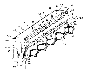
Referring initially to Fig. 1, a panel assembly 10
according to the present invention comprises a mounting
bracket 12, a bracket attachment 14, a bracket hinge 16, a
patch panel 18, a wire management panel 20, and a panel hinge
22. Pairs of selectively engageable fastening elements or
screws 24, 26, 28, and 30 connect the panels 18 and 20 to the
bracket hinge 16 and the bracket attachment 14. The
engagement or disengagement of fastening elements 24 and 26
219~6~2
_ _ 6 _
and 30 with the bracket hinge and the bracket attachment will
determine the ability of the patch panel 18 to fold down and
the ability of both panels 18 and 20 to pivot open. As
illustrated in Fig. 9, multiport adapters 23 are affixed to
the patch panel 18 for the wire terminations.
As seen in Fig. 1, mounting bracket 12 has a base member
40, a first side member 42 and a second side member 44. The
base member 40 extends between and is perpendicular to the
side members 42 and 44. Also, the base member 40 has support
means in the form of holes 46 for mounting the bracket 12 on a
wall (not shown). Although holes 46 are shown as circular
openings with slots, any suitable supporting device can be
attached to or incorporated in the bracket for mounting the
bracket on a wall. Further, the holes 46 may be located in
any convenient location in the bracket 12.
The first side member 42, the second side member 44, and
the base member 40 each have a cable entry aperture 48, 50,
52, respectively. These apertures 48, 50 and 52 receive cable
into the bracket 12 and provide access to the adapters 23 on
the patch panel 18. Cable entry apertures 48, 50 and 52 are
positioned to enable the cable to enter the mounting bracket
at locations other than through the top 54 or the bottom 56 of
the bracket 12. Since the cable is not entering through the
top 54 or the bottom 56 of the bracket nor occupying the space
adjacent thereto, other panel assemblies 10 can be stacked
directly above or below the panel assembly 10. This stacking
feature is described in greater detail below.
~1976~2
.. - 7 -
As shown in Figs. 3-5 and 11, the second side member 44
has a reinforced threaded hole 58 for receiving a selectively
engageable fastener or screw 62 and for securing the bracket
attachment 14. Bracket attachment 14 is L-shaped. A first
end 60 of the bracket attachment 14 has a recess 61 (not
shown) that is sized and located to slidably receive screw 62.
When the screw 62 is loosened, the connection between the
recess 61 and the screw 62 is such that the bracket attachment
14 can be slidably removed from the bracket 12. Disengagement
of the bracket attachment 14 in this manner allows for
simplified detaching and swinging of the panels 18 and 20 to
an open position. When the screw 62 is tightly secured within
the recess 61 in the first end 60 of the bracket attachment 14
and the hole 58, the bracket attachment 14 is securely affixed
to the second side member 44 of the mounting bracket 12.
Second end 63 of the bracket attachment 14 is
perpendicular to the first end 60 and has a first pair of
reinforced internally threaded holes 65 for receiving screws
26, and a second pair of reinforced internally threaded holes
68 for receiving screws 30. The bracket attachment 14 is
approximately one quarter of an inch shorter than the height
of the second side member 44 to allow for stacking of multiple
panel assemblies 10.
As seen in Figs. 1, 3 and 5, bracket hinge 16 has a first
half 70 and a second half 72. The first half 70 of the
bracket hinge 16 is attached to first side member 42 by spot
welding, or alternatively, by any conventional method of
fastening. The second half 72 of the bracket hinge 16 has two
2197632
,__ _8_
pairs of reinforced threaded holes 74 and 76. The first pair
of reinforced threaded holes 74 is located above the second
pair of holes 76 to receive screws 24 When attached to one end
of the patch panel 18. The second pair of holes 76 receives
screws 26 to attach to the hinged end of wire management panel
20.
As seen in Figs. 1, 2, 4 and 6, the two halves 70 and 72
pivot relative to each other about pivot axis 78. Patch panel
18 and wire management panel 20 can pivot about pivot axis 78
when both panels 18 and 20 are attached to the bracket hinge
18. The panels 18 and 20 pivot from a closed position (Fig.
1) to an open position (Fig. 4 or 6), 180° from the closed
position. In the closed position, the ends of the panels 18
and 20 opposite the bracket hinge 16 engage the bracket
attachment 14.
Bracket hinge 16 is shorter in height than the first side
member 42, typically by one quarter inch. The height of
bracket hinge 16 is equivalent to the height of bracket
attachment 14. This enables stacking of multiple panel
assemblies 10.
Patch panel 18 is of conventional design. As seen in
Figs. 1, 3 and 5, patch panel 18 is rectangular and has two
pairs of slots 80 and 82, one pair at each end. Slots 80
receive screws 24 for selectively fastening the patch panel 18
to the bracket hinge 16. Slots 82 receive screws 26 for
selectively fastening to bracket attachment 14.
Patch panel 18 has upper and lower bent sections 84 and
86. The lower bent section 86 provides a surface for
. ~219763~
_ g _
attaching the panel hinges 22. Patch panel 18 also has
elongated, rectangular openings 88 for receiving multiport
adapters 23. The rectangular openings 88 are configured in a
conventional manner to receive six multiport adapters 23
resulting in 48 connection ports or jacks 132. Recessed
apertures 90 are located adjacent each rectangular opening 88
for receiving fasteners 138 associated with the multiport
adapter 23 for securing the multiport adapter 23 to the patch
panel 18. As seen in Fig. 8, the front surface 92 of the
patch panel 18 includes indicia 96 for indicating the identity
of each jack 132. Although patch panel 18 has been disclosed
as having twelve openings 88 that receive six adapters, the
patch panel 18 may be altered to receive other types and
numbers of adapters.
Wire management panel 20 has a pair of slots 104. Slots
102 selectively receive screws 28 for connecting wire
management panel 20 to the lower half of the bracket hinge 16.
A pair of similar slots (not shown) are located at the
opposite end of the wire management panel 20 and receive
screws 30 for connecting the wire management panel to the
lower half of the bracket attachment 14.
Wire management panel 20 also has upper and lower bent
sections 106 and 108. Lower bent section 108 extends in a
continuous fashion, whereas upper bent section 106 has two
openings 110. Openings 110 enable panel hinges 22 to be
attached to the rear surface 112 of the wire management panel
20.
~'~~~2
- 10 -
The front surface 114 of the wire management panel 20 has
five wire holders 116. Each wire holder 116 is a five-bend
metal wire ring connected to the front surface 114 by welding,
rivets, screws, or other conventional means. The holders 116
prevent entanglement of patch cables.
Panel hinges 22 pivotally secure the patch panel 18 to
the wire management panel 20. A first half 120 of each panel
hinge 22 is welded or otherwise connected to the rear surface
112 of the wire management panel 20. A second half 122 of
each panel hinge 22 is secured to the lower bent section 86 of
patch panel 18 by screws 124 and nuts 126, or alternatively,
in any conventional manner.
The two halves 120 and 122 of the panel hinges 22 join to
form a second pivot axis 128. Pivot axis 128 is perpendicular
to first pivot axis 78 and enables the patch panel 18 to pivot
from the closed position shown in Fig. 1 down to an open
position shown in Figs. 2 and 3. Panel hinges 22 have
sufficient freedom of rotation to enable the patch panel 18 to
rotate down until it contacts wire holders 116. When the
patch panel 18 is rotated down as shown~in Fig. 2, the wire
holders 116 act as a bench that supports the patch panel 18
during the termination of wires to the multiport adapters 23.
Although two pivot panel hinges 22 are shown, a single panel
hinge 22 or more than two panel hinges 22 can also be used.
As seen in Figs. 8-10, multiport adapter 23 is a Category
5, 110-type multiport adapter. Since the adapter 23 for each
pair of openings 88 is substantially identical, only one
adapter 23 will be described in detail.
2i97s32
- 11 -
Adapter 23 has a front surface 130 with eight openings or
jacks 132 for receiving conventional plugs (not shown). The
front surface 130 is divided into a first half 134 and a
second half 136. Each half 134 and 136 is inserted into one
rectangular opening 88 and has four jacks 132. As best seen
in Fig. 8, the front surface 92 of the patch panel 18 is
marked numerically to indicate the identity of each jack 132.
Screws 138 typically fasten the adapter 23 to the rear
surface 94 of the patch panel. The screws 138 are received by
the recessed apertures 90. The rear portions 140 of the
adapters 23 have terminal extensions 142 which provide
connection points for wires (not shown) during the termination
process. The terminal extensions 142 are divided into ports
143. Each jack 132 has a respective port 143.
When the patch panel 18 is folded down as in Fig. 2, the
front surface 92 of the patch panel 18 is hidden from view,
and an installer cannot easily identify or distinguish
individual ports 143. Therefore, adhesive labels 144 are
attached to a protective covering 146 positioned over the rear
portion 140 of the adapter 23. Each label 144 contains
numerical indicia 148 that identifies each port 143. The
indicia 148 on the label 144 is identical to the indicia 96
that is located on the front surface 92 of the patch panel 18.
Although Category 110-type adapters 23 have been shown, the
patch panel 18 can be configured to receive other types of
adapters.
Fig. 1 shows the panel assembly 10 in its fully closed
position. Cable enters the panel assembly through one or more
219'~f ~2
- 12 -
of the cable entry apertures 48, 50 and 52. When an installer
needs to perform wire terminations on the adapters 23, the
rear portion 140 of the adapters 23 must be accessed. The
panel assembly 10 provides the installer with numerous options
for accessing the rear portion 140 of the adapters 23
depending upon how the panel assembly is situated, and the
space available for the installer to maneuver around the panel
assembly 10.
A first option for the installer is to pivot the patch
panel 18 from the closed position shown in Fig. 1 to the open
position shown.in Figs. 2 and 3. The installer removes the
selectively engageable fastener elements or screws 24 and 26
and pivots the patch panel 18 about the first pivot axis 78.
Although Fig. 1 shows both sets of screws 24 and 26 securing
the patch panel to the bracket 12, it should be understood
that only one selectively engageable fastening element,
located at the position of the uppermost screw 26 as shown in
Fig. 1, is needed to secure and release the patch panel 18 as
shown.
Once the patch panel 18 is in the open position shown in
Figs. 2 and 3, additional access to the patch panel 18 and the
interior of the mounting bracket 12 can be achieved. This
second option is achieved by swinging the wire management
panel 20, with the patch panel folded down on top of it, about
the pivot axis 78 as shown in Figs. 6 and 7. The installer
need only remove the screws 30 to free the wire management
panel 20 for pivoting as shown in Fig. 6.
2197s~~
- 13 -
If the installer selects not to fold down the patch panel
18 as described above, the patch panel 18 and the wire
management panel 20 can maintain their vertical, coplanar
orientation as shown in Fig. 1. This third option involves
pivoting both upright panels 18 and 20 to an open position
about pivot axis 78 as shown in Figs. 4 and 5. This pivoting
action is achieved by removing screws 26 and 30 from the patch
panel and the wire management panel, respectively. Screws 24
remain attached to bracket hinge 16 and maintain the patch
panel 18 in its upright position. Alternatively, screw 62 may
be loosened, and the bracket attachment 14 may be removed from
the bracket 12 along with the panels 18 and 20 to pivot the
panels 18 and 20 to the open position as shown in Figs. 4 and
5.
Although selectively engageable fastening elements 24,
26, 28, 30 and 62 are described as screws, any selectively
engageable fastening element may be used. For instance,
bayonet-type or snap-fit fasteners can be employed to simplify
opening and closing the panels 18 and 20. Also, although
multiple screws 24, 26, 28 and 30 are shown at each end of the
panels 18 and 20, a single fastener, or three or more
fasteners can be used depending upon the application. Still
further, since screws 28 attaching the wire management panel
20 to the hinge 16 are not removed for the opening positions
described above, fasteners 28 may be replaced with non-
selectively engageable fastening elements. For instance,
screws 28 may be replaced with spot welding. Finally,
although the panel assembly has been disclosed as pivoting
219~76~2
open in a clockwise direction when viewed from the top, the
panel assembly 10 may be configured such that the panels 18
and 20 pivot in a counter-clockwise direction. The pivot axis
78 and bracket hinge 16 would then be secured to second side
member 44.
The panel assembly 10 can be stacked on top of or below
other assemblies similar to panel assembly 10. This stacking
feature is possible since the cables entering the bracket 12
are not required to enter the bracket 12 through the top 54 or
bottom 56 of the bracket 12. The cables can enter the bracket
12 through the lateral or side cable entry apertures 48, 50
and 52. Also, the height of the panels 18 and 20, the bracket
hinge 16, and the bracket attachment 14 is less than the
height of the first and second side members 42 and 44 by
approximately one quarter inch. This establishes clearance
for an assembly 10 placed on top of bracket 12. Since the
upper bent section 84 of the patch panel 18 is spaced from the
top edge of the side members 42 and 44, the patch panel 18 is
free to swing open even if a second panel assembly 10 is
located on the base member upper surface 41 and the side
member upper surfaces 43 and 45.
All elements of the panel assembly 10 described are
preferably constructed from aluminum. However, other metals
and other materials with sufficient structural characteristics
can be used.
While a particular embodiment has been chosen to
illustrate the invention, it will be understood by those
skilled in the art that various changes and modifications can
219'~s~'~
- 15 -
be made therein without departing from the scope of the
invention as defined in the appended claims.