Note: Descriptions are shown in the official language in which they were submitted.
21 q7972
- EDITING APPARATUS AND EDITING METHOD
BACRGROUND OF THE INVENTION
The present invention relates to editing apparatus and
editing method using a disk-like recording medium.
Recently, there has been used an editing method in
which a video signal recorded on a magnetic tape or the like is
temporarilly recorded on a hard disk and only a video signal
located within a desired interval is reproduced from the video
signal recorded on the hard disk, whereafter the reproduced signal
is processed in a variety of fashions. The reason for this is
that access speed of the hard disk is remarkably higher than that
of the magnetic tape.
By the way, the hard disk has a high access speed but its
storage capacity is very smaller than that of the magnetic tape.
Therefore, in an editing method using a hard disk, it is
preferable that only a video signal used in the edition is
recorded so as to effectively use the hard disk small in the
storage capacity. However, it is difficult for an operator that a
video signal reproduced from the magnetic tape is monitored on the
picture screen of a television monitor, a head position and an end
position of an interval desired to be used are positively
designated by a key input and then it is recorded on the hard
2 1 q7972
disk. Also, this work is difficult due to the function of
equipments.
OBJECT AND SUMMARY OF THE I-Nv~NllON
It is therefore an object of the present invention to
provide editing apparatus and editing method in which a storage
capacity of a disk-like recording medium can be used effectively
and in which a video signal necessary for editing can be reliably
transferred from a tape-like recording medium to a disk-like
recording medium.
An editing apparatus which attains a main object of the
present invention comprises reproducing means for reproducing a
video signal recorded in a tape-like recording medium, recording
means for recording a reproduced video signal in a disk-like
recording medium, input means for designating a recording starting
pointing and a recording ending point; and control means for
controlling an operation of the recording means based on an output
signal from the input means, in which the control means controls
the recording means such that the video signal reproduced by the
reproducing means is repeatedly recorded on a predetermined
repetitive recording area of the disk-like recording medium until
data indicative of the recording starting position is supplied
thereto through the input means after start of operation, the
control means controls the recording means such that the video
21 g7972
signal reproduced by the reproducing means is sequentially
recorded on a predetermined normal recording area of the disk-like
recording medium when data indicative of the recording starting
point is supplied thereto through the input means, and the control
means controls the recording means such that the video signal
reproduced by the reproducing means is repeatedly recorded on a
second predetermined repetitive recording area of the disk-like
recording medium when data indicative of the recording ending
point is supplied thereto through the input means.
An editing method which attains a main object of the present
invention comprises steps of reproducing a video signal stored a
tape-like recording medium, designating a recording starting
point; repeatedly recording the video signal on a predetermined
repetitive recording area of a disk-like recording medium until
the recording starting point is designated, sequentially recording
the video signal on a predetermined normal recording area of the
disk-like recording medium when the recording starting point is
designated, and recording the video signal on the normal recording
area during a predetermined period when a recording ending point
is designated, and then repetitively recording the video signal on
a second predetermined repetitive recording area of the disk-like
recording medium.
BRIEF DESCRIPTION OF THE DRAWINGS
2 1 97972
- FIGS. lA through lC are explanatory diagrams showing a
concept of editing apparatus according to the present invention;
FIG. 2 iS a block diagram showing an editing apparatus
according to an embodiment of the present invention;
FIG. 3A iS a schematic diagram showing an editing
table used in the editing apparatus shown in FIG. 2;
FIGS. 3B through 3E are schematic diagrams used to
explain an operation of the editing apparatus shown in FIG. 2;
FIG. 4 iS a schematic diagram used to explain an
operation of the editing apparatus shown in FIG. 2; and
FIGS. 5 and 6 are flowcharts to which reference will
be made in explaining an operation of the editing apparatus shown
in FIG. 2.
DETAILED DESCRIPTION OF THE PREFERRED EMBODIMENTS
The present invention will now be described in detail
below with reference to FIGS. lA through 6.
FIGS. lA through lC are diagrams used to explain a
concept of an editing apparatus according to the present
invention.
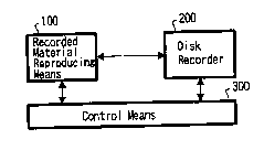
As shown in FIG. lA, the editing apparatus includes a
material reproducing means 100, a disk recorder 200 and a control
means 300. A material that is reproduced by the material
reproducing means 100 is recorded on the disk recorder 200.
~1 97~ 72
- The manner in which the material reproduced by the
material reproducing means 100 is recorded on the disk recorder
200 will be described with reference to FIGS. lB and lC.
FIG. lB shows the manner in which materials recorded
on a recording medium such as a tape-like recording medium or the
like are reproduced by the material reproducing means 100. As
shown in FIG. lB, when cue-ins and cue-outs are respectively
designated, materials between respective pairs of the cue-in and
the cue-out are provided as materials A, B, C. FIG. lC
conceptually shows the manner in which materials are recorded on
recording areas of the disk recorder 200. In FIG. lC, areas shown
hatched illustrate repetitive recording areas, and areas shown
dots illustrate extra recording areas, respectively.
As shown in FIG. lA, materials are incessantly
reproduced by the material reproducing means 100. Reproduced
materials are repeatedly recorded in the disk recording areas at
its repetitive recording areas until a cue-in is designated.
Sectors 1 to 5 are recording areas and reproduced materials are
recorded in the sectors 1, 2, ..., 5, in that order. After
reproduced material has been recorded in the sector 5, reproduced
materials are recorded one more time in the sequential order of
the sectors 1, 2, ..., 5. During reproduced materials are
repeatedly recorded in the repetitive recording areas, if a cue-in
2 1 9~972
is designated, then a seek operation is started immediately and
reproduced materials are sequentially recorded in the next areas
of the repetitive recording areas. At that time, the above-
mentioned repetitive recording is not carried out and the ordinary
recording is carried out.
Subsequently, when a cue-out is designated, the
repetitive recording area of the same duration of time is set from
a recording area obtained at the time a predetermined time is
passed from the cue-out. Reproduced materials are repetitively
recorded in the repetitive recording areas. When the "
predetermined time" has passed, as shown by dots in FIG. lC, the
extra recording areas are formed. When the above-mentioned
processing is carried out repeatedly, materials A, B, C each of
which has extra portions attached to the starting and ending
portions, are recorded on the recording areas of the disk.
Hence, necessary materials can be recorded on the disk
reliably and the small storage capacity can be used effectively.
The present invention will be described below more fully with
reference to FIG. 2 and the following sheets of drawings.
FIG. 2 is a block diagram showing an editing system
according to an embodiment of the present invention.
In the editing system shown in FIG. 2, a CPU (central
processing unit) bus 304 is connected to a CPU 303, and a VCR
21 97972
(video cassette recorder) 101 is connected to the CPU bus 304
through an interface (IF) circuit 102. An editor 301 is connected
through an interface circuit 302 to the bus 304 to which a RAM
(random-access memory) 306, a video control unit 311 and a disk
recorder control unit 312 are also connected. Hard disk drives 201
through 207 are connected to the disk recorder control unit 312 in
a daisy chain fashion, and a video control unit 311 and the disk
recorder control unit 312 are connected to a data bus 305.
The RAM 306 stores therein recording mode data 307,
starting position data 308, ending position data 309 and present
position data 310 which will be described later on. The disk
recorder control unit 312 comprises an image buffer 313 serving as
a buffer for data to be stored on or data reproduced from the disk
drives 201 through 207 and a disk control unit 315. A storage
capacity of the image buffer 313 is selected to be sufficient so
that at least reproduced video data, which are incessantly
supplied from the VCR 101, can be all recorded in the disk drives
201 through 207.
The disk control unit 314 includes a table 315 to
control the disk drives 201 through 207. The table 315 will be
described below with reference to FIG. 3A. As shown in FIG. 3A,
the table 315 comprises block number data, logical address data
and disk ID (identification) data. The block number data is given
2 1 ~7q72
to each of video data of one frame upon recording. The logical
address data comprises track number data, logical sector number
data and data length data. The disk ID data is each ID
of the hard disk drives 201 through 207. The present position
data 310 shown in FIG. 2 corresponds to logical address data.
The logical sector number data corresponds to a
starting sector number of all sectors corresponding to the data
amount of video data of one frame. Video data is data of frame
unit and recorded in the sector unit. One frame generally
comprises N sectors so that block number data corresponding to
each frame is registered in the table 315 in correspondence with
starting logical sector number data of sectors of each frame.
Thus, when block number data is supplied from the CPU 303, the
disk control unit 314 supplies logical address data, which is
registered in correspondence with that block number data, to the
hard disk drives 201 through 207. When supplied with the logical
address data, the hard disk drive 201 converts the thus supplied
logical address data into physical address data, and reads out
video data from the recording area indicated by the physical
address data by an amount shown by data length data.
Data length data always becomes a constant value
because the m;n;mllm unit of recording and playback is one frame.
The contents of the table 315 are rewritten in the same manner as
2 1 97972
the-manner in which video data reproduced from the VCR 101 is
recorded in the hard disk drives 201 through 207. Specifically,
within the range of logical address data corresponding to the
repetitive recording area, block number data generated from the
CPU 303 are rewritten cyclically. Then, when a mark-in key 350 is
depressed, block number data and logical address data are
sequentially written in the next storage area of the range of the
logical address corresponding to the repetitive recording area.
Logical address data may, of course, be loaded into the RAM 306
from a ROM (read-only memory) or the like, not shown, and only
block number data may be rewritten.
The recording sequence will be described with
reference to FIG. 4. If a start key 351 of the editor 301 shown
in FIG. 2 is depressed, then the editor 301 supplies a control
signal indicative of the repetitive recording to be carried out to
the CPU 303. Thus, the CPU 303 places the disk control unit 314
in the repetitive recording mode. The disk control unit 314
controls the hard disk drives 201 through 207 in such a manner
that reproduced video data supplied from the VCR 101 through the
video control unit 311 are repetitively recorded in recording
areas of 30 blocks of the hard disk drives 201 through 207.
Watching reproduced video data displayed on a display 353 after it
has been supplied to the editor 301 from the video control unit
21 97972
311-through the data bus 305, the operator determines the cue-in
and the cue-out of the reproduced video data.
If the operator depresses the mark-in key 350 of the
editor 301 shown in FIG. 2 at the arrival of a desired cue-in,
then the editor 301 supplies a control signal indicative of the
normal recording to be carried out to the CPU 303 so that the CPU
303 places the disk control unit 314 in the normal recording mode.
Then, the disk control unit 314 controls the hard disk drives 201
through 207 in such a fashion that reproduced video data supplied
from the VCR 101 through the video control unit 311 is
successively recorded in the next area of recording areas of 30
blocks of the hard disk drives 201 through 207. The mark-in key
350 is used to designate a cue-in.
Subsequently, if the operator depresses a mark-out key
352 of the editor 301 shown in FIG. 2 at the arrival of a desired
cue-out, then the editor 301 supplies a control signal indicative
of the repetitive recording to be carried out with a delay of 30
blocks, for example, to the CPU 303 so that the CPu 303 sets the
disk control unit 314 in the extra recording mode. In the extra
recording mode, after depression of the mark-out key 352, video
data of 30 blocks are recorded in surplus and then the disk
control unit 314 goes to the repetitive recording mode. The disk
control unit 314 controls the hard disk drives 201 through 207 in
2 1 97q72
such a manner that reproduced video data supplied from the VCR 101
through the video control unit 311 are recorded on the recording
areas of 30 blocks of the hard disk drives 201 through 207. The
mark-out key 352 is used to designate cue-out.
After the recording of video data on the recording
areas of 30 block has been finished, the disk control unit 314 is
placed again in the repetitive recording mode. Therefore, if the
above-mentioned processing is repeated, materials will be
sequentially recorded in the hard disk drives 201 through 207.
FIGS. 3B through 3E are diagrams showing the
repetitive recording more clearly. In the repetitive recording,
materials 1, 2, 3, ..., 6 are sequentially recorded in the
repetitive recording areas of the hard disk drives 201 through 207
in the order in which the materials 1, 2, 3, ..., 6 are supplied.
If materials up to the material 6 are recorded, then the next
material 7 is recorded again in the starting portion of the
repetitive recording area as shown in FIG. 3C. Then, as shown in
FIG. 3D, the next material 8 is recorded during the next cycle.
If the above-mentioned processing is repeated, then materials 7,
8, 9 and 10 are recorded as shown in FIG. 3E.
In this state, if the operator depresses the mark-in
key 350, then under control of the disk control unit 314, areas of
the hard disk drives 201 through 207 in which the materials 4 and
21 97972
6 are recorded are extracted by the seek operation and the next
recording area of the repetitive recording area is accessed. The
repetitive recording mode for the repetitive recording area will
be released from now on. Then, materials 11, 12 supplied after
the material 10 are sequentially recorded.
The manner in which materials recorded on the hard
disk drives 201 through 207 are reproduced will be described
below. Specifically, reproduced video data are temporarily
written in the image buffer 313, then read out therefrom and
supplied through the data bus 305 to the video control unit 311,
whereafter it is converted into a video signal and then outputted
from an output terminal 311a. Moreover, the reproduced video
data is supplied through the data bus 305 to the editor 301 and
then displayed by the display 353.
The manner in which the editing system shown in FIG. 2
is operated upon recording will be described with reference to
FIGS. 5 and 6.
Referring to FIG. 5, following the start of operation,
it is determined at a decision step Sl by the CPU 303 shown in
FIG. 2 whether or not data is entered by operation keys of the
editor 301. If a YES is outputted at the decision step Sl, then
control goes to the next decision step S2. In the decision step
S2, it is determined by the CPu 303 shown in FIG. 2 whether or not
21 q797~
the-start key 351 of the editor 301 is depressed. If a YES is
outputted at the decision step S2, then it is determined that the
repetitive recording is instructed. Then, control goes to the
next decision step S3. When the start key 351 is depressed, data
indicating the repetitive recording to be carried out is stored in
the RAM 306 as the recording mode data 307. It is determined by
the CPU 303 by reading the recording mode data 307 whether or not
the recording mode is the repetitive recording mode.
As a consequence, the CPU 303 shown in FIG. 2 supplies
a playback start command to the video control unit 311. The video
control unit 311 supplies a playback start command to the VCR 101
through the interface circuit 102. Reproduced video data from
the VCR 101 is sequentially written in the image buffer 313 of the
disk recorder control unit 312 through the video control unit 311
and the data bus 305.
In the decision step S3, it is determined by the CPU
303 shown in FIG. 2 whether or not pres~nt position data is larger
than ending position data. If a YES is outputted at the decision
step S3, then control goes to a step S4. If a NO is outputted at
the decision step S3, then control goes to a step S5. When a
power switch of the editing system is turned on, under control of
the CPU 303, the starting position data 308 and the ending
position data 309 are stored in the RAM 306 and starting logical
2 1 97~72
address data is stored in the RAM 306 as the present position data
310. The ending position data 309 shows the position advanced
from the starting position data 308 by 30 blocks.
In the step S4, the starting position data 308 is
written in the storage area of the present position data 310 on
the storage area of the RAM 306 under control of the CPU 303 shown
in FIG. 2 because the position shown by the present position data
310 exceeds the position shown by the ending position data 309.
In order to effect the repetitive recording, the starting position
data 308 should be stored when the position shown by the present
position data 310 reaches the position shown by the ending
position data 309.
In the step S5, the CPU 303 shown in FIG. 2 reads out
the present position data 310 stored in the RAM 306 and supplies
the above present position data 310 to the disk recorder control
unit 312. The disk control unit 314 of the disk recorder control
unit 312 determines the hard disk drives 201 through 207 to which
video data is transferred. The disk control unit 314 reads out
physical address data corresponding to the present position data
310 supplied from the CPU 303 from the table 315.
Subsequently, the disk control unit 314 reads video
data of one block from the image buffer 313, and transfers the
video data of one block to the hard disk drives 201 through 207
14
21 ~7~72
together with the physical address data.
The video data of one block transferred to the hard
disk drives 201 through 207 is recorded on the hard disk drives
201 through 207 at their recording areas shown by the physical
address data. Further, the disk control unit 314 registers disk
ID data indicative of the hard disk drives 201 to 207 to which
the video data is transferred in the table 315.
In the next step S6, the CPU 303 shown in FIG. 2
increments the value of the present position data 310 stored in
the RAM 306 by one block.
In the next decision step S7, it is determined by the
CPU 303 whether or not the mark-in key 350 is depressed. If a YES
is outputted at the decision step S7, then control goes to a step
S8. If on the other hand a NO is outputted at the decision step
S7, then control goes back to the decision step S3.
At the step S8, the CPu 303 shown in FIG. 2 increments
the value of the ending position data 309 stored in the RAM 306 by
one block.
As shown in FIG. 6, in the next step S9, the CPU 303
shown in FIG. 2 writes the ending position data 309 stored in the
RAM 306 in the RAM 306 at its storage area in which the present
position data 310 is stored.
In the next step S10, the CPU 303 shown in FIG. 2
2 1 9 79 72
reads out the present position data 310 stored in the RAM 306, and
supplies the above present position data 310 to the disk recorder
control unit 312. The disk control unit 314 in the disk recorder
control unit 312 determines the hard disk drives 201 through 207
to which video data is transferred. The disk control unit 314
reads out physical address data corresponding to the present
position data 310 supplied from the CPU 303 from the table 315.
Subsequently, the disk control unit 314 reads out video data of
one block from the image buffer 313 and transfers the video data
of one block to the hard disk drives 201 through 207 together with
the physical address data.
The video data of one block transferred to the hard
disk drives 201 through 207 is recorded in the hard disk drives
201 through 207 at their recording areas shown by the physical
address data. Further, the disk control unit 314 registers disk
ID data of the hard disk drives 201 through 207 to which the video
data is transferred in the table 315.
In the next step S11, the CPU 303 shown in FIG. 2
increments the value of the present position data 310 stored in
the RAM 306 by one block.
In the next decision step S12, it is determined by the
CPU 303 shown in FIG. 2 whether or not the end key 354 of the
editor 301 is depressed. If a YES is outputted at the decision
16
2197972
step S12, control is ended. If on the other hand a NO is
outputted, then control goes to the next decision step S13.
At the decision step S13, it is determined by the CPU
303 shown in FIG. 2 whether or not the mark-out key 352 of the
editor 301 is depressed. If a YES is outputted at the decision
step S13, then control goes to the next decision step S14. If on
the other hand a NO is outputted at the decision step S13, then
control goes back to the step S10.
In the decision step S14, it is determined by the CPU
303 shown in FIG. 2 whether or not the present position data is
larger than the ending position data. If a YES is outputted at
the decision step S14, then control is ended. If on the other
hand a NO is outputted, then control goes to a step S15.
In the step S15, the CPU 303 shown in FIG. 2 writes
the starting position data 308 in the RAM 306 at its storage area
in which the present position data 310 is stored. The reason for
this has already been described with reference to the step S4.
In the next step S16, the CPU 303 shown in FIG. 2
reads out the present position data 310 stored in the RAM 306, and
supplied the above present position data 310 to the disk recorder
control unit 312. The disk control unit 314 in the disk recorder
control unit 312 determines the hard disk drives 201 through 207
to which video data is transferred. The disk control unit 314
2 1 97972
reads out physical address data corresponding to the present
position data 310 supplied from the CPU 303 from the table 315.
Subsequently, the disk control unit 314 reads out the video data
of one block from the image buffer 313 and transfers the above
video data of one block to the hard disk drives 201 through 207
together with the physical address data.
The video data of one block transferred to the hard
disk drives 201 to 207 is recorded in the hard disk drives at
their recording areas shown by the physical address data.
Further, the disk control unit 314 registers disk ID data of the
hard disk drives 201 through 207 to which the video data was
transferred in the table 315.
In the next step S17, the CPU 303 shown in FIG. 2
increments the value of the present position data 310 stored in
the RAM 306 by one block. Then, control goes back to the decision
step S14.
Upon reproduction, the editor 301 can vary the cue-in
and cue-out by entering block number data through a data input
device 356. In the editor 301, cue-in and cue-out are designated
by block number data and a playback key 355 is depressed. With
reference to the table 315 shown in FIG. 2, the CPU 303
sequentially supplies logical address data corresponding to block
number data from the block number data of the designated cue-in to
2 1 97972
the-block number data of the designated cue-out to the hard disk
drives 201 through 207 and places the hard disk drives 201 through
207 in the reproducing mode. Therefore, video data ranging from
the designated cue-in to the designated cue-out are reproduced
from the hard disk drives 201 through 207. Thus, even when the
operator depresses the mark-in key 350 and the mark-out key 352 at
different timings, the operator can change desired cue-in and cue-
out easily.
As described above, when the value shown by the
present position data 310 is larger than that shown by the ending
position data 309, the starting position data 308 is written in
the RAM 306 at its storage area in which the present position data
310 is stored, and the present position data 310 is used as
recording address for the hard disk drives 201 through 207. Thus,
video data reproduced by the VCR 101 can be recorded in the disk
drives 201 through 207 at their recording areas of predetermined
30 blocks in the repetitive recording mode.
If the mark-in key 350 is depressed during the
repetitive recording is carried out, then the normal recording is
started from the next area of the predetermined recording area of
30 blocks.
Then, if the mark-out key 352 is depressed, the
repetitive recording is carried out again after a time period of
19
21 97~72
30 blocks was elapsed from that time point, i.e. after video data
of 30 blocks has been recorded.
Therefore, the operator can set a desired position to
the cue-in or cue-out reliably. Specifically, when the operator
designates a cue-in and a cue-out in a manual fashion, it is
unavoidable that the designated positions are delayed from desired
cue-in and desired cue-out. However, video data are recorded in
the recording area of 30 blocks from the position immediately-
preceding the cue-in and the recording area of 30 blocks from the
position ;~ tely-succeeding the cue-out. Accordingly, even
when the designated position is delayed from a desired cue-in or a
desired cue-out, video data at that position are recorded in the
above-mentioned recording areas. Thus, it is sufficient for the
operator to advance or delay the positions of the cue-in and the
cue-out in the later stage.
Furthermore, there is the large advantage that the
storage capacities of the hard disk drives 201 through 2007 and
the number of the hard disk drives 201 through 207 can be
~;n;~; ~ed.
As described above, reproduced materials are
repeatedly recorded in the repetitive recording areas of the
recordable areas of the disk recorder until the cue-in is
designated. When the cue-in is designated, the reproduced
21 97972
materials are recorded in the normal recording areas of the disk
recorder in the normal recording mode. After the cue-out is
designated, the reproduced materials are repeatedly recorded in
the above repetitive recording areas after a predetermined time
has elapsed since cue-out was designated. Thus, the recording
areas of the disk-like recording medium can be used effectively,
and desired materials of the materials recorded in the tape-like
recording medium can be reliably recorded in the disk-like
recording medium.
Having described a preferred embodiment of the
invention with reference to the accompanying drawings, it is to be
understood that the present invention is not limited to that
precise embodiment and that various changes and modifications
could be effected therein by one skilled in the art without
departing from the spirit or scope of the invention as defined in
the appended claims.