Language selection

Search

Patent 2198220 Summary

Third-party information liability

Some of the information on this Web page has been provided by external sources. The Government of Canada is not responsible for the accuracy, reliability or currency of the information supplied by external sources. Users wishing to rely upon this information should consult directly with the source of the information. Content provided by external sources is not subject to official languages, privacy and accessibility requirements.

Claims and Abstract availability

Any discrepancies in the text and image of the Claims and Abstract are due to differing posting times. Text of the Claims and Abstract are posted:

  • At the time the application is open to public inspection;
  • At the time of issue of the patent (grant).
(12) Patent Application: (11) CA 2198220
(54) English Title: A MATERIAL DISPENSING APPARATUS
(54) French Title: DISTRIBUTEUR DE MATERIAUX A FINES PARTICULES
Status: Deemed Abandoned and Beyond the Period of Reinstatement - Pending Response to Notice of Disregarded Communication
Bibliographic Data
(51) International Patent Classification (IPC):
  • G03G 15/08 (2006.01)
(72) Inventors :
  • RANKIN, WILLIAM (Ireland)
(73) Owners :
  • FAIRCOVE SYSTEMS
(71) Applicants :
  • FAIRCOVE SYSTEMS (Ireland)
(74) Agent: MARKS & CLERK
(74) Associate agent:
(45) Issued:
(86) PCT Filing Date: 1995-08-23
(87) Open to Public Inspection: 1996-02-29
Examination requested: 2000-02-23
Availability of licence: N/A
Dedicated to the Public: N/A
(25) Language of filing: English

Patent Cooperation Treaty (PCT): Yes
(86) PCT Filing Number: PCT/IE1995/000043
(87) International Publication Number: IE1995000043
(85) National Entry: 1997-02-21

(30) Application Priority Data:
Application No. Country/Territory Date
S940660 (Ireland) 1994-08-23

Abstracts

English Abstract


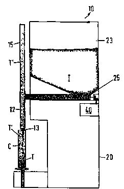
An apparatus for dispensing fine particulate material comprises a hopper (23)
for storing material (T) to be dispensed, a discharge tube (12) having a
discharge nozzle (13) and feeding means comprising an auger (25) for
transferring stored material (T) from the hopper (23) to the discharge tube
(12). The fine particulate material is regulated by a metering means (35)
which meters the amount transferred by the auger (25) to the discharge tube
(12). Material (T) is transferred to a container (C) to be charged by
positioning it against the discharge nozzle so that the auger (25) transfers a
predetermined amount of material (T) from the hopper (23) to the discharge
tube (12). Material laden displaced air (T') from the container (C) escapes
into a settling tube (15) where the material in the displaced air (T') is
allowed to settle and fall by gravity into the container (C).


French Abstract

Un appareil distributeur de matière sous forme de fines particules comprend une trémie (23) pour le stockage de la matière (T) à distribuer, un tube d'évacuation (12) pourvu d'une buse d'éjection (13) et des moyens d'alimentation comprenant une vis (25) destinée au transfert de la matière stockée (T) de la trémie (23) au tube d'évacuation (12). La matière en particules fines est régulée par un moyen de dosage (35) qui dose la quantité transférée par la vis (25) dans le tube d'évacuation (12). La matière (T) est transférée dans un récipient (C) que l'on charge en plaçant celui-ci contre la buse d'évacuation de telle sorte que la vis (25) transfère une quantité prédéterminée de matière (T) de la trémie (23) au tube d'évacuation (12). L'air déplacé (T'), chargé de matière, qui provient du récipient (C) s'échappe dans un tube de dépôt (15) dans lequel la matière présente dans l'air déplacé (T') peut se déposer et tomber par gravité dans le récipient (C).

Claims

Note: Claims are shown in the official language in which they were submitted.

- 7 -
CLAIMS:
1. An apparatus (10) for dispensing fine particulate
material (T) comprising:
a hopper (23) for storing material (T) to be
dispensed;
a discharge tube (12) having a discharge nozzle (13);
a generally horizontally disposed feeding means (25)
for transferring stored material (T) from the hopper to
the discharge tube (12);
a fine particulate material metering means (35) for
regulating the amount of material (T) transferred by the
feeding means (25) to the discharge tube (12);
a settling tube (15); and
biasing means operable to urge a container (C) to be
charged with material (T) into sealing engagement with
the discharge nozzle,
whereby in use the container (C) is sealed against the
discharge nozzle (13), the feeding means (25) transfers a
predetermined amount of material (T) from the hopper (25)
to the discharge tube (12) and material laden displaced air
(T') from the container (C) escapes into the settling tube
(15) where the material in the displaced air (T') settles
and falls by gravity into the container (C).
2. A dispensing apparatus as claimed in claim 1, in which
the feeding means comprises a generally horizontally
disposed auger (25).
3. A dispensing apparatus as claimed in claim 2, in which
the auger (25) is arranged so that the particulate material
(T) carried therethrough is biased to remain in the auger
(25) or to return to the hopper (23), whereby flow of the

- 8 -
material (T) ceases when the auger (25) stops.
4. A dispensing apparatus as claimed in either claim 2 or
claim 3, in which the metering means (35) comprises a timer
based switching means to regulate the number of revolutions
of the auger (25) so that the material through-feed is
accurately and consistently metered.
5. A dispensing apparatus as claimed in any one of claims
2 to 4, in which the discharge tube (12) and the settling
tube (15) form part of a vertically disposed tube which is
fed by the auger (25) at a junction located remote from the
tube's upper end.
6. A dispensing apparatus as claimed in any one of the
preceding claims, in which the container (C) is sealed
against the discharge nozzle (13) by a plate (30) having the
biasing means.
7. A dispensing apparatus as claimed in any one of the
preceding claims, in which the discharge nozzle (13) has a
tapered profile to facilitate sealing engagement with a
range of container charging apertures.
8. A dispensing apparatus as claimed in any one of the
preceding claims, which includes a means for agitating
the material (T) in the hopper (23).
9. A dispensing apparatus as claimed in claim 8, in which
the agitating means is driven from the feeding means (25).
10. A dispensing apparatus as claimed in any one of the
preceding claims, comprising a single hopper (23) and a
plurality of feeding means (25) and associated discharge
tubes (12).

Description

Note: Descriptions are shown in the official language in which they were submitted.


2 t ~220
.
A ~ATERIAL 3ISPENSING APPARATUS
The present invention relates to a dispensing apparatus and
more particularly relates to an apparatus for dispensing
fine particulate material such as toner for photocopiers
and laser printers. "Toner" is a term used in
re~loyLaphics to describe the electrostatic compound that
acts as the "ink" forming the image on a plain-paper copy.
Fine particulate material is known to be difficult to
handle in automated processes. This is particularly true
where the material is to be passed from one container to
another. Where material is passed from one container to
another, displaced air carries with it a certain amount of
the fine material. This arrangement is often
unsatisfactory as it creates a particle-laden atmosphere
which may be hazardous to breathe. Additionally,
accumulated material may affect machinery and may be
difficult to clean.
In a known semi-automated process such as that exemplified
by Per-Fil apparatus (Per-Fil Industries, Inc., Riverside,
New Jersey 08075, U.S.A.~, fine particulate material is
dispensed from a storage hopper into cartridges for use.
The material is toner for laser printers, photocopiers and
the like, and is used for charging cartridges which fit
specific ~rh;n~s. The dispensing apparatus is re~uired to
meter out a predetermined amount of toner into a range of
sizes of toner cartridge and comprises a hopper, a
vertically disposed auger and a dispensing noz21e. In this
filling process, the empty cartridge is held under the
dispensing nozzle and the auger is turned a preset number of
revolutions to feed the required amount of material to the
nozzle. The displaced air carries with it a quantity of
toner. Additionally, due to the liquid-like flow of fine
SI IEET

z ~
particulate material, the amount of toner dispensed from
the auger may vary unacceptably.
It is a object of the present invention to seek to
alleviate the above disadvantages and to provide an
improved dispensing apparatus for fine particulate material
such as toner.
Accordingly, the present invention provides an apparatus
for dispensing fine particulate material comprising:
a hopper for storing material to be dispensed;
a discharge tube having a discharge nozzle;
a generally horizontallv disposed feeding means for
transferring stored material from the hopper to the
discharge tube;
a fine particulate material metering means for
regulating the amount of material transferred by the
feeding means to the discharge tube;
a settling tube; and
biasing means operable to urge a container to be
charged with material into sealing engagement with the
discharge nozzle,
whereby in use the container is sealed against the discharge
nozzle, the feeding means transfers a predetermined amount
of material from the hopper to the discharge tube and
material laden displaced air from the container escapes into
the settling tube where the material in the displaced air
settles and falls by gravity into the container.
Preferably, the feeding means comprlses a generally
horizontally disposed auger.
Advantageously, the auger is arranged so that the
',~ S~
,~ . .

J 2 1 ~22~
-- 3 --
particulate material carried therethrough is biased to
remain in the auger or to return to the hopper, whereby flow
of the material ceases when the auger stops.
Conveniently, the metering means comprises a timer based
switching means to regulate the number of revolutions of the
auger so that the material through-feed is accurately and
consistently metered.
In a preferred embodiment, the discharge tube and the
settling tube form part of a vertically disposed tube which
is fed by the auger at a junction located remote from the
tube's upper end. The material falls from the junction
to the discharge nozzle at the lower end of the tube and
displaced air escapes upwardly via the discharge tube to the
settling tube where the material carried by the displaced
air is allowed to settle and fall under gravity into the
container juxtaposed the discharge nozzle.
Advantageously, the container is sealed against the
discharge nozzle by a plate having the biasing means
Conveniently, the discharge nozzle has a tapered profile to
facilitate sealing engagement with a range of container
charging apertures.
Preferably, a means is included for agitating the material
in the hopper.
Advantageously, the agitating means is driven from the
feeding means.
The apparatus preferably comprises a single hopper (23) and
a plurality of feeding means (25) and associated discharge
~ i-u jn~t~
_ _ _ _ _ _ _ _, , . . . . . , . _ , ... . , .. , . ,, _ _ _

wo s6~63as 2 ~ a ~ ~ 2 ~ r~ 't ~l3
~ - 4 -
tubes.
The invention will now be described more particularly with
reference to the accompanying drawings which show, by way
5 of example only, one o~ho~ir t of dispensing apparatus
according to the invention. In the drawings:
Figure 1 is a front elevation of the ~;Cpenc;ng apparatus;
10 Figure 2 is a side elevation of the dispensing apparatus;
and
Figure 3 is a sectional side elevation of the apparatus
taken along lines III - III of Figure 1.
Referring to the drawings and initially to Figures 1 and 2,
a dispensing apparatus 10 has two dispensing outlets each
comprising a dispensing tube 12 having a dispensing nozzle
13 thereon. Above each ~icrOnc; ng tube 12 is a settling
20 tube 15 which is open-ended to allow air to escape.
The apparatus 1Q further comprises a housing 20 which
contains a hopper 23 and an auger 25 for each dispensing
outlet, as shown in detail in Figure 3. In use a toner
25 cartridge C which is to be charged with toner T is placed
on a spring biased plate 30. The plate has a foam pad 32
to protect the cartridge C from accidental damage. The
cartridge C has a charging aperture which is brought into
eny~ with the dispensing nozzle 13 which has a
30 tapered profile to provide substantially sealed contact
between the nozzle and the cartridge charging aperture. A
control panel 35 is provided for each dispensing outlet. >
Each control panel 35 has an LED or LCD display 36,
pLe~LOy~ hl e function keys 37 and numerical input keys
35 38. When a cartridge C is to be charged, the user selects

Wo96/OG385 2 t q~2 a ~ 5l- ~3
- 5 -
a function from the panel 35 and presses one of the
corrPcpGn~;ng keys 37,3~3. A motor 40 rotates the auger 25
at a constant speed for a period detPrm; n~ by the selected
input. As the auger 25 rotates, toner T from the hopper 23
is fed along the auger 25 until lt drops under gravity into
the dispensing tube 12. The toner T flows through the
nozzle 13 and into the cartridge C. As the cartridge C
fills with toner T, displaced air is forced back through
the nozzle 13. The displaced air carries with it fine
particles of toner T' which travel upwardly through the
~iSpPnc;ng tube 12 into the sett}ing tube 15. As the
displaced air becomes less turbulent the toner particles T'
begin to settle and fall back into the dispensing tube 12.
The substantially clean displacea air escapes through the
open top of the settling tube 15.
The spring biased plates 30 and the tapered profile of the
dispensing nozzle 13 allow a range of cartridges C to be
charged. Cartridges with large or s~all capacities can be
accurately filled to prespecified weights by activating the
auger 25 for a period corresponding proportionally to the
required weight or volume of toner required.
Accuracy of the amounts of toner dispensed is ~pPndPnt on
the constant speed rotation of the auger 25 for precisely
controlled periods and is also derPndPnt on the oriPn~t;~n
of the auger 25. As the auger is hori70n~11y disposed,
once the auger stops rotating toner supply to the
dispensins tube ceases. If, as in the prior art, the
~;cpPnc;ns end of the auger is significantly lower than the
hopper feed end of the auger then toner flow
characteristics affect the accuracy as when the auger stops
rotating, toner flow continues in a random manner for a
short period. In an alternative ~ho~ 3rt of the present
invention, the dispensing end of the auger is significantly
_ _ _ _ _ _ . . _

Wo ~/~385 ~ Q ~ ~ 2 ~ /.k i~ 13
highcr than the hopper feed end. This ~mh~i t (not
shown~ allows a greater hopper storage capacity and
preserves the~accuracy of material dispensed.
. I
Although the present invention ls directed towards a
dispenslng apparatus fcr toner for use in printers such as
laser printers and in photocopiers, it will be seen th~t
the apparatus is suitable for dispensing any fine
particulate material.
An agitator (not shown) is optionally provided in the
hopper 23 to prevent "clunping" of the toner T. The
agitator is powered ~~ther directly from the auger 25 or
from the motor~40.
~ ~
The ~mho~i ~ of the present invention~may be adapted for
use in a modul~ar for~ whereby banks o~ dispensing apparatus
mzy be ~qs~mh1~.
It will of course be undsrstood tha~ the invention is not
limited to the specific details~es~rih~ herein, which are
given by way Gf example only, and that ~various
modifications~and alterations are pC5cihle within the scope
of the ay~Aded claims.

Representative Drawing
A single figure which represents the drawing illustrating the invention.
Administrative Status

2024-08-01:As part of the Next Generation Patents (NGP) transition, the Canadian Patents Database (CPD) now contains a more detailed Event History, which replicates the Event Log of our new back-office solution.

Please note that "Inactive:" events refers to events no longer in use in our new back-office solution.

For a clearer understanding of the status of the application/patent presented on this page, the site Disclaimer , as well as the definitions for Patent , Event History , Maintenance Fee  and Payment History  should be consulted.

Event History

Description Date
Application Not Reinstated by Deadline 2002-08-23
Time Limit for Reversal Expired 2002-08-23
Inactive: Application prosecuted on TS as of Log entry date 2002-01-31
Inactive: Status info is complete as of Log entry date 2002-01-31
Deemed Abandoned - Failure to Respond to Maintenance Fee Notice 2001-08-23
Request for Examination Requirements Determined Compliant 2000-02-23
Amendment Received - Voluntary Amendment 2000-02-23
All Requirements for Examination Determined Compliant 2000-02-23
Application Published (Open to Public Inspection) 1996-02-29

Abandonment History

Abandonment Date Reason Reinstatement Date
2001-08-23

Maintenance Fee

The last payment was received on 2000-08-21

Note : If the full payment has not been received on or before the date indicated, a further fee may be required which may be one of the following

  • the reinstatement fee;
  • the late payment fee; or
  • additional fee to reverse deemed expiry.

Patent fees are adjusted on the 1st of January every year. The amounts above are the current amounts if received by December 31 of the current year.
Please refer to the CIPO Patent Fees web page to see all current fee amounts.

Fee History

Fee Type Anniversary Year Due Date Paid Date
Registration of a document 1997-02-21
MF (application, 3rd anniv.) - standard 03 1998-08-24 1998-08-21
MF (application, 4th anniv.) - standard 04 1999-08-23 1999-08-20
Request for examination - standard 2000-02-23
MF (application, 5th anniv.) - standard 05 2000-08-23 2000-08-21
Owners on Record

Note: Records showing the ownership history in alphabetical order.

Current Owners on Record
FAIRCOVE SYSTEMS
Past Owners on Record
WILLIAM RANKIN
Past Owners that do not appear in the "Owners on Record" listing will appear in other documentation within the application.
Documents

To view selected files, please enter reCAPTCHA code :


To view images, click a link in the Document Description column. To download the documents, select one or more checkboxes in the first column and then click the "Download Selected in PDF format (Zip Archive)" or the "Download Selected as Single PDF" button.

List of published and non-published patent-specific documents on the CPD .

If you have any difficulty accessing content, you can call the Client Service Centre at 1-866-997-1936 or send them an e-mail at CIPO Client Service Centre.


Document
Description 
Date
(yyyy-mm-dd) 
Number of pages   Size of Image (KB) 
Representative drawing 1997-06-10 1 7
Description 1996-02-28 6 240
Abstract 1996-02-28 1 57
Claims 1996-02-28 2 74
Drawings 1996-02-28 2 27
Courtesy - Certificate of registration (related document(s)) 1998-06-21 1 116
Courtesy - Abandonment Letter (Maintenance Fee) 2001-09-19 1 185
PCT 1996-02-28 24 865
Correspondence 1996-02-28 1 45
Correspondence 2001-02-26 1 20
Fees 1998-08-20 1 51
Fees 1999-08-19 1 50
Fees 2000-08-20 1 50
Fees 1997-02-20 1 79