Language selection

Search

Patent 2198493 Summary

Third-party information liability

Some of the information on this Web page has been provided by external sources. The Government of Canada is not responsible for the accuracy, reliability or currency of the information supplied by external sources. Users wishing to rely upon this information should consult directly with the source of the information. Content provided by external sources is not subject to official languages, privacy and accessibility requirements.

Claims and Abstract availability

Any discrepancies in the text and image of the Claims and Abstract are due to differing posting times. Text of the Claims and Abstract are posted:

  • At the time the application is open to public inspection;
  • At the time of issue of the patent (grant).
(12) Patent Application: (11) CA 2198493
(54) English Title: DISPENSING NOZZLE
(54) French Title: BUSE DE DISTRIBUTION DE LIQUIDES
Status: Deemed Abandoned and Beyond the Period of Reinstatement - Pending Response to Notice of Disregarded Communication
Bibliographic Data
(51) International Patent Classification (IPC):
  • B05B 1/14 (2006.01)
  • A45D 19/02 (2006.01)
  • A45D 24/24 (2006.01)
  • A45D 34/04 (2006.01)
  • B05C 17/005 (2006.01)
  • B65D 47/06 (2006.01)
(72) Inventors :
  • GAZZO, PHILLIP (Australia)
(73) Owners :
  • PHILLIP GAZZO
(71) Applicants :
  • PHILLIP GAZZO (Australia)
(74) Agent: MOFFAT & CO.
(74) Associate agent:
(45) Issued:
(86) PCT Filing Date: 1995-08-14
(87) Open to Public Inspection: 1996-03-07
Examination requested: 1997-02-25
Availability of licence: N/A
Dedicated to the Public: N/A
(25) Language of filing: English

Patent Cooperation Treaty (PCT): Yes
(86) PCT Filing Number: PCT/AU1995/000486
(87) International Publication Number: WO 1996006686
(85) National Entry: 1997-02-25

(30) Application Priority Data:
Application No. Country/Territory Date
PM 7668 (Australia) 1994-08-26

Abstracts

English Abstract


A dispensing nozzle (1) which is adapted to be connected to a container of
liquid and which has a dispensing head (2) which has a plurality of nozzles
(3) associated therewith. This dispensing nozzle (1) permits a more ready and
even distribution of liquids to required areas.


French Abstract

Buse de distribution (1) conçue pour être raccordée à un récipient de liquide et comportant une tête distributrice (2) présentant une série de buses (3). Cette buse de distribution (1) permet de déverser plus facilement et de manière plus uniforme des liquides aux endroits désirés.

Claims

Note: Claims are shown in the official language in which they were submitted.

The claims defining the invention are as follows:
1. A dispensing nozzle which is adapted to be connected to a
container of liquid and which has a dispensing head which
has a plurality of nozzles associated therewith.
2. A dispensing nozzle as claimed in claim 1 with the
dispensing head being substantially straight and
extending directly outward from the point of connection
to the container.
3. A dispensing nozzle as claimed in claim 1 with the
dispensing head being substantially curved and extending
outward in an arced manner from the point of connection
to the container.
4. A dispensing nozzle as claimed in any of the preceding
claims in which the plurality of nozzles are in a
straight line along the length of the dispensing head.
5. A dispensing nozzle as claimed in any of the preceding
claims in which the plurality of nozzles are of different
lengths
6. A dispensing nozzle as claimed in claim 5 in which the
relative lengths of the plurality of nozzles is such that
they easily follow the contours of the surface over which
they must pass.
7. A dispensing nozzle as claimed in any of the preceding
claims in which the plurality of nozzles are equally
spaced along the dispensing head.

8. A dispensing nozzle as claimed in any of the preceding
claims in which the plurality of nozzles can be capped
when not in use.
9. A dispensing nozzle as claimed in any of the preceding
claims in which the dispensing head is permanently
connected to the container of liquid and which is
disposed of with the empty container, after use.
10. A dispensing nozzle as claimed in any of claims 1 to 8 in
which the dispensing head is detachably connected to the
container of liquid.
11. A dispensing nozzle as claimed in claim 10 in which the
dispensing head is connected to the container be means of
a threaded screw cap attachment.
12. A dispensing nozzle as claimed in any of the preceding
claims in which the flow of liquid is regulated by a
plunger or similar device.
13. A dispensing nozzle as claimed in claim 12 in which the
plunger normally forms a seal between the dispensing head
and the container of liquid but which seal can be broken
by applying pressure to an extension of the plunger which
protrudes from the dispensing head, thus allowing liquid
free access to the dispensing head and plurality of
nozzles.
14. A method of applying liquids to specific locations using
a dispensing nozzle as claimed in any of the preceding
claims.
15. A method as claimed in claim 14 for applying shampoo,

conditioner, dye or other liquids to where the roots of
hair are attached to the body.
16. A method as claimed in claim 15 for use on human beings.

Description

Note: Descriptions are shown in the official language in which they were submitted.


21 98493
WO96106G86 PCTI~U95/00486
DISPENSING NOZZLE
This invention relates to a dispensing nozzle and particularly
to a nozzle for dispensing creams or other liquids, preferably
viscous liquids.
There are applications where it is desirable to locate a cream
or other liquid at relatively precise positions. One such
application is hair colouring which basically has to be placed
at or near the root zone.
Normally, dispensing containers for liquids such as hair
colouring have a single nozzle and it is a relatively tedious
procedure to work over the whole head of hair to ensure that
the colouring is evenly distributed thereover.
It is the object of the present invention to provide a
dispensing nozzle which permits more ready distribution of
liquids to required areas.
The invention includes in its broadest sense a dispensing
nozzle which is adapted to be connected to a container of
liquid and which has a dispensing head which has a plurality
of nozzles associated therewith.
It is preferred that the nozzles lie in a side by side
relationship and they may lie along a line or along a curve to

2~ 98493
096/OG686 PCT/AU95/00486
enable more ready following of the surface to which the liquid
is to be delivered.
In order that the invention can be more readily understood, I
shall describe one particular embodiment of a dispensing
nozzle made in accordance with the invention.
The nozzle may be of injection moulded plastics material,
although the materials of construction are not part of this
invention and preferably has an internally screw threaded
inlet which is adapted to be connected to the neck of a bottle
holding the material to be dispensed.
For the purposes of this description, we shall describe the
nozzle as used in distributing hair colouring, but it is to be
understood, that it could be used in other applications, say
to locate conditioner or shampoo adjacent the roots of the
hair, or in other applications, where a liquid is to be
located over a substantial area.
Connected to the inlet, there can be a plenum or the like
which extends on each side of the inlet symmetrically and
which is in connection with the inlet, and thus the contents
of the container to which the nozzle is to be connected.
Extending outwardly from the plenum are a number of delivery
nozzles each of which can preferably be of the same length and

21 984~3
wos6/oG686 PCT/AU95/00486
which are equally spaced along the plenum, the spacing being
of the order of 2 to 10 millimetres and preferably of the
order of 5 millimetres apart, centre to centre.
The spacing is selected depending upon the viscosity of the
liquid to be dispensed and the required delivery.
The number of nozzles can vary from as few as four or five and
could be as many as ten or twelve although, practically, for
hair tinting purposes, I have found that eight nozzles seems
to be a desirable number.
The plenum itself may be straight, that is that the centres of
the nozzles lie along a straight line and in a vertical plane
which passes through the plenum but the plenum could be curved
so that the nozzles are located around the arc of a circle.
This arrangement can be most satisfactory for use on a scalp
which could be considered to have generally spherical
properties and the arc could be such as to enable the nozzle
to move over portions of the scalp with each of the nozzles in
direct contact with the scalp.
In use, in either case, I provide a container of colouring
material and to this fit the nozzle.
It may be preferred to provide the nozzle separately from the

21 9~493
W 0 96/OG686 PCT/~U9~/00486
container of the material although a cap or caps could be
provlded to cover the individual delivery nozzles.
The material to be dispensed is then delivered to the scalp by
bringing the dispensing nozzle into contact with the scalp and
applying pressure to the container which causes delivery of
the liquid through the various dispensing apertures over the
width of the delivery nozzles and in this way, a substantial
area of the scalp can be covered with one pass of the device
and with the colouring being directed adjacent the root zone
of the hair so that it is applied at the required position.
It is only necessary to repeat this operation to cover the
whole of the area to provide good delivery of the colouring
material.
I have found that this operation is very much quicker and
easier than has been the case using a single nozzle.
To assist in understanding the invention, reference will be
made to the accompanying drawings which show one example of
the invention.
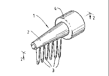
FIG. 1 shows the basic form of the dispensing nozzle in
perspective view;
FIG. 2 shows the dispensing nozzle of FIG. 1 in plan view
through points 2;

WO96/0668G 2 1 9 8 4 9 3 rcTl~u9sloo486
FIG. 3 shows a second example of the dispensing nozzle with a
central plunger for regulating the flow of liquid, in
perspective view;
~IG. 4 shows the dispensing nozzle of FIG. 3 in side plan
through ponts 2 and shows its connection to the container of
liquid;
~IG. 5 is the same as FIG. 4 but shows the view with the
plunger depressed so that liquid can flow from the container
into the dispensing head and nozzles;
FIG. 6 shows the dispensing nozzle of FIG. 3 in cross-
sectional view through points 4 in FIG. 5.
Referring to FIGS. 1 and 2, the preferred embodiment of the
dispensing nozzle 1 consists of a dispensing head 2 which is
hollow and from which a series of nozzles 3 extend more or
less at right angles and which are also hollow so that there
is ready access from the head. At one end of the head is a
means of attachment 4 to the container of liquid. In this
example the means of attachment is by an internally threaded
screw cap.
Referring to FIGS. 3 to 6, the second embodiment of the
dispensing nozzle 1 has, in addition to the features described
above, within the head, a plunger 5 which functions to seal
the head and prevent liquid flow. The end of the plunger 5 is
seen protruding from the end of the head opposite the
connection to the container of liquid.

' W096/06686 2 1 98493 PCT/~U95/00486
Referring now to FIGS. 2 and 3, the plunger 5 consists of a
sealing end 6 which is capable in the non-use position of
~eing seated securly in the neck 8 of the head. When in this
position no liquid can flow into the head. ~eading from the
sealing end 6 is an extension 7 which runs the length of the
head and passes through a hole in the end of the head to the
outside. The protruding portion of the extention is such that
when compressed the plunger is pushed laterally within the
head so that the sealing end is forced out of the neck of the
head a sufficient distance to allow a suitable flow of liquid
into the head and nozzles.

Representative Drawing
A single figure which represents the drawing illustrating the invention.
Administrative Status

2024-08-01:As part of the Next Generation Patents (NGP) transition, the Canadian Patents Database (CPD) now contains a more detailed Event History, which replicates the Event Log of our new back-office solution.

Please note that "Inactive:" events refers to events no longer in use in our new back-office solution.

For a clearer understanding of the status of the application/patent presented on this page, the site Disclaimer , as well as the definitions for Patent , Event History , Maintenance Fee  and Payment History  should be consulted.

Event History

Description Date
Inactive: IPC from MCD 2006-03-12
Inactive: Dead - No reply to s.30(2) Rules requisition 2004-02-16
Application Not Reinstated by Deadline 2004-02-16
Deemed Abandoned - Failure to Respond to Maintenance Fee Notice 2003-08-14
Inactive: Abandoned - No reply to s.30(2) Rules requisition 2003-02-14
Inactive: Entity size changed 2002-08-29
Inactive: S.30(2) Rules - Examiner requisition 2002-08-14
Inactive: Application prosecuted on TS as of Log entry date 2001-05-03
Inactive: Status info is complete as of Log entry date 2001-03-12
Amendment Received - Voluntary Amendment 2001-01-05
Inactive: Adhoc Request Documented 2000-06-22
Inactive: Delete abandonment 2000-06-22
Inactive: Abandoned - No reply to s.30(2) Rules requisition 2000-04-04
Inactive: S.30(2) Rules - Examiner requisition 1999-10-04
Inactive: Adhoc Request Documented 1999-06-21
Inactive: Delete abandonment 1999-06-21
Inactive: Abandoned - No reply to s.30(2) Rules requisition 1999-03-09
Inactive: S.30(2) Rules - Examiner requisition 1998-11-09
Inactive: Inventor deleted 1997-08-27
Inactive: Applicant deleted 1997-08-27
All Requirements for Examination Determined Compliant 1997-02-25
Request for Examination Requirements Determined Compliant 1997-02-25
Application Published (Open to Public Inspection) 1996-03-07

Abandonment History

Abandonment Date Reason Reinstatement Date
2003-08-14

Maintenance Fee

The last payment was received on 2002-08-14

Note : If the full payment has not been received on or before the date indicated, a further fee may be required which may be one of the following

  • the reinstatement fee;
  • the late payment fee; or
  • additional fee to reverse deemed expiry.

Please refer to the CIPO Patent Fees web page to see all current fee amounts.

Fee History

Fee Type Anniversary Year Due Date Paid Date
MF (application, 3rd anniv.) - small 03 1998-08-14 1998-05-06
MF (application, 4th anniv.) - small 04 1999-08-17 1999-08-13
MF (application, 5th anniv.) - small 05 2000-08-14 2000-07-07
MF (application, 6th anniv.) - small 06 2001-08-14 2001-08-07
MF (application, 7th anniv.) - standard 07 2002-08-14 2002-08-14
Owners on Record

Note: Records showing the ownership history in alphabetical order.

Current Owners on Record
PHILLIP GAZZO
Past Owners on Record
None
Past Owners that do not appear in the "Owners on Record" listing will appear in other documentation within the application.
Documents

To view selected files, please enter reCAPTCHA code :


To view images, click a link in the Document Description column. To download the documents, select one or more checkboxes in the first column and then click the "Download Selected in PDF format (Zip Archive)" or the "Download Selected as Single PDF" button.

List of published and non-published patent-specific documents on the CPD .

If you have any difficulty accessing content, you can call the Client Service Centre at 1-866-997-1936 or send them an e-mail at CIPO Client Service Centre.


Document
Description 
Date
(yyyy-mm-dd) 
Number of pages   Size of Image (KB) 
Representative drawing 1997-12-12 1 7
Description 2001-05-02 7 270
Claims 2001-05-02 2 61
Cover Page 1998-06-02 1 14
Cover Page 1997-05-26 1 14
Abstract 1996-03-04 1 9
Description 1996-03-04 6 176
Drawings 1996-03-04 2 46
Claims 1996-03-04 3 74
Courtesy - Abandonment Letter (R30(2)) 2003-04-28 1 167
Courtesy - Abandonment Letter (Maintenance Fee) 2003-09-11 1 176
Fees 1998-05-06 1 41
PCT 1997-02-25 22 1,012
Fees 2001-08-07 1 33
Fees 2002-08-14 1 37
Fees 1999-08-13 1 34
Fees 2000-07-07 1 34
Fees 1997-05-22 1 43
Fees 2000-07-07 1 37
Fees 2001-08-07 1 39