Note: Descriptions are shown in the official language in which they were submitted.
WO 9GJ065G9 ~ ~ ~ ~ ~' ~ ~ PCT/IB95J0092?
-1-
PHY&IOLOGIC TOURNIQUET
FIELD OF THE INVENTION
This invention pertains to physiologic
tourniquets for use in surgery. In particular, the
invention pertains to an electrically powered
tourniquet having a configuration register for
optimizing, customizing, simplifying, and reducing the
time required for configuring tourniquet pressure
settings, elapsed time limits and other parameters of
tourniquet operation. The invention also pertains to a
physiologic tourniquet having an event register for
registering predetermined events during surgery
concerning the application of pressure to a limb fox
occluding blood flow and for maintaining intravenous
regional anesthesia, in order to help improve patient
outcomes and reduce recurrences of tourniquet-related
events associated with injuries to patients.
BACKGROUNp OF THE INVENTION
This invention pertains to tourniquets for
facilitating surgical procedures performed on upper and
lower limbs. Surgical tourniquets are generally
employed to establish a bloodless operative field in a
limb distal to an encircling cuff by regulating a
pressure applied to the limb by the cuff near a pressure
sufficient to stop arterial blood flow past the cuff
during the surgical procedure. Surgical tourniquets of
the prior art typically include an inflatable cuff for
encircling a limb, an automatic pressure regulator for
inflating the cuff to maintain a pressure applied by the
cuff to the limb near a reference pressure selected by
an operator or determined automatically, an elapsed time
indicator to indicate the duration of application of
pressure to the limb and an operator interface to
facilitate operator control and interaction. A typical
pneumatic tourniquet of the prior art is disclosed by
McEwen in U.S. Patent Number 4,469,099.
A "physiologic tourniquet" is generally
considered to be a tourniquet which has the capability
CA 02198498 2005-05-24
77459-5
-2-
of maintaining the pressure applied by the cuff to the limb
near the minimum pressure required to stop the flow of
arterial blood past the cuff during the surgical procedure.
This minimum pressure is affected by variables related to the
physuology of the surgical patient, the type of surgical
procedure to be performed and its likely duration, the type of
cuff employed and its location and snugness on the limb, the
technique employed by the surgeon and the anesthetist, and
other factors. Tourniquet apparatus useful in automatically
estimating and employing such a minimum pressure is disclosed
by McEwen in U.S. Patent No. 4,479,494, in U.S. Patent
No. ~~,770,175 and in U.S. Patent No. 5,439,477.
Surgical tourniquets are typically employed as
follows. A suitable inflatable cuff is first selected by an
operator and applied snugly to the limb on which surgery is
to be' performed so that the cuff is located between the heart
and t=he operative site on the limb. Considerations involving
the design, selection and application of cuffs have been
described by McEwen, for example in U.S. Patent No. 4,605,010,
in U.S. Patent No. 5,181,522 and in U.S. Patent No. 5,312,431.
After application of a suitable cuff, the portion of the limb
distal to the cuff is then exsanguinated, often by wrapping
the .Limb with an elastic bandage, beginning at the end of the
limb and wrapping tightly towards the heart up to the cuff
locat=ion. While the limb is thus exsanguinated, the
tourniquet instrument is typically used to inflate the cuff
and maintain it at a predetermined cuff pressure sufficient
to st=op the inflow of arterial blood past the cuff. The
Blast=is bandage is then removed and surgery proceeds. The
pressure applied by the cuff may be changed periodically or
continuously during the surgical procedure in an effort to
maintain a bloodless surgical site while employing the
minimum cuff pressure required to do so,
WO 961Ob.569 1~ ~ ~ PCTlIB95100927
-3-
as explained more fully below. Upon completion of the
surgical procedure, the cuff is depressurized and
removed fram the patient, allowing arterial blood to
flow freely into the limb.
Buring certain surgical procedures performed
under intravenous regional anesthesia (IVRA), the
surgical tourniquet system serves an additional role of
preventing liquid anesthetic agent introduced into the
veins in the limb distal to the cuff from flowing
proximally past the cuff and out of the limb into the
circulatory system. For surgical procedures where IVRA
is to be employed, special cuffs having dual bladders of
narrower widths are often used for encircling the limb,
resulting in a first bladder encircling the limb above a
second bladder which also encircles the same limb distal
to the first bladder. Alternatively, two separate
single-bladder cuffs of greater widths can be applied to
the same limb. To maintain the pressures applied by one
dual-bladder cuff or two single-bladder cuffs near
selected reference pressures, one tourniquet instrument
having a dual-channel automatic pressure regulator may
be employed, or two separate tourniquet instruments,
each having one automatic pressure regulator, may be
employed. Prior art tourniquet apparatus for
intravenous regional anesthesia is described by McEwen
in U.S. Patent No. 5,254,087.
Before the commencement of a surgical
procedure, an operator typically configures a pneumatic
tourniquet of the prior art as follows. Upon the
initial supply of electrical power to a tourniquet of
the prior art having one or two pneumatic channels, the
levels of puff reference pressures and time limits for
elapsed time indicators and alarms are automatically set
to standard, arbitrary default levels sat by the
manufacturer. The operator may then employ controls and
displays forming part of the operator interface to
change the configuration of the cuff reference pressures
and the time limits to levels appropriate for the
WO 96!06569 ~ ~ ~ PCfliB95tf)0927
-4-
patient's physiology, the type of surgical procedure to
be performed and its probable duration, the type of cuff
employed and its snugness of application, and the
technique to be employed by the surgeon and anesthetist.
Often such changes to the configuration are not made,
because an operator does not have sufficient time
available to do so, or because an operator has not been
trained in how to make the changes, or because an
operator has not been trained concerning what levels to
set on the-basis of the variables listed above. If such
changes to the configuration are not made by an
operator, then the performance of the tourniquet will be
sub-optimal. Excessively high or low reference pressures
will result-in either a higher probability of nerve
injury in the limb encircled by the cuff or leakage of
blood and in some cases liquid anesthetic agent. Also,
a sub-optimal time limit either will result in a
significant reduction or elimination of the utility of
warning the surgeon of an excessive period of cuff
pressurization for a particular procedure surgical value
of elapsed time alarms in reducing tourniquet time if
the time limit setting is excessively high, or will
result in an annoyance and distraction to surgical and
anesthesia staff if the time limit setting is too low.
Even if an electrically powered. pneumatic
tourniquet of the prior art has been conFigured by an
operator to have levels of reference pressures and time
limits which are more appropriate than the arbitrary
default levels set when electrical power is first
supplied, such configured levels are not retained upon
the inadvertent or intentional interruption of
electrical-power to such prior art tourniquets. Upon
the resumption of electrical power to such prior art
tourniquets, the reference pressures and time limits are
again set to the same arbitrary and sub-optimal default
levels.
The applicant is unaware of any electrically
powered surgical tourniquet in the prior art having the
R'O 96106569 2 1 9 8 4 9 8 p~~9s~00927
-5-
capability of optimizing, customizing, simplifying, and
reducing the time required for, the configuration of the
tourniquet on the basis of patient physiology, type of
surgical procedure, type of cuff employed and operator
technique, so that parameters such as the reference
pressure levels and the levels of elapsed time limits
can be set to near-optimum levels either automatically
or by an operator, retained during an inadvertent or
intentional interruption of electrical power to the
tourniquet, and reproduced as the initial configuration
parameter levels upon a resumption of the supply of
electrical power to the tourniquet.
Regardless of how parameters such as the
reference pressures and time limits are initially
configured in a surgical tourniquet, a large number of
different events occurring during a surgical procedure
and associated with tourniquet usage affect patient
safety, the quality of the bloodless surgical field
distal to the tourniquet cuff, and longer-term patient
outcomes. For example, as mentioned above, it is
recognized that the level, distribution, and duration of
pressure applied by the cuff to the limb will affect the
nature and extent of injuries associated with tourniquet
usage. It is now generally known that every usage of a
surgical tourniquet results in some patient injury, and
it is thought that the nature and extent of such injury
can be minimized by improved setting, regulation and
monitoring of the level, distribution and duration of
the pressure applied by the tourniquet, by promptly
identifying and responding to potentially hazardous
events involving tourniquet usage, and by post-
operatively relating incidents, hazards and undesirable
outcomes such as nerve damage or paralysis, muscle
weakness and soft tissue damage to pertinent intra-
operative events associated with tourniquet usage.
These events associated with the use of a
tourniquet include: each change in the level of the
reference pressure employed by the pressure regulator of
W O 9b/065b9 219 ~ 4 9 8 PCTIIB95J04927
-6-
a tourniquet over the duration of tourniquet usage; any
significant differences between the pressure applied by
the cuff and the reference pressure; any applied
pressures which exceed, or which are less than,
predetermined upper or lower pressure limits
respectively; and the application of pressure for a time
period greater than a predetermined limit. Events may
be further c9efined to include the level of the reference
pressure or the level of the actual pressure applied by
the cuff at periodic intervals throughout tourniquet
usage, so that the quality of the bloodless surgical
field and any hazards, injuries and undesirable patient
outcomes cait be related to the complete pressure-time
set of events. Tn surgical procedures where TVStA is
employed, additional events occur which are associated
with tourniquet usage and which affect patient safety,
the quality of the intravenous regional anesthesia, and
patient outcomes. These IVRA-related events include the
sequence, timing and duration of pressurization and de-
pressurization of the bladders of a dual-bladder cuff or
dual cuffs at various times during the surgical
procedure, for reasons specifically related to the IVRA
technique
Typically in the prior art, some of such
predetermined events are noted by surgical or anesthesia
staff and are recorded manually in surgical or
anesthesia records. For example, many operators record
total tourniquet time and the initial reference pressure
level. However, such manual recording of events is
incomplete and inconsistent within institutions, among
institutions, and even among individuals in the same
operating room. Also, the recording of significant
events may'-.be delayed or not be done at all, as the
surgical staff may be attending to the patient as a
result of the occurrence of such significant events.
the applicant is not aware of any electrically
powered tourniquet having the capability of registering
the occurrence during limb surgery of any one of a
2198498
WO 9GIU65G9 PCT/iB95/UU927
number of such predetermined events concerning the
application of pressure to the limb for occluding blood
flow and maintaining IVRA, so that the registered events
are retained during an inadvertent or intentional
interruption of electrical power to the tourniquet, and
so that the registered events can be displayed for an
operator or reproduced on demand, after the restoration
of electrical power.
In the prior art, some electrically powered
tourniquets have employed pressure regulators which
incorporate electro-pneumatic valves. Some of these
prior-art tourniquets, such as the ATS 1500 Automatic
Tourniquet System manufactured by Zimmer Inc.' of Dover
OH, use one valve for inflation and one valve for
deflation of each cuff and incorporate a safety circuit
for detecting and responding safely to a limited range
of abnormal and hazardous actuations of the valves.
However, the applicant is not aware of any tourniquet in
the prior art which has multiple inflation valves and
multiple deflation valves and which also has a safety
circuit for detecting and responding safely to a wide
range or valve related hazards including certain non-
actuations of the valves, failure of one of the multiple
inflation or deflation valves, or abnormal or undesired
actuations of combinations of valves.
SU29~SARY OF THE INVENTION
The present invention is to provide
electrically powered tourniquet apparatus having
improved speed and simplicity of configuration prior to
initial use, or following an inadvertent or intentional
interruption of electrical power, by incorporating a
configuration register which configures the initial
pressure setting of the pressure regulator to be a
pressure previously selected by an operator or
previously determined automatically. Also provided is
an electrically powered tourniquet apparatus
incorporating a configuration register which configures
the initial setting of an elapsed time limit to be a
CA 02198498 2005-05-24
7745~a-5
_g_
time limit previously selected by an operator or previously
determined automatically.
Also provided is a physiologic tourniquet
apparatus having an event register which provides capability
for relating, either intra-operatively or post-operatively,
the occurrence of incidents, hazards and undesirable
outcomes such as nerve damage or paralysis, muscle weakness,
soft tissue damage, and IVRA-related problems, to pertinent
intra-operative events associated with tourniquet usage.
The Event register records the occurrence during limb
surgery of any one of a number of events concerning the
application of pressure to the limb for occluding blood
flow, and in some instances for maintaining intravenous
regional anesthesia, so that the recorded events are
reta~_ned during any inadvertent or intentional interruption
of e7_ectrical power to the tourniquet, and so that the
recorded events can be displayed for an operator or
reproduced on demand, including at any time after the
restoration of electrical power if it has been interrupted.
Also provided is an electrically powered
tourniquet apparatus incorporating a safety circuit which
will detect and respond safely to undesired valve actuations
during different modes of operation of the pressure
regulator.
In accordance with a first broad aspect, the
invention provides an electrically operated physiologic
tourniquet system, comprising: a pressurizing cuff for
encircling and applying pressure to a limb; selector means
for permitting an operator to select an initial reference
pres:~ure level; configuration register means for enabling
the operator to record in a memory the selected initial
reference pressure level, wherein the memory retains the
CA 02198498 2005-05-24
77459-5
-8a-
recorded initial reference pressure level irrespective of
whether power to the system is interrupted; the
conf_Lguration register means including selector read means
for periodically determining whether the operator has
changed the initial reference pressure level, and regulator
mean; for retrieving from the memory at the beginning of
each use of the system the last recorded initial reference
pressure level, and for regulating the pressure in the cuff
to be' near the retrieved initial reference pressure level;
the regulator means including recommended cuff pressure
mean; for determining the minimum pressure applied by the
cuff to the limb that prevents blood flow past the cuff, and
for determining as a function of the minimum pressure a
recommended cuff pressure to be applied to the cuff, and for
enabling the operator to record the recommended cuff
pres:~ure in memory as the initial reference pressure level.
In accordance with a second broad aspect, the
invention provides an electrically operated physiologic
tourniquet system, comprising: an inflatable and deflatable
cuff,; selector means for displaying to an operator
selections of initial time limits and for permitting the
operator to select one of the displayed initial time limits
and too change the selected one of the initial time limits;
conf=Lguration register means for enabling an operator to
record in a memory the selected initial time limit and for
periodically determining whether the operator has changed
the initial time limit, wherein the memory retains the last
recorded initial time limit irrespective of whether power to
the :system is interrupted; and timing means for retrieving
from the memory at the beginning of each use of the system
the .Last recorded initial time limit, for monitoring a time
period, and for alerting the operator when the time period
equals the time limit.
CA 02198498 2005-05-24
77459-5
-8b-
In accordance with a third broad aspect, the
invention provides an electrically operated physiologic
tourniquet system, comprising: an inflatable and deflatable
cuff,; regulator means for regulating the pressure in the
cuff to be near a reference pressure level; selector means
for permitting an operator to change the reference pressure
leverL; and event register means for automatically recording
the changed reference pressure level and the time that the
change occurred.
In accordance with a fourth broad aspect, the
invention provides a method of operating an electrically
operated physiologic tourniquet system, that has an
inflatable and deflatable cuff, the method comprising the
steps of: beginning each new use of the system by
retrieving from a memory an initial reference pressure
level; regulating the pressure in the cuff to be near the
initial reference pressure level; and permitting an operator
to sE:lect the initial reference pressure level and to store
in the memory the selected initial reference pressure
irre:apective of whether power to the system is interrupted.
In accordance with a fifth broad aspect, the
invention provides a physiologic tourniquet system
comprising: an inflatable and deflatable cuff for
encircling and applying pressure to a limb; at least one
pressure source selectably pneumatically connected to the
cuff,; at least one exhaust line selectably connected to the
cuff,; a microprocessor that determines when to inflate the
cuff,, deflate the cuff, or regulate the pressure in the
cuff, and that produces a cuff mode signal having one of a
plurality of predefined signals indicative of whether to
inflate, deflate or regulate the pressure in the cuff; a
first inlet valve responsive to a first inlet valve
actuation signal and a first inlet valve deactuation signal
CA 02198498 2005-05-24
77459-5
-8c-
from the microprocessor, wherein the first inlet valve is
opened by the first inlet valve actuation signal to
pneumatically connect the pressure source to the cuff, or
deact=uated by the first inlet valve deactuation signal to
closes the pneumatic connection between the cuff and pressure
source; a first inlet valve status output signal from the
first. inlet valve to indicate whether the first inlet valve
is actuated or deactuated; and a safety circuit that
monitors the cuff mode signal and the first inlet valve
status output signal for undesired combinations of cuff mode
signal and first inlet valve status output signal and
produces a fault signal if an undesired combination is
detected.
In accordance with a sixth broad aspect, the
invention provides a physiologic tourniquet system
compi:ising: an inflatable and deflatable cuff for
encircling and applying pressure to a limb; at least one
pres~~ure source selectably pneumatically connected to the
cuff; at least one exhaust line selectably connected to the
cuff; a microprocessor that determines when to inflate the
cuff, deflate the cuff, or regulate the pressure in the
cuff, and that produces a cuff mode signal having one of a
plur~rlity of predefined signals indicative of whether to
infl~rte, deflate or regulate the pressure in the cuff; a
first: exhaust valve responsive to a first exhaust valve
actuation signal and a first exhaust valve deactuation
signal from the microprocessor, wherein the first exhaust
valve is opened by the first exhaust valve actuation signal
to pneumatically connect the cuff to the exhaust line, or
deact:uated by the first exhaust valve deactuation signal to
close: the pneumatic connection between the cuff and the
exhaust line; a first exhaust valve status output signal
from the first exhaust valve to indicate whether the first
CA 02198498 2005-05-24
~~45~a-s
-8d-
exhaust valve is actuated or deactuated; and a safety
circuit that monitors the cuff mode signal and the first
exhaust valve status output signal for undesired
comb_Lnations of cuff mode signal and first exhaust valve
status output signal and produces a fault signal if an
unde;~ired combination is detected.
In accordance with a seventh broad aspect, the
invention provides a physiologic tourniquet system,
comprising: an inflatable and deflatable cuff; a
microprocessor that determines when to inflate the cuff,
deflate the cuff, and regulate the pressure in the cuff, and
that produces respective cuff mode signals from a plurality
of predefined levels to inflate, deflate and regulate the
pres:~ure in the cuff; a regulator responsive to the cuff
mode signal for inflating the cuff, deflating the cuff and
regu~~_ating the pressure in the cuff; and a safety circuit
operable independently of the microprocessor and responsive
to the cuff mode signal and having a plurality of stored
leve7_s for the cuff mode signal, wherein the safety circuit
operates by comparing the level of the cuff mode signal to
the plurality of levels for the cuff mode signal and
produces a microprocessor fault signal when the cuff mode
signal level does not correspond to one of the sets of
stored levels .
In accordance with an eighth broad aspect, the
invention provides an electrically operated physiologic
tourniquet system, comprising: an inflatable and deflatable
cuff for encircling and applying pressure to a limb; a
pres~~ure source for supplying pressurized gas to the cuff;
first: and second valves through which the pressure source is
independently connected to the cuff; regulator means for
producing a cuff mode signal and first and second inlet
valvE: actuation signals; and wherein the pressure source is
CA 02198498 2005-05-24
7745~a-5
-8e-
selectively pneumatically connected to the cuff through
actuation of the first or second valves by the regulator
mean:, and a safety circuit senses preset undesired
comb_Lnations of the cuff mode signal and actuation of the
first. and second valves, and produces a fault signal in
response to detection of any of the undesired combinations;
and wherein the cuff is connected to an exhaust line through
actuation of separate third or fourth valves by the
regu_Lator means, and the safety circuit senses preset
unde;~ired combinations of the cuff mode signal and actuation
of the third and fourth valves, and produces the fault
signal in response to detection of~any of the undesired
comb_Lnations of the cuff mode signal and actuation of the
third and fourth valves.
BRIEF DESCRIPTION OF THE DRAWINGS
FIG. 1 is a pictorial representation of the
preferred embodiment in a surgical application.
FIG. 2 is a block diagram of the preferred
embodiment.
FIGS. 3a, 3b, 3c and 3d are pictorial
representations of the layout of the display panel of the
preferred embodiment in different clinical applications.
FIGS. 4, 5, 6, 7, 8 and 9 are software flow charts
depicting the control software of the preferred embodiment.
W096106i69 ~~ PCT/IB9i100927
_g_
FIG. 10 is a block diagram of a valve assembly
of the preferred embodiment.
nFSC~RIPTION OF THE PREFERRED EMBODIMENT
The embodiment illustrated is not intended to
be exhaustive or limit the invention to the precise form
disclosed. It is chosen and described in order to
explain the principles of the invention and its
application and practical use, and thereby enable others
skilled in the art to utilize the invention. The
preferred embodiment of the invention is described in
three sections below: hardware; operation and software.
I. Hardware
FIG. 1 depicts instrument 2 connected to
pressurizing cuff 4 and pressurizing cuff 6, which cuffs
can be inflated to apply pressures to patient limb 8.
In FIG. 1, photoplethysmographic blood flow sensor 10 is
shown applied to a digit of limb 8 distal to cuff 4 and
cuff 6, and connected to instrument 2. For clarity,
cuff 4 and cuff 6 have been shown as separate cuffs
applied to the same limb 8, but in practice the separate
cuffs may be applied to different limbs of a patient, or
they may be combined as separate bladders of one dual-
bladder inflatable cuff applied to a single limb of a
patient, depending upon the surgical procedure being
performed and the type of anesthesia employed. In many
types of surgical procedures, only cuff 4 is employed
and cuff 6 is not used.
As can be seen in FIG. 1, cuff 4 is connected
pneumatically by tubing 12 and tubing 14 to instrument
2. Cuff 6 is connected pneumatically by tubing 16 and
tubing 18 to instrument 2.
Electroluminescent graphic display panel 20
(EL4737LP, Planar Systems, Beaverton, OR) shown in FIGS.
1 and 2 forms part of instrument 2 and is used to
display information to the user of instrument 2.
Display panel 20 is employed for the selective
presentation of any of the following information as
described below: (a) menus of commands for controlling
WO 9&f06569 PCTlIB95100927
-10-
instrument 2, from which a user may make selections; (b)
parameters having values which characterize the actual
cuff pressures, cuff inflation times, cuff pressure
reference levels and inflation time alarm limit values;
(c) text messages describing current alarm conditions,
when alarm conditions are determined by instrument 2;
(d) graphical representations of blood flow signals
produced. by sensor 10; and (e) messages which provide
operating information to the user.
Switch 22 (61-01032-10 Grayhill Inc., La
Grange, IL) shown in FIGS. 1 and 2, provides a versatile
means for the user to control instrument 2. Switch 22
is a rotary selector and push-button combination switch.
In combination with the electronic circuitry and
software described below, switch 22 operates by
producing signals in response to rotaticn of the
selector and activation of the push-button by the user.
In the preferred embodiment, rotating switch 22 allows
the user to select a specific menu command or parameter
for adjustment from those shown on display panel 20.
The currently selected menu command or parameter is
"highlighted" by being displayed in reverse vfdea. If a
menu command is "highlighted", pushing then releasing
switch 22 causes the action indicated by the menu
command to he performed. If a parameter is
"highlighted"; the value of the parameter can then be
adjusted by pushing and releasing switch 22, and then
rotating switch 22: clockwise rotation will cause the
value of the parameter to be increased; eounter-
clockwise rotation will cause the value of the parameter
to be decreased; pushing and releasing the switch 22
again comple es the adjustment of the parameter, and
allows other menu commands or parameters to be selected
in response to subseguent rotation of switch 22.
Zss can he seen in FIG. 2, Buff 4 is connected
pneumatically by tubing 12 to pressure transducer 24,
and is connected pneumatically by tubing 14 to valve
assembly 26. Valve assembly 26 is shown in detail in
219 8 4 9 g PCTIIB95/UU927
W 0 96106569
-11-
FIG. 10 and further described below. Valve assembly 26
responds to certain signals generated by microprocessor
28 (80C196RB, INTEL Corp., Santa Clara, CA) to
pneumatically connect tubing 14 through tubing 32 to gas
pressure reservoir 34, a sealed pneumatic chamber having
a fixed volume of 500m1. Valve assembly 26 also
responds to other signals generated by microprocessor 28
to pneumatically connect tubing 14 to atmosphere,
allowing the release of pressure in cuff 4. Valve
sensing circuit 1020 (FIG. 10) included in valve
assembly 26 responds to a cuff 4 mode signal generated
by microprocessor 28 which is indicative of a predefined
cuff mode; in the preferred embodiment three cuff modes
for cuff 4 are defined: "cuff inflating" mode, "cuff
regulating" mode and "cuff deflating" mode. The level
to which the cuff 4 mode signal is set by microprocessor
28 is determined by user input and microprocessor 28.
Pressure transducer 24 generates a cuff 4 pressure
signal which indicates the pressure of gas in cuff 4,
and the cuff 4 pressure signal is then communicated to
an analog to digital converter (ADC) input of
microprocessor 28 which digitizes the cuff 4 pressure
signal. When the cuff 4 mode signal is at a level
indicative of "cuff inflating" mode, microprocessor 28
acts to increase the level of pressure within cuff 4
from a level near atmospheric pressure to a level near
the reference pressure represented by the cuff 4
reference pressure signal, by generating signals for the
actuation of valves 1002 and 1004 (FIG. 10) within valve
assembly 26, thereby pneumatically connecting cuff 4 to
a gas pressure reservoir 34. When the cuff 4 mode
signal is at a level indicative of "cuff regulating"
mode microprocessor 28 acts to regulate the pressure
within cuff 4 near the reference pressure represented by
the cuff 4 reference pressure signal by generating
signals for the selective actuation of either valves
1002 or 1006 within valve assembly 26, thereby
pneumatically connecting cuff 4 to gas pressure
W O 96706565 ~ 19 g 4 9 g PCT1IB95100927
-1.2-
reservoir 34 or pneumatically correcting cuff 4 to
atmosphere. When the cuff 4 mode signal is at a level
indicative of "cuff deflating" mode, microprocessor 28
acts to reduce the level of pressure within cuff 4 to a
Level near atmospheric pressure by generating signals
for the actuation of valves 1006 and 1010 within valve
assembly 26, thereby pneumatically connecting cuff 4 to
atmosphere. To alert the user if the pressure in cuff 4
can not be regulated within a pre-assigned limit of ~15
mmHg, microprocessor 28 compares the cuff pressure
signal from cuff pressure transducer 24 to the reference
pressure signal for cuff 4: if the cuff pressure signal
exceeds the reference signal by 15 mmHg or more,
microprocessor 28 generates an alarm signal indicating
over-pressurization of cuff 4. If the cuff pressure
signal is less than the reference pressure signal by a
difference of 15 mmHg or more, microprocessor 28
generates an alarm signal indicating under-
pressurizat3.on of cuff 4. Microprocessor 28 also tracks
the inflation time for cuff 4, by maintaining a counter
indicating the length of time that cuff 4 has been
pressurized. Microprocessor 28 compares this actual
cuff inflation time to an inflation time limit for cuff
4, and if the actual cuff inflation time exceeds the
inflation time limit, microprocessor 28 generates an
alarm signal indicating that the inflation time limit
for cuff 4 has been exceeded.
Ids depicted in FIG. 2, if cuff 6 is required
for the surgical application, cuff 6 is connected
pneumatically by tubing 16 to pressure transducer 36,
and is connected pneumatically by tubing 18 to valve
assembly 38. Valve assembly 38 has the same structure
as valve assembly 26 which is described in detail below
and which ~s shown in FIG 10. Valve assembly 38
responds to signals described below which are generated
by microprocessor 28, to pneumatically connect tubing 18
through tubing 32 to gas pressure reservoir 34. Valve
assembly 38 also responds to other signals described
WO 9bPO65b9 219 8 4 9 B PC1'lIB95/OU927
-13-
below which are generated by microprocessor 28 to
pneumatically connect tubing 18 to atmosphere, allowing
the release of pressure in cuff 6. Valve assembly 38
responds to a cuff 6 mode signal generated by
microprocessor 28 which is indicative of a predefined
cuff mode; in the preferred embodiment three modes for
cuff 6 are predefined: "cuff inflating" mode, "cuff
regulating" mode, and "cuff deflating" mode. The level
to which the cuff 6 mode signal is set by microprocessor
28 is determined by user input and microprocessor 28.
Pressure transducer 36 generates a cuff 6 pressure
signal which indicates the pressure of gas in cuff 6,
and the cuff 6 pressure signal is then communicated to
an analog to digital converter (ADC) input of
microprocessor 28 which digitizes the cuff 6 pressure
signal. When the cuff 6 mode signal is at a level
indicative of "cuff inflating" mode, microprocessor 28
acts to increase the level of pressure within cuff 6
from a level near atmospheric pressure to a level near
the reference pressure represented by the cuff 6
reference pressure signal, by generating signals for the
actuation of selected valves within valve assembly 38.
When the cuff 6 mode signal is at a level indicative of
"cuff regulating" mode microprocessor 28 acts to
regulate the gressure within cuff 6 near the reference
pressure represented by the cuff 6 reference pressure
signal by generating signals for the actuation of
selected valves within valve assembly 38. When the cuff
6 mode signal is at a level indicative of "cuff
deflating" mode, microprocessor 28 acts to reduce the
level of pressure within cuff 6 to a level near
atmospheric pressure by generating signals for the
actuation of selected valves within valve assembly 38.
To alert the user if the pressure in cuff 6 can not be
regulated within a pre-assigned limit of ~15 mmHg,
microprocessor 28 compares the cuff pressure signal from
cuff pressure transducer 36 to the reference pressure
signal for cuff 6: if the cuff pressure signal exceeds
W096106569 ~ 9~ pCTlIB95/00927
-14-
the reference signal by 15 mmHg or more, microprocessor
28 generates an alarm signal indicating over-
pressurization of cuff 6. If the cuff pressure signal
is less than the reference pressure signal by a
difference of 7.5 mmHg or more, microprocessor 28
generates an alarm signal indicating under-
pressurization of cuff 6. Microprocessor 28 also tracks
the inflation time for cuff 6, by maintaining a counter
indicating the length of time that cuff 6 has been
pressurized. Microprocessor 28 compares this actual
cuff inflation time to an inflaticn time limit for cuff
6, and if the actual cuff inflation time exceeds the
inflation time limit, microprocessor 28 generates an
alarm signal indicating that the inflation time limit
for cuff 6 has been exceeded.
As shown in FIG. 2, pneumatic pump 40 (E
series 801105, Gilian Instrument Corp. Caldwell, NJj is
pneumatically connected to reservoir 34 by tubing 42.
Pump 40 acts to pressurize reservoir 34 in response to
control signals from microprocessor 28 communicated
through pump driver 44. Reservoir pressure transducer
46 is pneumatically connected through tubing 48 to
reservoir 34 and generates a reservoir pressure signal
indicative of the pressure in reservoir 34. The
reservoir pressure signal is communicated to an ADC
input of microprocessor 28. In response to this
reservoir pressure signal and a reservoir pressure
reference signal provided as described below,
microprocessor 28 generates control signals for pump
driver 44 and regulates the pressure in reservoir 34 to
a pressure near the reference pressure represented by
the reservoir reference pressure signal as described
below.
photoplethysmographic blood flow sensor 10 is
placed on ~ portion of a limb distal to cuff 4, and
distal to cuff 6 if cuff 6 is also employed, to sense
blood flow beneath the flow sensor 10. FIG. 1
illustrates a typical location of sensor 10 far the
W O 4bIUti569 ~ ~ PCTIIB95100927
-15-
lower limb. Sensor 10 generates a blood flow signal
indicative of blood flow beneath the sensor, which is
processed by amplifier 50 and communicated to an ADC
input of microprocessor 28, as depicted in FIG. 2.
Real time clock 52 shown in FIG. 2 maintains
the current time and date, and includes a battery as an
alternate power source such that clock operation
continues during any interruption in the supply of
electrical power from power supply 54 required for the
normal operation of instrument 2. Microprocessor 28
communicates with real time clock 52 for both reading
and setting the current time and date.
Configuration register 56 shown in FIG. 2 is
comprised of non-volatile memory (24LC02, Microchip
Technology, Chandler AZ) operating in conjunction with
microprocessor 28 as described below to contain
previously recorded cuff reference pressure levels and
inflation time alarm limits for use by microprocessor 28
as described below, and retains these recorded levels
of these parameters indefinitely in the absence or
interruption of electrical power from power supply 54
required for the normal operation of instrument 2. The
levels of the cuff reference pressures and inflation
time limits initially recorded in configuration register
56 are given in the table below:
Operating Mode Cuff 4 referenceCuff 4 inflationCuff 6 referenceCuff 5
inflation
pressure time limit pressure time limit
Single Cuff Mode200 mmHg 60 Min. - -
200 nunH 60 Min.
Dual Cuff Mode 200 mmHg 60 Min. g
IVRA Dual Bladder
3 Cuff Mode 250 nunHg 45 Min 250 mmHg 45 Min.
0
Microprocessor 28 communicates with
configuration register 56 to record and retrieve levels
of the configuration parameters recorded in
configuration register 56 as described below.
Event register 58 shown in FIG. 2, records
"events" which are defined in the software of the
WO 961116569 pCT;lg9il00927
-16-
preferred embodiment to be: (a) actions by the user to
inflate a cuff, deflate a cuff, adjust the level of a
cuff reference pressure signal, adjust the level of cuff
inflation time limit signal, adjust the level of the
operating mode signal or silence an audio alarm; (b)
alarm events, resulting from microprocessor 28
generating an alarm signal as described above; and (c)
events associated with determining a cuff pressure
automatically as described below. Event register 58
comprises event register memory 60 (28C64A Microchip
Technology, Chandler, RZ), and event register printer
62. Microprocessor 28 communicates with event register
58 to record events as they occur. Microprocessor 28
records an event by communicating to event register 58:
the time of the event as read from real time clock 52; a
value identifying which one of a specified set of events
occurred as determined by microprocessor 28; and the
values at the time of the event of the following
parameters: operating mode signal, cuff 4 pressure
signal; cuff 4 pressure reference signal; cuff 4
inflation time, cuff 4 inflation time limit; cuff 6
pressure signal; cuff 6 pressure reference signal; cuff
6 inflation time, cuff 6 inflation time limit; and
recommended cuff pressure, when the event occurred.
Entries are recorded in event register 58 by storing
values in event register memory 60 and by printing these
values for the user by means of event register printer
62. Event-register memory 60 retains information
indefinitely in the absence or interruption of
electrical power from power supply 54 required for the
normal operation of instrument 2.
Iiicroprocessor 28 communicates with
electroluminescent display panel 20 through display
controller ~4 to display information as described above.
User input is by means of switch 22. Signals
from switch 22 arising from rotation and push-button
contact closure in switch 22 are communicated to
microprocessor 28.
R'O 9GJ065G9 ~ ~ PCT/IB95100927
-17-
Microprocessor 28 will, in response to
generated alarm signals alert the user by text and
graphic messages shown on display panel 20 and by audio
tones. Electrical signals having different frequencies
to specify different alarm signals and conditions are
produced by microprocessor 28, amplified by audio
amplifier 66 and converted to audible sound by loud
speaker 68 shown in FIG. 2.
Pawer supply 54 provides regulated DC power
for the normal operation of all electronic and
electrical components.
Shown in FIG. 10 and described below is a
detailed block diagram of valve assembly 26 shown in
FIG. 2. When actuated, valve 1002 (EVO-3-60V Clippard
i5 Instrument Laboratory, Cincinnati, OH) pneumatically
connects tubing 32 to tubing 14, permitting the flow of
gas from reservoir 34 shown in FIG. 2 to cuff 4. Valve
1004 (201A3/30F Burkert Contromatic Corp., Orange, CA)
when actuated also pneumatically connects tubing 32 to
14. The valve orifice of valve 1004 is substantially
larger than the valve orifice of valve 1002 and
therefore permits gas to flow into cuff 4 at a greater
rate than valve 1002. Valve 1006 (EVO-3-60V Clippard
Instrument Laboratory, Cincinnati, OH) when actuated
pneumatically connects tubing 14 to tubing 1008. Tubing
1008 is open to atmosphere and permits gas to be
released from cuff 4. Valve 1010 (201A3/30F Burkert
Contromatic Corp., Orange, CA) when actuated also
pneumatically connects tubing 14 to tubing 1008. The
valve orifice of valve 1010 is substantially larger than
the valve orifice of valve 1006 and therefore permits
gas to be released from cuff 4 at a greater rate than
valve 1006. This combination of valves permits cuff 4
to be inflated and deflated rapidly through valves 1004,
1010, and also permits the pressure in cuff 4 to be
regulated accurately when inflated through valves 1002,
1006. Valve drivers 1012, 1014, 1016 and 1018, under
the control of signals from microprocessor 28, complete
WO 96106569 ~ ~ ~ PCTlIB95I00927
-18-
an electrical circuit allowing electrical power to be
applied for the actuation of valves 1002, 1004, 1006 and
1010 respectively.
Valve sensing circui 1020 in valve assembly
26 monitors the actuation of valves 1002, 1004, 1006 and
1010 by monitoring the voltage levels between the valve
drivers and the valves. If any one of the predetermined
set of undesired valve actuations described below is
detected, valve sensing circuit 1020 responds by
generating a "fault" signal that is sent to
microprocessor 28. valve circuit 1020 also responds by
discannecting the supply of electrical power to all
valves 1002, 1004, 1006, and 1010, thus de-actuating
valves 1002, 1004, 1006 and 1010. De-actuating valves
1002, 1004, 1006 and 1010, ensures. that the pressure
within cuff 4 will remain stable and will not increase
or decrease to unsafe levels as the result of an
undesired valve actuation. Microprocessor 28 responds
to the "fault" signal by generating an alarm signal
indicating that a valve related fault has occurred.
Undesired valve actuations may result from the failure
of any one of valve drivers 1012, 1014, 1016 or 1018, or
failure of. any one of valves 1002, 1004, 1006 and 1010,
or a failure in microprocessor 28, or a software error.
The table below summarizes the undesired combinations of
valve actuations which are detected by valve sensing
WO 9fi1~6569 ~ PCT/IB95100927
-19-
circuit 1020 for the three valid levels of the cuff mode
signal.
CUFF MODE Valve 1002Valve 1004Valve 1006 Valve 1010
SIGNAL
Cl~ff Deflating actuated x x x
Mode
l0 Ghff Deflating x actuated x x
Mode
Cuff Deflating x x de-actuatedde-actuated
Mode
Cuff Inflating x x actuated x
Mode
Cuff Inflating x x x actuated
Mode
Cuff Inflating de-actuatedde-actuatedx x
Mode
Cuff Regulating actuated x actuated x
2 MOde
5
Cuff Regulating x actuated x x
Mode
Cuff Regulating x x x actuated
Mode
x = either actuated or de-actuated
In the preferred embodiment, valve sensing
circuit 1020 depicted in FIG. l0 also responds to a cuff
mode signal generated by microprocessor 28. In the
preferred embodiment, the level of the cuff mode signal
for cuff 4 corresponds to one of three predefined
levels, each of which is indicative of one of three
modes: "cuff inflating" mode, "cuff regulating" mode and
"cuff deflating mode". The cuff regulating mode refers
to a mode of operation in which the cuff is maintained
at a preselected pressure by the system. The level of
the cuff mode signal determines which combinations of
R'O 96/06569 ~ ~ ~ PCTIIB9R/00927
-20-
valve actuations will be cia,ssified as undesired by the
valve sensing circuit 1020. Upon detecting an undesired
valve combination, or upon detecting a cuff mode signal
hawing a level other than one of three predefined levels
indicative of the three valid cuff modes, valve sensing
circuit 1020 generates a "fault" signal and disconnects
the electrical power supplied to valves 1002, 1004, 1006
and IOIO, thereby de-actuating valves 1002, 1004, 1006
and 1010. Deactuation of these valves maintains the
prior status of the system, and reduces the likelihood
of occurences of such undesired events as simultaneous
inflation and deflation of a cuff. An invalid cuff mode
signal may result from the failure of microprocessor 28
or a software error.
II. ousration
At start-up of instrument 2, when instrument 2
is activated by supply of electrical power through power
supply 54 microprocessor 28 configures instrument 2 by
setting predetermined parameters to the levels recorded
in configuration register 56. Configuration register 56
contains a~previously recorded lever for the operating
mode signal and, for each of the three possible levels
of the operating mode signal, previously recorded level
for the cuff reference pressure and cuff inflation time
alarm limit for each cuff, as described elsewhere. The
user of instrument 2 can alter a level of a parameter
recorded in configuration register 56, by selecting the
parameter and changing its level as described below.
In operation, a user of the preferred embodiment
communicates with instrument 2 by using switch 22 to
choose commands for controlling instrument 2 from menus
of commands, and by using switch 22 to set the level of
parameters displayed on display panel 20, as described
above and in the software description below.
Three distinct modes of operation of the
preferred .embodiment are provided in the preferred
embodiment: "Single Cuff Mode", "Dual Cuff Mode" and
"IVRA Dual-Bladder Cuff Mode". Microprocessor 28
~
2'9~~~8
WO 96Jfl6569 PCTlIB95100927
-21-
controls the operation of instrument 2 in response to
the level of the operating mode signal as described
below. The level of the operating mode signal is set by
microprocessor 28 retrieving a previously recorded level
from configuration register 56 and can be altered by the
user by means of switch 22 as described below.
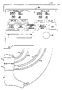
FIG. 3a shows the layout of display panel 20 for
"Single Cuff Mode", wherein only cuff 4 is actuated and
used in a surgical procedure. As depicted in FIG. 3a, a
single display region 70 labeled MAIN CUFF is shown on
display panel 20 and predetermined menu 72 is also
displayed for the user. Menu 72 enables choices to be
made by the user for: temporarily silencing audio
alarms; printing on event register printer 62 the events
recorded in event register memory 60; initiating the
determination of recommended cuff pressure; selecting an
operating mode, or obtaining operating instructions.
Menu 72 is depicted in FIG. 3a with the menu command
"SELECT OPERATING MODE" shown in reverse video,
indicating that it has been selected by the user of
instrument 2. As shown in FIG. 3a, within display
region 70 labeled MAIN CUFF parameters and menu commands
for controlling cuff 4 are displayed, and all displayed
parameters are continually updated by microprocessor 28.
The displayed parameters are: the current level of cuff
pressure, cuff pressure reference level, cuff inflation
time and inflation time alarm limit level. The menu
commands for control of cuff 4 are: "inflate" and
"deflate". If the user selects the command "inflate",
instrument 2 will regulate the pressure in cuff 4 near
the level of the cuff 4 reference pressure signal as
described above. If the user selects the command
"deflate" instrument 2 will release the pressure in cuff
4 causing cuff 4 to deflate to atmospheric pressure. In
"Single Cuff Mode" all alarm and event messages refer
only to cuff 4.
FIG. 3b depicts the layout of display panel 20
for "Dual Cuff Mode", corresponding to the second of
WO 96/06569 ~ ~ PCT1IB95f00927
_22_
three predetermined levels of the operating mode signal.
In "Dual Cuff Mode" both cuff 4 and cuff 6 are actuated.
As illustrated in FIG. 3b two independent display
regions are shown on display panel 20, as well as the
predetermined user menu 72 described above. One region
70 is labeled MAIN CUFF, within which region are
displayed the parameters and menu commands for control
of cuff 4. The second region 74 is labeled SECOND CUFF,
within which region are displayed the parameters and
controls for cuff 6. The parameters and controls
displayed i.n region 74 are identical to those described
above for cuff 4, except the parameters and controls
displayed in region 74 refer to cuff 6. In "Dual Cuff
Mode", the inflation and deflation of cuff' 4 is
independent of the inflation and deflation of cuff' 6.
All alarm and event messages refer either to cuff 4, the
MAIN CUFF or to cuff 6, th,e SECOND CUFF. When cuff 6 is
inflated in the "Dual Cuff Mode", the operating mode
signal cannot be changed by the user until such time as
cuff 6 has been deflated.
FIG. 3c depicts the layout of display panel 20
for the "TVRA Dual-Bladder Cuff Mode", corresponding to
the third level of the operating mode signal. This mode
can only be selected by the user when both cuff 4 and
cuff 6 are deflated. The "IVRA Dual-Bladder Cuff Mode"
is the preferred mode for selection by the user when
Intravenous Regional Anesthesia (IVR~) also known as
Bier block anesthesia, is employed. In "IVRA Dual-
Biadder Cuff Mode" both cuff 4 and cuff 6 are actuated.
As shown in FIG. 3c two independent display regions 76
and 78 are' hown on display panel 20, also shown is
predetermined user menu 72 having the structure and
function as described above. Region 76, labeled
PROXIMAL CUFF contains displays of parameters and
controls for cuff 4. Region 78,' labeled DISTAL CUFF
contains displays of the parameters and controls for
cuff 6. Alarm and event messages are generated to refer
separately either to cuff 4, the PROXIMAL CUFF, or to
219849
W O 96106569 PCTIIB95100927
-23-
cuff 6 the DISTAL CUFF. When the preferred embodiment
is operating in "IVRA Dual-Bladder Mode", the operating
mode signal cannot he changed by the user while either
cuff 4 or cuff 6 is inflated.
In "IVRA Dual-Bladder Cuff Mode" a safety
interlock is activated to reduce the probability of
unintended and inadvertent deflation of both cuffs
during a surgical procedure involving IVRA. The safety
interlock operates as follows: if the user initiates
deflation of cuff 4 while cuff 6 is deflated, or if the
user initiates deflation of the cuff 6 while cuff 4 is
deflated, a safety interlock signal is produced to
prevent the initiated deflation and a visual and audible
warning is given via display panel 20 and speaker 68 to
indicate to the user that the action the user has
initiated may be unsafe, i.e. that the action would
result in cuff 4 and cuff 6 being deflated at a time in
a surgical procedure involving IVRA when liquid
anesthetic agent contained in blood vessels distal to
cuff 4 and cuff 6 may be released into systemic
circulation. A menu command is displayed on display
panel 20 far enabling the user to confirm that deflation
of the cuff is intended. To continue with the initiated
deflation, the user must intentionally confirm that
deflation of the cuff is intended by means of a distinct
and discrete manipulation of switch 22 by the user; in
the preferred embodiment this distinct confirmation
action requires the user to rotate switch 22 to select
the confirmation menu command and then depress switch 22
within a 5 sec time period, at which confirmation the
cuff is deflated. Alternatively if the user does not
confirm the initiated deflation through a discrete
manipulation and actuation of switch 22 within the 5 sec
time period, then the initiated deflation is not carried
out and the menu command for enabling the user to
confirm that deflation was intended is removed from
display panel 20.
If the user has made an automatic determination
WO 9GfnG5G9 PCTllB9~JUU927
_2~_
of recommended cuff pressure for cuff 4 and cuff 6 as
described below, the safety interlock also operates as
follows: if the user initiates deflation of cuff A or
attempts to reduce the cuff 4 reference pressure to a
level below the determined limb occlusion pressure for
cuff 4 while the cuff 6 reference pressure or cuff 6
pressure is below the determined limb occlusion pressure
for cuff 6 flr attempts to deflate cuff 5 or reduce the
cuff 6 reference pressure to a level below the
determined limb occlusion pressure for cuff 6 while the
cuff 4 reference pressure or cuff 4 pressure is below
the determined limb occlusion pressure for cuff 4, a
safety interlock signal is produced and a visual and
audible warning is given via display panel 20 and
speaker 68 to indicate to the user that the action the
user has initiated may be unsafe, i.e. that the action
would result in cuff 4 and cuff 6 being at a pressure
which would allow blood flow at a time in a surgical
procedure involving IvRA when liquid anesthetic agent
contained in blood vessels distal to cuff 4 and cuff 6
may be released into systemic circulation. A menu
command is-displayed on display panel 20 for enabling
the user to confirm that deflation of the cuff or cuff
reference pressure adjustment is intended. To continue
with the initiated deflation or cuff reference pressure
adjustment, the user must intentionally confirm that
deflation or adjustment of the cuff reference pressure
to a level below limb occlusion pressure is intended by
means of a distinct and discrete manipulation of switch
22 by the user; in the preferred embodiment this
confirmation requires the user to rotate and then
depress switch 22 within a 5 sec ims period, at which
confirmation deflation or the cuff reference pressure
adjustment may proceed. Alternatively if the user does
not confirm the initiated cuff deflation or cuff
reference pressure adjustment through a discrete
manipulation and actuation of switch 22 within the 5 sec
time period, then the initiated deflation or adjustment
WO 96!06569 ~ ~ g g q ~ g PCT/IB95100917
-25-
is not carried out and the menu command for enabling the
user to confirm that reduction of cuff pressure was
intended is removed from display panel 20
In this manner, the safety interlock mechanism
for IVRA detects a potentially unsafe action initiated
by the operator's selection of a command, produces a
safety interlock signal and generates visual and audible
indications to warn the operator of the potentially
unsafe action which has been initiated, and prevents the
initiated action from being implemented unless and until
a distinct confirmation action is performed by the
operator. Although the preferred embodiment of the
safety interlock mechanism is described above, it will
be appreciated by those normally skilled in the art that
alternate mechanisms and embodiments may be employed.
For example, an alternate embodiment of the safety
interlock mechanism can be employed in any dual cuff
tourniquet apparatus to detect any potentially unsafe
attempt to deflate or reduce the pressure in one of the
dual cuffs to a non-zero level, if the result of that
attempt to depressurize or reduce the pressure in the
cuff may be to allow the release of anesthetic agent
past the cuff and into systemic circulation when the
dual cuff tourniquet apparatus is used in conjunction
with IVRA. Also, an alternate embodiment of the safety
interlock mechanism may employ only an audible warning,
or only a visual warning, or may generate no warning
directly but may instead make the safety interlock
signal available for integration with other monitoring
and display systems in the operating room. Further, an
alternate embodiment of the safety interlock apparatus
may employ other means for enabling the user to confirm
that a potentially unsafe reduction of cuff pressure is
intended; for example, a separate confirmation switch
may be provided for actuation by the user at any time
after the detection of the potentially unsafe attempt,
or confirmation may require that multiple actuations of
the same switch be performed by the user within a
W0961U6564 ~ C) ~ PC'Cl1B951UU427
-26-
specified time period, or confirmation may require that
two switches be depressed simultaneously by the user.
'Po provide the user of instrument 2 with a
detailed record of applied pressures and alarm
conditions,'event register 58 is provided. "Events"
which are defined in the software of the preferred
embodiment to be: (a). actions by the user to inflate a
cuff, deflate a cuff, adjust tkze level of a cuff
reference gressure signal, adjust the level of cuff
inflation time limit signal, adjust the level of the
operating mode signal ox silence an audio alarm; (b)
alarm events, resulting from microprocessor 28
generating an alarm signal as described above; and (c)
events associated with determining a cuff pressure
i5 automatically as described below. Microprocessor 28
communicates with event register 58 to record events as
they occur. Microprocessor 28 records an event by
communicating to event register 58: the time of the
event as read from real time clock 52; a value
identifying which one of a specified bet of events
occurred as determined by microprocessor 28; and the
values at the time of the event of the following
parameters: operating mode signal, cuff 4 pressure
signal; cuff 4 pressure reference signal; cuff 4
inflation time, cuff 4 inflation time limit; cuff 6
pressure signal; cuff 6 pressure reference signal; puff
6 inflation time, cuff 6 inflation time limit; and
recommended cuff pressure, when the event occurred.
Entries are recorded in event register 58 by storing
values in event register memory 60 and by printing these
values fo.r the user by means of event register printer
62. In operation, the user can erase from the event
register 58 previously registered events and prepare
event register 58 to retain new events.
The user, by means of selecting a menu command
shown on display panel 20, can cause descriptions of the
events recorded in event register memflry 60 to be
printed on event register printer 62. For each recorded
2198498
WO 96106569 PCTlIB95I00927
-27-
event, microprocessor 28 causes to be printed the time
of the event, a text message describing the event, and
the parameters recorded at the time of the event.
In operation prior to the inflation of cuff 4
the user may instruct microprocessor 28 by using switch
22 to select the "RECOMMEND CUFF PRESSURE" command on
menu 72, thus beginning the automatic determination of a
recommended cuff pressure level for cuff 4. To
determine a recommended cuff pressure microprocessor 28
first ensures that an adequate blood flow signal is
being produced by sensor 10. Microprocessor 28 then
sets to 50 mmHg the value of the cuff pressure reference
signal for cuff 4 which causes the pressure in cuff 4 to
increase to 50 mmHg. Next, microprocessor 28 measures
and stores the level of the blood flow signal being
produced by sensor 10. Microprocessor 28 then
increases, in discrete steps of 10 mmHg or 5 mmAg as
described below, the value of the cuff ~ pressure
reference signal up from 50 mmHg. If the level of the
current blood flow signal from sensor 10 is greater than
or equal to 50 percent of the previously stored blood
flow signal level, microprocessor 28 increases the cuff
4 pressure reference signal in steps of 10 mmHg. If the
level of the current blood flow signal from sensor 10 is
less than 50 percent of the previously stored blood flow
signal, microprocessor 28 increases the cuff 4 pressure
reference signal in steps of 5 mmHg. Microprocessor 28
continues to increase the pressure reference signal for
cuff 4, and thereby the pressure in cuff 4, until the
pressure reference signal for cuff 4 exceeds 300 mmHg or
the level of the current blood flow signal from sensor
10 is less than 3 percent of the previously stored blood
flow signal level. If the cuff 4 reference level
exceeds 300 mmHg the determination of a recommended cuff
pressure is terminated and the user of instrument 2
informed by messages displayed on display panel 20 that
the determination was unsuccessful. The level of the
pressure signal from cuff 4 corresponding to the lowest
wo 9s~asss9 ~ ~ ~ $ 4 ~ 8 rc~rnsssiaa9a~
_28_
level at which the level of the current blood flow
signal frotu sensor 10 is less than 3 percent of the
previously stored blood flow signal level is displayed
as the Limb Occlusion Pressure and is used to calculate
the Recommended Cuff Pressure, as follows. If the Limb
Occlusion Pressure is less than or equal to 130 mmHg a
safety margin of 40 mmHg is added to estimate the
Recommended Cuff Pressure; if the Lirnb Occlusion
Pressure is greater than 330 mmHg and no greater than
190 mmHg, a safety margin of &0 mmHg is added to
estimate tYie Recommended Cuff Pressure; and if the Limb
Occlusion Pressure is greater than 190 mmHg, a safety
margin of $0 mmAg is added to estimate the Recommended
Cuff Pressure. This Recommended Cuff Pressure level is
displayed on display panel 20 and the cuff pressure
reference signal is adjusted by microprocessor 28 to be
equivalent to the level of the Recommended Cuff
Pressure.
Additionally, prior to the inflation of cuff 6
when cuff f is used in addition to cuff 4 for either
"IVRA Dual Bladder Cuff Mode" or "Dual Cuff Mode", the
user may instruct microprocessor 28 by means of switch
22 to automatically determine the Recommended Cuff
Pressure level for cuff 6. The process for determining
the Recommended Cuff Pressure for cuff 6 is the same as
that described above for cuff 4.
xII. soft~rars
FIGS. 4, 5, 6, 7, 8 and 9 are software flow
charts depicting the sequence of operations which
microproceBSOr 28 is programmed to carry out in the
preferred embodiment of the invention. In order to
simplify the discussion of the software, a detailed
description of each software subroutine and of the
control signals which the software produces to actuate
the hardware described above is not provided. It will
however be understood by those skilled in the art that,
for example, in order to display characters and graphics
on display panel 20, microprocessor 2~ must generate
WO 9606569 2 1 9 8 4 9 ~ p~~~5~00927
-29-
appropriate signals and communicate them to display
controller 64. Functions or steps carried out by the
software are described below and related to the flow
charts via parenthetical reference numerals in the text.
Software for the preferred embodiment was
developed using the C programming language and compiled
with C96 (Intel Corp. Santa Clara, CA).
The main program software is depicted in FIGS.
4, 5, 6 and 7, and the utility software subroutines
"read selector" and "regulate" are shown in FIGS. 8 and
9 respectively. FIG. 4 shows the initialization
operations carried out by the main program. FIG. 5
shows the operations taken to adjust and record user
configuration parameters. FIG. 6 shows the main program
control loop entered at the completion of the
initialization operations. FIG. 7 shows the operation
of the safety interlock subroutine.
As shown in FIG. 4, the program commences (400)
when power is supplied to microprocessor 28 by
initializing microprocessor 28 for operation with the
memory system and circuitry and hardware of the
preferred embodiment. Display controller 64 is then
initialized (402) with the parameters required for
operation with display panel 20. Control is then passed
to a self-test subroutine (404). The self-test
subroutine displays a "SELF TEST IN PROGRESS" message on
display panel 20 and performs a series of diagnostic
tests to ensure proper operation of microprocessor 28
and its associated hardware. Should any diagnostic test
fail (406), an error code is displayed on display panel
20 (408) and further operation of the system is halted
(410); if no errors are detected, control is returned to
the main program.
As can be seen in FIG. 4, after the "self-test"
has been completed successfully, control is next passed
to a subroutine (412) which retrieves from configuration
register 56 the levels of previously recorded
configuration parameters. The parameters are: a level
23~~~~8
WO 96/06569 PCTJIB95900927
-30-
for the operating mode signal and, for each of the three
possible levels of the operating mode signal, a level
for the cuff reference pressure and cuff inflation time
alarm limit for each cuff. Upon completion, this
subroutine returns control to the main program. Control
is next passed to a subroutine (414) which tests the
retrieved configuration parameters for validity by: (1)
calculating a checksum for the retrieved levels of the
parameters'and comparing it to a checksum previously
calculated and recorded in configuration register 56;
(2) testing each retrieved parameter level to ensure it
is within pre-defined allowable limits. If any of the
retrieved parameters are found to be invalid (416) an
error message is displayed on dispia,y panel 20 (418),
and configuration parameters are set to default levels
defined in software (420). Control is then returned to
the main program, where the operating mode signal, the
levels for the cuff reference pressures, and the alarm
limits are set to the values of the previously recorded
configuration parameters (422).
As shown in FIG. 4, the software subroutine
"read selector" which processes user input from switch
22 and sands characters to event register printer 62, is
then scheduled to run every millisecond (424). This
subroutine is initiated by the software timer interrupt
system of microprocessor 28 and communicates with the
main program by means of global variables. The flow
chart for tills subroutine is shown in detail in FIG. 8
and i's discussed below. The software subroutine
"regulate", for controlling the pneumatic system and
inputting signals from phot0plethysmographic blood flow
sensor 10, is then scheduled to run every 30
milliseconds (426). This subroutine is initiated by the
software timer interrupt system of microprocessor 28 and
communicates with the main program by means of global
variables. The flow chart for this subroutine is shown
in detail in FIG. 9 and is discussed below. The flow
chart for the main program is continued in FIG. 5.
WO 9fiJ065G9 21 ~ 8 4 9 8 PCT~95f00927
-31-
As shown in FIG. 5, the operation of the main
program continues by passing control to a subroutine
(500) which displays on display panel 20 basic operating
instructions and menu commands which allow the user
either to choose a menu command to "CONTINUE" with the
operation of the preferred embodiment or to choose a
menu command to "CONFIGURE" the preferred embodiment.
Control is then passed to a "process user input"
subroutine (502) for processing user input, as follows:
the subroutine communicates with the subroutine "read
selector" via global variables, updates displayed menu
choices and values of parameters in response to the
rotation and activation of switch 22; and passes control
to other subroutines or parts of the main program based
on menu commands selected by the user. The processing
of user input by this subroutine continues until the
user selects either the "CONFIGURE" (504) or "CONTINUE"
(506) menu commands. If the user selects the "CONTINUE"
menu command control returns to the main program and
continues as detailed in FIG. 6. If the user chooses
the "CONFIGURE" menu command, control is passed to a
subroutine (508) which displays the levels of parameters
retained in configuration register 56 and associated
menu commands; these parameters and menu commands are
depicted in display region 80 labeled CONFIGURATION MENU
and menu 82 shown in FIG. 3d. Control is next passed to
a subroutine (510) for processing user input similar to
the subroutine described above; this subroutine updates
the displayed parameters and menu commands to indicate
adjustments made by the user. The processing of user
input continues until a menu command for exiting the
configuration menu is selected by the user (512), as
shown in menu 82 in FIG 3d. As can be seen in FIG. 5,
control is then passed to a subroutine (514) which
calculates a checksum for the levels of the
configuration parameters and records the levels of the
configuration parameters along with their associated
checksum in configuration register 56. Control is then
PCTlIB95t00927
WO 9GI065~9
-32-
returned to the subroutine (500) for displaying basic
operating instructions and "CONTINUE" and "CONFIGURE"
menu commands, and operation continues as described
above.
The flow chart depicted in FIG. 6 shows the main
program control loop entered in response to the
"CONTINUE" menu command being selected as described
above. As shown in FIG. 6 the main program then enters
a loop which. continues until electrical power required
for the operation of microprocessor 28 is interrupted.
As depicted in FIG. 6, control is first passed
to a subroutine (600j which displays fln display panel 20
menu commands for controlling the operation of the
preferred dmbodiment. These menu commands are shown if
FIG. 3a as menu 72, which enables choices to be made by
the user for: temporarily silencing audio alarms;
printing on event register printer 62 the events
recorded in event register memory 60; initiating the
determination of recommended cuff pressure; selecting an
operating mode, or obtaining operating instructions.
Control is then returned to the main program.
Control is next passed to a subroutine (602j
which displays on display panel 20 operating parameters
and controls referring only to cuff 4. The operating
parameters include the current level of cuff pressure,
cuff pressure reference level, inflation time and
inflation time alarm limit. The menu commands for
control of cuff 4 comprise: menu commands for cuff
inflation and cuff deflation. These Operating
parameters'and controls are depicted in display region
70 labeled MAIN CUFF shown in FIG. 3a. Upon completion
of this subroutine control is returned to the main
program.
If the operating mode signal described above is
set to "Dual Cuff Mode" (60Q), control is passed to a
subroutine {606j which displays on display panel 20 the
operating parameters and menu commands for controlling
cuff 6. The parameters and menu commands are identical
W096I06569 ~~ PL°flIB9S100927
-33-
to those described above for cuff 4. These operating
parameters and controls are depicted in display region
74 labeled SECOND CUFF shown in FIG. 3a. Upon
completion this subroutine returns control to the main
program.
If the operating mode signal described above is
set to "IVRA Dual Bladder Cuff Mode" (608) control is
passed to a subroutine (610) which displays on display
panel 20 the operating parameters and menu commands for
i0 controlling cuff 6. Control is then passed to a
subroutine (612) which identifies the controls and
parameters for cuff 4 as referring to the PROXIMAL CUFF
and the controls and parameters for cuff 6 as referring
to the DISTAL. This is depicted in FIG. 3c by display
region 76 labeled PROXIMAL CUFF and display region 78
labeled DISTAL CUFF. As shown in FIG. 6, control is
next passed to a "safety interlock" subroutine (614) to
reduce the probability of unintended and inadvertent
deflation of both cuff 4 and cuff 6 during a surgical
procedure involving IvRA. The "safety interlock"
subroutine functions as described below and depicted in
FIG. 7.
The safety interlock subroutine shown in FIG. 7
commences by testing whether depressurization of cuff 4
to a potentially unsafe low pressure has been initiated
by the user (700), either by selecting a menu command
for the deflation of cuff 4 and activating switch 22, or
by selecting the cuff 4 reference pressure and adjusting
it to a pressure below a level representing the minimum
pressure which will stop blood flow and the release of
anesthetic agent past cuff 4; if so, the state of cuff
6 is then tested (702) and if cuff 6 is deflated or
pressurized below a level representing the minimum
pressure which will stop blood flow and the release of
anesthetic agent past cuff 6, a safety interlock signal
is generated (704) which prevents the initiated
deflation of cuff 4 or initiated cuff 4 reference
pressure adjustment from occurring in the absence of
219498
WO 96!06569 PCTl1B9R100927
-34-
user confirmation; otherwise the safety interlock
signal is not produced and cuff 4 deflation ar reference
pressure adjustment proceeds (706). In the preferred
embodiment, a cuff is defined to be deflated if the cuff
pressure is less than a level of l0 mmRg, and the level
representing the minimum pressure which will stop blood
flow and tTie release of anesthetic agent past a cuff is
set to be the Limb Occlusion Pressure for that cuff
determined automatically as described above. It will be
appreciated by those normally skilled in the art that
alternate mechanisms and embodiments may be employed for
determining and setting the pressure levels used in
testing the states of cuffs; for example, the levels may
be preset to other pressures, or the preset levels may
be adjustable by a user. After producing a safety
interlock signal (704) control is passed to a subroutine
(708) for displaying a warning message on display panel
and generating an audio alarm tone. Contro3 is next
passed to a subroutine (710) which displays a menu
20 command for requiring the user to confirm that the
deflation or depressurization of cuff 4 below the level
is intended while cuff 6 is deflated or pressurized to
the low level. The safety interlock subroutine
continues by testing whether depressurization of cuff 6
to a potentially unsafe low pressure has been initiated
by the user (712), either by selecting a menu command
for the deflation of cuff 6 and activating switch 22, or
by selecting the cuff 6 reference pressure and adjusting
it to a pressure below a level representing the minimum
pressure which will stop blood flow and the release of
anesthetic agent past cuff 6; if so, the state of cuff
4 is then 'tested (714) and if cuff 4 is deflated or
pressurized below a level representing the minimum
pressure which will stop blood flow and the release of
anesthetic agent past cuff 4, a safety interlock signal
is generated (716) which prevents the initiated
deflation of cuff 6 or initiated cuff fi reference
pressure adjustment from occurring in the absence of
2198498
WO 96106569 PCTlIB95100927
-35-
user confirmation; otherwise the safety interlock
signal is not produced and cuff 6 deflation or reference
pressure adjustment proceeds (718). After producing a
safety interlock signal (716) control is passed to a
subroutine (720) for displaying a warning message on
display panel 20 and generating an audio alarm tone.
Control is next passed to a subroutine (722) which
displays a menu command for requiring the user to
confirm that the deflation or depressurization of cuff 6
below the level is intended while cuff 4 is deflated or
pressurized to the low level.
As shown in FIG. 7 the safety interlock subroutine
continues by testing (724) whether a menu command for
confirming the potentially unsafe deflation or
depressurization of cuff 4 is currently displayed on
display panel 20. If the menu command has been
displayed for greater than 5 seconds (726), control is
passed to a subroutine (728) for removing from display
panel 20 and thereby making unavailable to the user the
menu command for confirming the deflation or
depressurization of cuff 4. If the menu command for
confirming the deflation or depressurization of cuff 4
is displayed, and is selected by the user and switch 22
is activated (730), control is passed to a subroutine
(732) for producing a confirmation signal which will
permit the initiated deflation or depressurization of
cuff 4 to proceed. The safety interlock subroutine
continues by testing (734} whether a menu command for
confirming the potentially unsafe deflation or
depressurization of cuff 6 is currently displayed on
display panel 20. If the menu command has been
displayed for greater than 5 seconds (736), control is
passed to a subroutine (738) for removing from display
panel 20 and thereby making unavailable to the user the
menu command for confirming the deflation or
depressurization of cuff 6. If the menu command for
confirming the deflation or depressurization of cuff 6
is displayed, and is selected by the user and switch 22
WO 96106569 8 ~ g ~ PCT/IB95/a0927
-36-
is activated (740}, control is passed to a subroutine
(742) for producing a confirmation signal which will
permit the initiated deflation or depressurization of
cuff 6 to proceed. Control is then returned to the
main program depicted in FIG. 6.
Referring to the flowchart depicted in FIG. 6,
it can be seen that if the operating mode signal is set
to "Single Cuff Mode", only the controls arid parameters
referring to cuff 4 will be displayed and available to
the user.
As can be seen in FIG. 6, after completion of
specific operations related to the specific level of the
operating mode signal, control then passes to a "process
user input" subroutine (616) for processing user input,
and this subroutine communicates with the subroutine
"read selector" via global variables to update the
currently displayed menu commands and parameters in
response to the rotation and activation of switch 22.
This subroutine may also pass control to other
subroutines or parts of the main program based on menu
commands selected by the user. Upon completion, this
subroutine returns control to the main program.
As indicated in FIG. 6, if the user has
initiated an event (b18) by inflating a cuff, deflating
a cuff, adjusting the level of a cuff reference pressure
signal, adjusting the level of cuff inflation time limit
signal, adjusting the level of the operating mode signal
or silence-an audio alarm; control is next passed to a
subroutine {620} which records the event in event
register 58. An event is recorded by communicating to
event register 58: the time of the event as read from
real time clock 52; a value identifying which one of a
specified set of events occurred; and the values at the
time of the event of the following parameters: operating
mode signal, cuff 4 pressure signal; cuff 4 pressure
reference signal; cuff 4 inflation time, cuff 4
inflation time limit; cuff 6 pressure signal; cuff 6
pressure reference signal; cuff b inflation time, cuff 6
2198498
WO 9b106569 PCTIIB9~/00927
-37-
inflation time limit; and recommended cuff pressure,
when the event occurred. Control is then returned to
the main program.
As shown in FIG. 6, control in the main program
loop is next passed to subroutine (622j which tests for
alarm conditions. If an alarm condition is present
(624), such as cuff over-pressurization, cuff under-
pressurization, or exceeding an inflation time limit,
control is passed to a subroutine (626) which initiates
the generation of an alarm tone and displays on display
panel 20 pre-assigned text messages indicating the cuff
to which the alarm refers and the actual alarm condition
present. Control is next passed to a subroutine (628j
which records the alarm event in event register 58. An
alarm event is recorded by communicating to event
register 58: the time of the event as read from real
time clock 52; a value identifying which one of a
specified set of alarm events occurred; and the values
at the time of the event of the following parameters:
operating mode signal, cuff 4 pressure signal; cuff 4
pressure reference signal; cuff 4 inflation time, cuff 4
inflation time limit; cuff 6 pressure signal; cuff 6
pressure reference signal; cuff 6 inflation time, cuff 6
inflation time limit; and recommended cuff pressure,
when the event occurred. Control is then returned to
the main program. If alarms conditions are not present
at the completion of the test for alarm conditions,
control is passed to a subroutine (630j for clearing any
previously displayed alarm messages and deactivating, if
active, the audio alarm. Control is then returned to
the main program.
If the user has, by means of selecting the
appropriate menu command, enabled the printing of events
(632j, then control is next transferred to a subroutine
(634j to format and send registered events to the
printer. This subroutine retrieves events from the
event register 58, formats the retained event
information as an ASCII text string suitable for
W096I06S69 ~ ~ PCTIIB95f00927
-38-
printing on event register printer b2 and signals the
subroutine "read selector" which sends characters to the
printer that a string is available be printed. Control
is then returned to the main program.
Also as indicated in FIG. 6, if the user has
initiated a determination of recommended cuff pressure
for cuff 4 or cuff 6 if alternatively selected by the
user {b34), control is passed to a subroutine for doing
so. This subroutine {bib) controls the sequencing of
cuff inflation and deflation and performs the activities
related to determining a recommended a, cuff pressure as
follows. If the user has selected a determination for
cuff 4, the blood flow signal from sensor 10 is first
analyzed aiicl shown on display panel 20. The value of
the cuff pressure reference signal for cuff 4 is then
set to 50 mmHg which causes the pressure in cuff 4 to
increase to 50 mmHg. Next, the level of the blood flow
signal being produced by sensor 10 is stored. The cuff
4 pressure reference signal is then increased up from 50
mmHg in discrete steps of l0 mmHg or 5 mmHg as follows.
If the level of the current blood flow signal from
sensor 10 is greater than or equal to 50 percent of the
previ,ouslystored blood flow signal level, the cuff 4
pressure reference signal is increased in steps of 10
mmHg. If the level of the current blood flaw signal
from sensor 30 is less than 50 percent of the previously
stored blood flow signal, the cuff 4 pressure reference
signal is increased in steps of 5 mmHg. The pressure
reference signal for cuff 4, and thereby the pressure in
cuff 4 continue to be increased until the pressure
reference signal for cuff 4 exceeds 300 mmHg ar the
level of the current blood flaw -signal from sensor 10 is
less than 3 percent of the previously stored blood flow
signal level. If the cuff 4 reference level exceeds 300
mmHg the determination of a recommended, cuff pressure is
terminatedand the user of instrument 2 informed by
messages displayed on display panel 20 that tha
determination was unsuccessful. The level of the
2198498
WO 96!Q6569 PCTIIB95/00927
-39-
pressure signal from cuff 4 corresponding to the lowest
level at which the level of the current blood flow
signal from sensor 10 is less than 3 percent of the
previously stored blood flow signal level is considered
to represent the "Limb Occlusion Pressure" and is used
to calculate the Recommended Cuff Pressure, as follows.
If the Limb Occlusion Pressure is less than or equal to
130 mmHg a safety margin of 40 mmHg is added to estimate
the Recommended Cuff Pressure; if the Limb Occlusion
Pressure is greater than 130 mmHg and no grater than 190
mmHg, a safety margin of 60 mmHg is added to estimate
the Recommended Cuff Pressure; and if the Limb Occlusion
Pressure is greater than 190 mmHg, a safety margin of 80
mmHg is added to estimate the Recommended Cuff Pressure.
This Recommended Cuff Pressure level is displayed on
display panel 20 and the cuff pressure reference signal
is adjusted by microprocessor 28 to be equivalent to the
level of the Recommended Cuff Pressure. Alternatively,
if the user has initiated a determination of Recommended
Cuff Pressure for cuff 6, the subroutine performs the
same steps as described above for cuff 4 except the cuff
6 pressure reference and cuff 6 pressure signals are
used.
Control is next passed to a subroutine (638)
which records in event register 58 the results of the
determination. A recommend cuff pressure event is
recorded by communicating to event register 58: the time
of the event as read from real time clock 52; a value
identifying which one of a specified set of events
occurred; and the values at the time of the event of the
following parameters: operating mode signal, cuff 4
pressure signal; cuff 4 pressure reference signal; cuff
4 inflation time, cuff 4 inflation time limit; cuff 6
pressure signal; cuff 6 pressure reference signal; cuff
6 inflation time, cuff 6 inflation time limit; and
recommended cuff pressure, when the event occurred.
Control is then returned to the main program.
As depicted in FIG. 6, the software includes
WO 96!06569 C~ ~ j~ C, $ PC'fILB95JU0929
-40-
provision for the user to delete all entries from event
register 58. This might be desired by the user, for
example, at the completion a surgical procedure. If the
user has selected the appropriate menu command (640),
control is passed to a subroutine (642) which deletes
all entries in the event register. Control is then
returned to the main program.
The main program shown in FIG. 6 continues by
looping through the steps described above until such
time as electrical power required for the operation of
the preferred embodiment is removed or an error in
program execution is detected and the program is halted
by microprocessor 28.
The flow chart depicted in FIG. 8 refers to the
subroutine "read selector". This subroutine is
initiated by the software timer interrupt system of
microgrocessor 28 and runs asynchronously with the main
program. The subroutine communicates with the main
program through global variables. Upon entry, the
subroutine schedules itself tc run again in one
millisecond (800). If an ASCII text string describing
a registered event is to be printed (802), the status of
event register printer 62 is polled and, i,f event
register printer 62 is ready (804), a character is sent
to event register printer' 62 (806).
As next shown in FIG. 8, the status of the push-
button of switch 22 is then polled to see if it is
depressed:.(808): if it is, this communicated to the main
program ($10). The current position of the selector
portion of switch 22 is then pollod {812) and, if the
position of the selector has changed since the last time
it was polled by this routine (814), the direction
(clockwise or counter clockwise rotation) and amount of
change in position is communicated to the main program
(816). The subroutine then terminates, and restarts
again one: milliseconds after its last initiation.
The flow chart depicted in FIG. 9 refers to the
subroutine "regulate". This subroutine controls the
2198498
WO 96106569 PCTI1B95100927
-41-
pneumatic system (pump 40, valve assemblies 26 and 38 )
and pre-processes input from sensor 10. This subroutine
is also initiated by the software timer interrupt system
of microprocessor 28 and runs asynchronously with the
main program. The subroutine communicates with the main
program through global variables.
As shown in detail in FIG. 9, upon entry,
subroutine "regulate" schedules itself to run again in
30 ms (900). Next (902), the level of the pressure
signal from pressure transducer 46 is read to indicate
the pressure in reservoir 34 and compared to a reservoir
reference pressure level which is set at 100 mmHg above
the greater of the cuff 4 and cuff 6 reference pressure
levels; if the pressure in the reservoir is remains
under the reference level by more than 20 mmHg for
300ms, pump 40 is activated. If the pressure in the
reservoir remains above the reference level by 20 mmHg
for 300ms, pump 40 is deactivated.
Also in subroutine "regulate" shown in FIG. 98,
(904)the level of the pressure signal from pressure
transducer 24 is read to indicate the pressure in cuff
4. This pressure is subtracted from the reference
pressure for cuff 4, and the magnitude and polarity of
the resulting difference signal is used to control the
selection and opening times of valves within valve
assembly 26, thereby regulating the pressure in cuff 4
at the reference level within +/- 1 mmHg. For example,
if the pressure in cuff 4 is lower than the reference
pressure for cuff 4, microprocessor 28 opens low flow
valve 1002 to introduce a controlled flow of gas into
cuff 4 until the pressure in cuff 4 is within +/- 1 mm
Hg of the reference pressure. Similarly, excess
pressure in cuff 14 would be exhausted by opening low
flow valve 1006 until the pressure in cuff 4 is within
the desired pressure range, as indicated by a pressure
signal from transducer 24. The low flow valves 1002,
1006 permit more precise and controlled alteration of
the pressure in cuff 4 than is permitted by higher flow
~19~498
WU 96186569 p~~ggS/pp92?
-42-
valve 1004, 1010.
Also (906), the level of the pressure signal
from pressure transducer 36 is read to indicate the
pressure in cuff 6; if pressurized.. This pressure is
subtracted from the reference pressure for cuff 6, and
the magnitude and polarity of the resulting difference
signal is used to control the selection and opening
times of valves within valve assembly 38, thereby
regulating the pressure in cuff b at the reference level
within +/- 1 mmHg. Finally in subroutine "regulate", if
a determination of recommended puff pressure is in
progress (908), the level of the blood flow signal from
sensor 10 is read and processed (910). The amplitude of
this blood flow signal is determined and communicated to
the main program.
It is to be understood that the invention is not
to be limited to the details herein given but may be
modified within the scope of the appended claims.