Note: Descriptions are shown in the official language in which they were submitted.
2~9~~55
1
MASS SCANNING METHOD USING AN ION TRAP MASS SPECTROMETER
BY
Gregory J. Wells,
Mingda Wang
and
Edward G. Marquette
FIELD OF THE INVENTION
The present invention is related to improved methods of using quadrupole ion
trap mass
spectrometers, and is particularly related to improved methods of obtaining
mass spectra of ions
which have been isolated within ion trap spectrometers.
BACKGROUND OF THE INVENTION
The present invention relates to methods of using the three-dimensional ion
trap mass
spectrometer ("ion trap") which was initially described by Paul, et al.; see,
U.S. Pat. No.
2,939,952. In recent years, use of the ion trap mass spectrometer has grown
dramatically, in part
due to its relatively low cost, ease of manufacture, and its unique ability to
store ions over a large
range of masses for relatively long periods of time.
As is well known, the ion trap comprises a ring-shaped,electrode and two end
cap
electrodes. In the ideal embodiment of Paul, et al., both the ring electrode
and the end cap
electrodes have hyperbolic surfaces that are coaxially aligned and
symmetrically spaced. More
recently it has been shown that by using non-hyperbolic surfaces, higher order
field components
can be deliberately introduced into the trapping field. By higher order field
components it is
meant field components greater than the normal quadnupole field, e.g.,
hexapolar or octopolar
fields. (See, for example, U.S. Pat. No. 5,468,958 to Franzen, et al.) By
placing a combination
of RF and DC voltages (conventionally designated "V" and "U", respectively) on
the trap
2i9~655
2
electrodes, a trapping field is created. .In the simplest case, a trapping
field is simply created by
applying a fixed frequency (conventionally designated 'f') RF voltage between
the ring
electrode and the end caps to create a quadrupole trapping field. It is well
known that by using
an RF voltage of proper frequency and amplitude, a wide range of masses can be
simultaneously
trapped.
In its basic mode of operation, sample ions are introduced in the ion trap
(i.e., the volume
defined by the ion trap electrodes) and are then scanned out of the trap for
mass detection.
Commonly, sample is introduced into the trap from the output of a gas
chromatograph ("GC"),
although other sources of sample molecules, such as the output from a liquid
chromatograph
("LC"), are also well known. Sample ions are normally created from sample
molecules that are
present within the trap, as by electron impact ("EI") or chemical ionization
("CI"). However,
sample ions could also be created outside the trap and thereafter transported
to within the trap
volume. Various methods of creating and, if applicable, transporting sample
ions, including ions
used in so-called MS/MS experiments, are well-known in the art and need not be
explained in
further detail. .
As noted, the iori trap is capable of storing sample ions over a large range
of masses.
After the sample ions are stored in the trap and, if applicable, any
additional experimental
manipulations are conducted (e.g., as in an MS/MS technique) the
spectroscopist is generally
interested in obtaining a mass spectrum of the contents of the trap in order
to identify the ions
that are present. While various detection techniques are known for obtaining
the mass spectrum,
most of the methods use some form of scanning of the ion trap. The present
invention is directed
to a new, high resolution method of scanning the contents of the ion trap to
obtain a mass
spectrum. A typical scanning method involves causing the trapped ions to leave
the trap in
consecutive mass order, and using an external detector to measure the quantity
of ions leaving
the trap as a function of time. Typically, ions are ejected through
perforations in one of the end
cap electrodes and are detected with an electron multiplier. More elaborate
experiments, such as
MS/MS, generally build upon this basic technique, and often require the
isolation and/or
manipulation of specific ion masses, or ranges of ion masses in the ion trap.
2198655
(It is common in the field to speak of the "mass" of an ion as shorthand for
its mass-to-
charge ratio. As a practical matter, most of the ions in an ion trap are
singly ionized, such that
the mass-to-charge ratio is the same as the mass. For convenience, this
specification adopts the
common practice, and generally uses the term "mass" as shorthand to mean mass-
to-charge
ratio.)
In U.S. Patent No. 4,540,884, to Stafford, et al., there is disclosed a so-
called "mass
instability" scanning method whereby the contents of the ion trap are scanned
out of the ion trap
by changing the trapping field parameters, e.g., by raising the trapping
voltage, such that ions of
different masses become sequentially unstable and leave the trap.
U.S. Patent No. 4,736,101, to Syka, et al., discloses a scanning method which
relies on
the fact that each ion in the trapping field has a "secular" frequency which
depends on the mass
of the ion and on the trapping field parameters. As had been well known, it is
possible to excite
ions of a given mass that are stably held by the trapping field by applying a
supplemental AC
dipole voltage to the ion trap having a frequency equal to the secular
frequency of the ion mass:
Ions in the trap can be made to resonantly absorb energy in this manner. At
sufficiently high
voltages, sufficient energy is imparted by the supplemental dipole voltage to
cause those ions
having a secular frequency matching the frequency of the supplemental voltage
to be ejected
from the trap volume. This .technique is now commonly used to scan the trap by
resonantly
ejecting ions from the trap for detection by an external detector. (In
addition, this technique may
be used to eliminate unwanted ions from the ion trap, or when the supplemental
dipole voltage is
relatively low, it can be used in an MS/MS experiment to cause ions of a
specific mass to
resonate within the trap, undergoing dissociating collisions with molecules of
a background.)
In practice, the scanning method of Syka, et al., is implemented by scanning
the trapping
voltage (thereby varying the secular frequency of the ions) using a fixed
supplemental dipole
voltage. The teachings of Syka, et al., are limited to dipole excitation
fields since the
supplemental voltage can only be applied out of phase where the "end caps are
common mode
grounded through coupling transformer 32 ... to resonate trapped ions at their
axial resonant
2?9~655
4
frequencies." Syka, et al., discloses only the use of the fizndamental (N~)
secular axial dipole
resonance.
In commercial embodiments of the ion trap using resonance ejection as taught
by Syka, et
al., as a scanning technique, the frequency of the supplemental AC voltage is
set at
approximately one half of the frequency of the 1RF trapping voltage. It can be
shown that the
relationship of the frequencies of the trapping voltage and the supplemental
voltage determines
the mass value of ions that are at resonance. To achieve good mass resolution
under the method
of Syka, et al., it is desirable to use as low a supplemental voltage as is
possible, while still of
sufficient value to cause ejection of the ions. However, the growth in
amplitude of the excited
ions is linear in time, and the use of a low voltage, therefore, results in a
slow ejection time. In
other words there is a trade-off between mass resolution and ejection time,
both of which are
determined by the magnitude of the supplemental dipole voltage.
The teachings of Stafford, et al., and Syka, et al., are limited to a pure
quadrupole
trapping field in an ideal ion trap. In such systems the trapped ions orbit
about the mechanical -
center of the ion trap, which is also the center of the trapping field. In
virtually all commercial
ion traps a damping gas is introduced into the system to "thermalize" the
ions, i.e., to reduce the
spread in the initial ion condition and thereby improve resolution. When using
a symmetrical
trapping field, damping of the ions causes their orbits to collapse to a small
volume near the
center of the trap.
U.S. Patent No. 5,381,007, to Kelley, discloses a scanning method which uses
two
quadrupole (or higher order) trapping fields having identical spatial foriri.
(Each of the trapping
fields is said to be capable of independently trapping ions in the ion trap.)
The second
qtxadrupole trapping field is used to resonantly excite trapped ions, and is
said to have a
frequency which is below one half of the fiandamental trapping field
frequency. As had been
taught in U.S. Patent No. 3,Ob5,640 to Langmuir, et al., a quadrupole field
can be used in the
same manner as a dipole field to resonantly excite ions in a trap. (In fact,
Langmuir, et al., and
other references teach the use of both supplemental dipole and quadrupole
fields for this
2198555
purpose.) Langmuir, et al., further teach that while a supplemental dipole
field causes the axial
amplitude of the excited ions to increase linearly with time, a supplemental
quadrupole field
causes the ion motion to increase exponentially with time. The ability of a
supplemental
quadrupole field to cause ejection of the ions more rapidly suggests a clear
advantage of using
such a field. However, unlike a dipole field, a supplemental quadrupole field
has no effect at the
very center of the ion trap, which is where trapped ions tend to reside.
A disadvantage of Kelley is the fact that it requires the use of two trapping
fields. As
noted above in respect to the method of Syka, et al., a resonant excitation
that is too intense will
cause poor mass resolution. Yet, in order for the supplemental quadrupole
field to act as a
trapping field it must be rather strong, thereby causing severe broadening of
the mass peak
during the ejection process. Thus, unless a technique is used to move the ions
away from the
center of the ion trap, the method of Kelley must rely on processes such as
random ion scattering
and space charge repulsion to move ions away from the center of the trap and
into an area where
they can be excited by the supplemental quadrupole field. These processes
result in poor mass
resolution due to the incoherence and randomness of the displacement
mechanisms. - -
U.S. .Patent No. 5,298,746, to Franzen, et al., teaches the use of a weak
dipole field to
move ions away from the center of the ion trap where they can then be
resonantly excited by a
supplemental quadrupole (or higher order) excitation field. Thus, this
technique uses both a
supplemental dipole field and a supplemental quadrupole field to excite ions.
Each of these
supplemental fields is set to resonantly excite ions of the same mass.
When any of the foregoing methods are used to scan the trap, ions are equally
likely to
move in either direction along the trap axis. Thus, half of the ions will move
in the axial
direction away from the detector and the other half will move toward the
detector. This
significantly limits the detection efficiency of the device. In addition, each
of these techniques
results in the storage of positive and negative ions (of the same mass)
together, which can result
in the undesired detection of negative ions when scanning the positive ion
spectrum. This is a
particular problem at higher masses where the energy of the ions that are
ejected can be on the
CA 02198655 2000-06-27
6
order of several kilovolts. Such ions can exceed the
potential at the entrance to the electron multiplier
causing an unwanted response.
In commonl5r assigned U. S. Pat . No . 5, 291, 017 to
Wang, et al., it was rE~cently shown that an asymmetrical
trapping field, comprising quadrupole and dipole
components, could be used to preferentially eject ions in
a preferred direction, In the Wang, et al., patent a
supplemental dipole field is used to eject ions in a
scanning operation. It has been determined that the
effect of the asyrnmetri~~al field used disclosed in Wang,
et al., is to displace the center of the trapping field
away from the mechanical center of the trap, and to
separate positive and negative ions from each other.
An additional disadvantage of the prior art
resonance scanning technique using resonant ejection where
the frequency of t:he supplemental voltage is approximately
one-half of the trapping voltage is the fact that a
substantial beat Frequency is present which presents a
noticeable distortion of the mass peaks. Typically, this
is mitigated by averaging the mass spectra from several
successive scans of the ion trap. However, the flow from
a GC is continuous, and a modern high resolution GC
produces narrow peaks, :>ometimes lasting only a matter of
seconds. In order to obtain a mass spectrum of narrow
peaks, it is necessary to perform at least one complete
scan of the ion trap per second. The need to perform
rapid scanning of the trap adds constraints which may also
affect mass resolution and reproducibility. Similar
constraints exist when using the ion trap with an LC or
other continuousl:~ flowing, variable sample stream.
Averaging scans iii order to obtain accurate mass peaks
reduces the scan cycle time and hence the number of
different masses that can be monitored per unit time
across a chromatographic peak. It is noted that the time
for a single scan is more than just the scan time itself,
since it must also include the ionization and ion
isolation time, both of which are generally longer than
the scan itself. Therefore, scan averaging for purposes
of peak smoothing is an inherently inefficient process.
2~~~655
SLTIviNIARY OF THE 1'NVENTION
Accordingly, it is an object of the present invention to provide an improved
method of
scanning the contents of an ion trap mass spectrometer to obtain a mass
spectrum of the ions
masses which have been isolated within the trap volume.
A further object of the present invention is to improve the mass resolution of
a scan of the
ion trap without appreciably increasing the time required to conduct a scan.
Another object of the present invention is to provide an asymmetrical trapping
field to
displace the center of ion orbits away from the mechanical center of the, ion
trap.
Yet another object of the present invention is to reduce the time needed to
obtain a
smooth, accurately centered mass peak of an ion species which has been
isolated in an ion trap.
Still another object of the present invention is to provide a trapping field
which separates
positive ions from negative ions.
Yet another object of the present invention is to increase the proportion of
ions ejected
from an ion trap which are subject to capture by an external detector such
that substantially more
than one half of the ions are detected.
These and other objects which will be apparent to those skilled in the art
upon reading the
present specification in conjunction with the attached drawings and the
appended claims, are .
realized in the present invention comprising a method of using an ion trap
mass spectrometer
comprising the steps of applying an asymmetrical trapping field to the trap so
that ions having
mass to charge ratios within a desired range will be stably trapped within an
ion storage region
within the ion trap, such that the center of the ion storage region is offset
from the mechanical
center of the ion trap; introducing a sample into the ion trap mass
spectrometer, ionizing the
v2 ~ 98655
sample and applying a supplemental quadrupole excitation field to the ion trap
to form a
combined field and scanning the combined field to cause sample ions to be
resonantly ejected
from the trap. Preferably, the asymmetrical trapping field comprises a
quadrupole field, and a
dipole field having the same frequency, and the end cap electrodes of said ion
trap are
"stretched." In the preferred embodiment the supplemental quadrupole field
which causes ion
ejection is too weak to trap ions in the ion trap. In a fixrther embodiment, a
supplemental dipole
field is applied to the ion trap while the trap is being scanned; and the
supplemental quadrupole
field and the supplemental dipole field have a frequency which is'/3 of the
frequency of the
trapping field. In yet a fiarther embodiment, an additional supplemental
excitation field having a
frequency which is'/z of the supplemental quadrupole frequency is also applied
to the ion trap.
Preferably, the trapping field voltages and the supplemental voltages are
phase locked.
BRIEF DESCRIPTION OF THE DRAWINGS
FIG. I is a partially schematic cross-sectional illustration of an ion trap of
the type which
is used to practice the methods of the present invention.
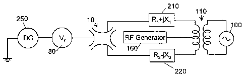
FIG. 2 is a schematic representation of a circuit used in the ion trap of the
present
invention.
FIG. 3 is a graph of two mass spectra obtained under identical conditions
using a
symmetrical trapping field and an asymmetrical trapping field.
FIG. 4 is a graph of four mass spectra showing the results obtained using four
different
scanning techniques.
DETAILED DESCRIPTION
Apparatus of the type which may be used in performing the method of the
present
invention is shown in FIG. I. Most of what is depicted in FIG. 1 is well known
in the art, and
2193655
9
need not be explained in detail. Ion trap 10, shown schematically in cross-
section, comprises a
ring electrode 20 coaxially aligned with upper and lower end cap electrodes 30
and 35,
respectively. These electrodes define an interior trapping volume. Preferably,
end cap
electrodes 30 and 35 have inner surfaces with a cross-sectional shape which is
"stretched." As
used herein the term "stretched," when referring to the end cap electrodes,
means electrodes
which have the ideal hyperbolic shape, as taught by Paul, et al., but which
are displaced from
their ideal separation along the z-axis to induce higher order field
components. The z-axis
displacement is equal for each electrode, such that only even order multipole
(e.g., octopole, etc.)
field components are introduced. Those skilled in the art will appreciate that
other techniques
may also be used to introduce higher order field components, such as changing
the shape of the
electrode surfaces to depart from the ideal hyperbolic. For example, shapes
which are more
convex than hyperbolic may be used. It is also known that shapes which are not
ideal, for
example, electrodes having a cross-section forming an arc of a circle, may
also be used to create
trapping fields that are adequate for many purposes. Moreover, by using end
caps which are the
same, but which are not equally displaced, or which have different shapes, one
can introduce odd
order (e.g., hexapole) field components will be added. As described, the
preferred stretched=erid
cap electrodes introduce only even order higher order field components. The
design and
construction of ion trap mass spectrometers are well-known to those skilled in
the art and need
not be described in detail. A commercial model ion trap of the type described
herein is sold by
the assignee hereof under the model designation "Saturn."
Sample, for example from gas chromatograph ("GC") 40, is introduced into the
ion trap
10. Since GCs typically operate at atmospheric pressure while ion traps
operate at greatly
reduced pressures, pressure reducing means (e.g., a vacuum pump and
appropriate valves, etc., .
not shown).are required. Such pressure reducing means are conventional and
well known to
those skilled in the art. While the present invention is described using a GC
as a sample source,
the source of the sample is not considered a part of the invention and there
is no intent to limit
the invention to use with gas chromatographs. Other sample sources, such as,
for example,
liquid chromatographs ("LCs") with specialized interfaces, may also be used.
For some
2~.9~~55
applications, no sample separation is required, and sample gas may be
introduced directly into
the ion trap.
A source of reagent gas (not shown) may also be connected to the ion trap for
conducting
chemical ionization ("CI") experiments. Sample (and optionally reagent) gas
that is introduced
into the interior of ion trap 10 may be ionized by using a beam of electrons,
such as from a
thermionic filament 60 powered by filament power supply 65, and controlled by
a gate electrode
70, which, in turn is controlled by the master computer controller 120. The
center of upper end
cap electrode 30 is perforated (not shown) to allow the electron beam
generated by filament 60
to enter the interior of the trap. When gated "on" the electron beam enters
the trap where it
collides with sample and, if applicable, reagent molecules within the trap,
thereby ionizing them.
Electron impact ionization ("EI") of sample and reagent gases is also a well-
known process that
need not be described in greater detail. Of course, the method of the present
invention is not
limited to the use of electron beam ionization within the trap volume.
Numerous other ionization
methods are also well known in the art. For purposes of the present invention,
the ionization
technique used to introduce sample ions into the trap is generally
unimportant. -- --
Although not shown, more than one source of reagent gas may be connected to
the ion
trap to allow experiments using different reagent ions, or to use one reagent
gas as a source of
precursor ions to chemically ionize another reagent gas. In addition, a
background gas is
typically introduced into the ion trap to dampen oscillations of trapped ions.
Such a gas may
also be used for collisionally induced dissociation of ions, and preferably
comprises a species,
such as helium, with a high ionization potential, i.e., above the energy of
the electron beam or
other ionizing source. When using an ion trap with a GC, helium is preferably
also used as the
GC carrier gas.
A trapping field is created by the application of an RF voltage having a
desired frequency
and amplitude to stably trap ions within a desired range of masses. RF
generator 80 is used to
create this field, and is applied to ring electrode 20. The operation of RF
generator 80 is,
preferably, under the control of computer controller 120. A DC voltage source
250 (shown in
2?9~b55
11
FIG. 2) may also be used to apply a DC component to the trapping field as is
well known in the
art. However, in the preferred embodiment, no DC component is used in the
trapping field.
Computer controller 120 may comprise a computer system including standard
features
such as a central processing unit, volatile and non-volatile memory,
input/output (I/O) devices,
digital-to-analog and analog-to-digital converters (DACs and ADCs), digital
signal processors
and the like. In addition, system software for implementing the control
functions and the
instructions from the system operator may be incorporated into non-volatile
memory and loaded
into the system during operation. These features are all considered to be
standard and do not
require fi~rther discussion as they are not considered to be central to the
present invention.
As is explained in greater detail hereinafter, periodically ions are scanned
out of ion trap
to produce a mass spectrum of the contents of the trap. Such scanning may be
performed
routinely, for example, to continuously monitor the substances present in the
outflow from GC
40,,or may be performed after an experiment is conducted in the ion trap, such
as an MS/MS
manipulation. According to the present invention, ions are scanned out of the
trap in sequential
mass order and are detected by an external detector such as electron
multiplier 90, which is also
subject to the control of computer controller 120. The output from electron
multiplier 90 is
amplified by amplifier 130, and the signal from amplifier 130 is stored and
processed by signal
output store and sum circuitry 140. Data from signal. output store and sum
circuitry 140 is, in
turn, processed by 1/O process control card 150. As noted above, UO card 150,
is controlled by
computer controller 120. The details of how components 90, 130, 140 and 150
operate are well
known and need not be described in further detail.
The supplemental dipole voltages) used in the ion trap may be created by a
supplemental
waveform generator 100, coupled to the end cap electrodes 30, 35 by
transformer 110.
Supplemental wavefor-m generator 100 is of the type which is not only capable
of generating a
single supplemental frequency component for dipolar resonance excitation of a
single species,
but is also capable of generating a voltage waveforrn comprising of a wide
range of discrete
frequency components. Any suitable arbitrary waveforrn generator, subject to
the control of
2198u55
12
controller 120, may be used to create the supplemental waveforms used in the
present invention.
According to the present invention, a multifrequency supplemental waveform
created by
generator 100 is applied to the end cap electrodes of the ion trap, while the
trapping field is
modulated, so as to simultaneously resonantly eject multiple ion masses from
the trap, as in an
ion isolation procedure. A method of generating a supplemental signal for
isolating selected ion
species is described in detail below. Supplemental waveform generator 100 may
also be used to
create a low-voltage resonance signal to fragment parent ions in the trap by
CID, as is well
known in the art.
As with most any instrument of its type, it is known that the dynamic range of
an ion trap
is limited, and that the most accurate and useful results are attained when
the trap is filled with
the optimal number of ions. If too few ions are present in the trap,
sensitivity is low and peaks
may be overwhelmed by noise. If too many ions are present in the trap, space
charge effects can
significantly distort the trapping field, and peak resolution can suffer. The
prior art has
addressed this problem by using a so-called automatic gain control (AGC)
technique which aims
to keep the total charge in the trap at a constant level. In particular, prior
art AGC techniques-
use a fast "prescan" of the trap to estimate the charge present in the trap,
and then use this
prescan to control a subsequent analytical scan. According to the present
invention, a prescan
may also be used to control space charge and optimize the contents of the trap
for an analytical
scan. Alternately, the technique described in co-assigned U.S. Pat. No.
5,479,012 may be used
to control space charge.
According to the present invention, an asymmetrical trapping field is
employed.
Preferably, the trapping field is constructed from a combination of dipole and
quadrupole
components all having the same frequency f. In addition, if stretched end cap
electrodes are
used, higher order field components (e.g., octopole) are inherently introduced
into the trapping
field. Further, as described below, the "dipole" component of the trapping
field inherently
causes higher order odd order field component to be present in the trapping
field, the
predominant one being a hexapolar component. The asymmetrical trapping field
used in
accordance with the present invention has a center which is displaced from the
mechanical center
CA 02198655 2000-06-27
13
of the ion trap, (as defined by the electrode geometry).
This is described in greater detail in coassigned U.S.
Patent No. 5,291,017, to Wang, et al. As noted, a damping
gas is used in this ion trap and the collisionally damped
trapped ions become positioned near and orbit about the
center of the trapping field after ionization is
completed. The inventors have determined that the secular
frequencies of the: ions trapped in an asymmetrical field
are substantially the Name as if they were trapped in a
symmetrical field, but that the centers of the orbits are
displaced in the axial direction.
As used herein, and as is commonly among those
skilled in the art, the term "dipole voltage" refers to an
AC voltage applied across the end cap electrodes of the
ion trap, such i:hat one end cap receives a positive
potential while th.e opposing end cap receives a negative
potential of equal magnitude, (the potentials being
relative to each other). More precisely, however, since
the end caps are not parallel plates, the resultant field
is not a pure dipole field, and inherently has higher
order field components. As described below, one of the
higher order field components is a hexapolar field which
is used, in accordance with a preferred embodiment, to
help excite ions out of the trap during mass scanning.
In the preferred embodiment, the dipole component
of the asymmetrical. rf trapping field is passively created
by using unequal lumped parameter impedances 210, 220 as
shown in FIG. 2. This technique for generating the
different components of the trapping field results in the
components all having the same relative phase. The dipole
component must be ~~onsidered as being part of the trapping
field as it has the same frequency and relative phase as
the quadrupole tramping voltage. It is further noted that
none of the trapped ions have secular frequencies which
are the same as the frequency f of the trapping voltage.
Therefore, the additional. dipole trapping field component
CA 02198655 2000-06-27
13a
does not contribute to the ejection of ions by resonant
excitation. AlternativE:ly, a supplemental dipole voltage
generator 100 may be used to actively create a dipole
component of the trapping field. In such an embodiment,
the phase of the :cupplernental dipole should be controlled
to be the same as the quadrupole component. In yet
another variation, both passive and active dipole
components may be: added to the trapping field. These
latter embodiments
21._98b55
14
permit variation in the ratio between the voltage of the dipole and quadrupole
components for
both the trapping field and the excitation field.
Briefly, the impedances which-are used to create the dipole take into account
the
capacitances between the end cap and ring electrodes ("C«"), the capacitances
between the end
electrodes and ground ("C~g"), and impedances 210 and 220 as shown in FIG. 2.
In commercial
ion traps, with mirrored symmetry (i.e., the end cap electrodes are the same
shape and same
displacement along the z-axis); Crc, = C,~2 and C,~ « C~g. The dipole is
created by the large and
equal current flowing from trapping field rf generator 80 through Crcl and
C,~z. This current also
flows through impedances 210 and 220 to create unequal voltage drops thereby
causing different
voltages to be applied to the two end caps, and thereby causing a dipole
voltage across the end
caps. The supplemental (excitation) field dipole is created by the voltage
divider action of
impedance 210 and C~gl as to the first end cap electrode 30 and the voltage
and by the voltage
divider action of impedance 220 and C~ as to the second end cap electrode 35.
A dipole voltage
is created when the two voltage divider ratios are unequal. Since the value of
C~ is largely set
by the mechanical design of the ion trap, additional impedances Z~ (not shown)
may be added to
provide an extra degree of freedom. The determination of the impedance values
of Z~, and 210
and 220 may be done by standard electrical engineering analysis and synthesis
techniques known
to those skilled in the art. According to the preferred embodiment of the
present invention the
quadrupole component of the trapping field is created by the ring electrode,
whereas the
quadrupole component of the excitation field is created by the end cap
electrodes. In addition,
the trapping and excitation fields operate at different frequencies. Thus,
impedances in the
system, discussed above, operate differently on the voltages used to create
the various field
components. By appropriately choosing the values of the impedances added to
the system, one
can vary the relative proportion of quadrupole and dipole components in the
fields. For,
example, by appropriate selection, it is possible to create a trapping field
with a significant
dipole component, while creating an excitation field with little or no dipole
component.
While the present invention is described using voltage generators applied
either to the
ring electrode and/or across the end cap electrodes, it will be apparent to
those skilled in the art
2198655
that independent voltage sources can be applied to each of the three
electrodes in the trap. Such
voltage sources could, for example, be arbitrary waveform generators under the
controlled of
computer controller 120.
The effect of the using an asymmetrical trapping field of the present
invention is to
greatly increase the percentage of ions, ejected from the ion trap during a
scanning operation,
which are directed to the detector.. As noted above, when scanning using prior
art symmetrical
trapping fields, approximately half of the ions leave the trap in each axial
direction. In addition,
it has recently been discovered that the asymmetrical trapping field of the
present invention
causes positive and negative ions to be separated from each other, thereby
obviating peak
artifacts associated with scanning negative ions with sufficient energy to
overcome the bias
voltage of the electron multiplier. Such unwanted peak artifacts due to
negative ions are
common when scanning using a symmetrical trapping field.
In its basidform the present invention uses an excitation field for ion
ejection comprising
a weak supplemental quadrupole field which is centered at the mechanical
center of the ion Trap:
As shown in FIGS. 1 and 2, the quadrupole excitation field is created by
applying the signal
from supplemental voltage generator 160 to the center tap of the secondary
coil of transformer
110. In this manner, the supplemental quadrupole excitation field is applied
to the end cap
electrodes so that this voltage signal does not interfere with the high-Q
circuit used to apply the
quadrupole trapping voltage to the ring electrode. Therefore, the center of
the trapping field and
the center of the weak supplemental excitation field are displaced from each
other. This enables
the supplemental quadrupole field to act on the trapped ions, since the
supplemental quadrupole
field is non-zero at the center of the trapping field. As used in the present
specification, the term
"weak supplemental quadrupole field" means that the field is not strong enough
to independently
trap a measurable number of ions. According to the preferred embodiment of the
present
invention, the frequency w of the supplemental quadrupole excitation field is
set at two-thirds
(z/s) of the trapping field frequency, i.e., w/f= 2/s.
:2198655
16
It is sometimes helpfirl to consider that the asymmetrical trapping field and
the
supplemental excitation field (which may include additional components as
described below) act
on ions within the trap as a single combined field. According to the present
invention, one of the
characteristics of this combined field is then scanned to bring ions into
resonance with the
supplemental excitation field in sequential mass order, thereby ejecting them
from the ion trap
for detection. Preferably, the voltage of the quadrupole component of the
trapping field is
scanned (i.e., linearly increased) to perform the mass scan. Other techniques
for scanning the
combined field are known to those skilled in the art and could also be used.
However, such
techniques are often more complicated and, therefore, .less preferred. In
addition, it is preferred
to maintain the two-thirds relationship between the frequency f of the
trapping voltage and the
frequency w of the excitation voltage, and, therefore frequency scanning is
also not preferred for
this reason.
In U.S. Patent No. 3,065,640, Langmuir taught that a supplemental quadrupole
field with
a frequency wP will have quadrupole axial parametric resonances that are
related to the axial
secular frequencies wZ by the equation wp = 2wz(N where N is a positive
integer. Thus, the--'
parametric frequencies are always less than or equal to twice one of the
secular frequencies. It
was also shown that a quadrupole~ excitation field at these frequencies will
result in the
exponential growth of axial oscillation. However, in the past, a limitation on
the use of
quadrupole .excitation has been the fact that a quadrupole (or higher order)
excitation field is zero
at the center of the field. In the prior art, use of a quadrupole excitation
field has been limited to
symmetrical trapping fields, such that the center of the trapping field and
the center of the
excitation field where both at the mechanical center of the ion trap. Various
techniques have
been proposed to overcome this limitation, including using a dipole excitation
field to move ions
away from the center of the trapping field where they can be acted upon by the
quadrupole
excitation field, or using a very strong quadrupole excitation field, i.e., a
supplemental
quadrupole field which is strong enough to act as a trapping field. These
solutions have not been
satisfactory.
2i~~555
17
According to the present invention, the center of the quadrupole excitation
field does not
coincide with the center of the asymmetrical trapping field. Thus, a weak
quadrupole excitation
field is able to act directly on the ions trapped in the asymmetrical trapping
field because the ions
are trapped in a region of the excitation field which is non-zero.
Accordingly, the ions will be
ejected from the ion trap by resonant excitation without the need to use a
supplemental dipole
field. In the preferred embodiment, ions are sequentially brought into
resonance with the
supplemental excitation field by increasing the amplitude of the trapping
field which, in turn,
changes the respective resonant frequencies of the trapped ions.
Preferably, the supplemental excitation voltage also includes a dipole
component in
addition to the quadrupole component. This additional dipole component should
have the same
frequency w as the quadrupole excitation field, preferably two-thirds of the
trapping field
frequency. The-supplemental dipole component of the excitation field can be
created in the same
manner as the corresponding component of the trapping field, e.g., using
unequal lumped
parameter impedances 210 and 220, and/or using a phase locked active dipole
voltage generator
100. , '-
Again, the passive approach has the advantage. of easily assuring that the
various field
components have the same relative phase and reduced hardware requirements. The
supplemental
dipole field may be weak, such that it would not, acting alone, be capable of
ejecting ions from
the ion trap. Mass resolution is enhanced by minimizing all of the excitation
field components,
including the dipole field.
It is well-known that the axial secular frequencies of the trapped ions have
values
wN= (2N+(3)f/2 where N is an integer and (i is related to the operating point
of the trap.
Previously, spectroscopists have used N = 0 because the coupling coefficient
is greatest for this
value of N. (As the absolute value of N increases, the coupling coefficient
decreases.) Thus,
previously, there has been no recognized advantage for using a value of N
other than 0. The
present invention uses N = -1 to gain a heretofore unrecognized advantage. By
way of example,
assume that f = 1050 kHz and wP= 700 kHz. If the fundamental secular frequency
(i.e.,. N = 0) is
219~~55
18
used to excite the parametric oscillation, then it would be at 350 kHz and
would require an
additional rf generator. However, if p = 2/s is selected as the operating
point, the N = -1
harmonic of the secular motion would be at 700 kHz and, thus, a quadrupole
field at this
frequency would also act to excite the parametric oscillation. Thus, the
selection of this
combination of operating points and frequencies eliminates the need for an
additional rf
generator. In addition, this combination permits phase locking of the trapping
field and the
excitation field in a simple manner since the frequencies of the two fields
have an integer
relationship. Likewise, the trapping field dipole and the supplementary
excitation field dipole
can easily be phase locked while still using passive components, as described
in connection with
FIG. 2. Finally, the technique of the present invention allows a linear
increase in the
supplemental quadrupole strength and dipole strength, e.g., respective
voltages applied to the end
caps, while maintaining a constant ratio between them, as the amplitude of the
trapping voltage
is increased during a scan. It can be shown from the equations of motion that
it is advantageous
to maintain a constant ratio between the excitation voltage and the trapping
voltage.
Specifically, as recognized by the inventors hereof when an asymmetrical
trapping field is used
in conjunction with a quadrupole excitation field, such that trapped ions are
displaced from tlie-
center of the ion trap, the degree of excitation of ions is mass dependent.
Specifically, as taught
herein in connection with the preferred embodiment, there should be a constant
ratio maintained .
between the field strengths of the dipole and quadrupole components of the
trapping field
scanning the trap in order for ion displacement to be independent of mass.
This is not
recognized in the prior art.
As described above, when a dipole voltage is applied to end caps electrodes,
higher odd
order field components are also created, the predominant added field
cori~ponent being a
hexapolar field. It can be shown that when using an operating point of (i =
z/3 ions are also in
resonance with the hexapolar component of the trapping field. As will be
appreciated, the
magnitude of the hexapolar field is a firnction of the magnitude of the dipole
component of the
trapping field. When using low dipole voltages, e.g., less than.about 5%
relative to the
quadrupole voltage, then the hexapole component is too small to significantly
affect the ejection
process. However, when using a stronger dipole trapping field component,
greater than 5% or,
2i9~u55
., .: .. J
19
preferably greater than 10% of the quadrupole trapping voltage, then the
hexapole component is
significant and contributes to ion ejection when (3 = 2/3. In accordance with
the present
invention, the assistance in ejecting ions caused by this added field
component appreciably
improves mass resolution when scanning the ion trap and increases the fraction
of ions that are
ejected in a desired direction.
While the use of hexapole fields is known in the prior art, such prior art
fields have been
created by shaping the electrodes of the ion trap. These mechanical methods of
creating
hexapole fields have a number of limitations which are overcome by the
electrical technique of
the present invention. When mechanical means are used to form a hexapole
field, the relative
position or "polarity" of the field is fixed. In contrast, when the hexapole
field component is
created electrically, its polarity or relative position can be reversed or
otherwise modified by
changing the relative phase of the quadrupole and dipole components of the
trapping field. This
can be important since the behavior of positive and negative ions in the
trapping field is affected
differently by a trapping field having a hexapole component. Depending on
whether one is
experimenting on positive or negative ions, one: may want to reverse the
polarity of the hexapole
field component. Moreover, according to the present invention, it is possible
to employ a
symmetrical trapping field during the ion formation stage of an experiment and
then apply an
asymmetrical trapping field afterwards. During. ion formation, ions tend to be
distributed
throughout the entire volume of the ion trap, and ions which are not near the
center are subject to
ejection due to the resonance with the hexapole field. After the ions are
thermalized or_damped
to the center of the ion trap they are no longer susceptible to unwanted
resonant ejection in this
manner. Finally, the relative proportion of the hexapole and quadrupole
components of the
trapping field is fixed in a mechanical system, whereas the proportion can be
varied, if desired,
when the hexapole field is generated electrically.
By using a set integer ratio between f and c.~, as in the present invention,
it is possible to
assure phase locking between the trapping voltages and the excitation
voltages, thereby
eliminating the effects of frequency beating. It is particularly advantageous
to utilize the
smallest possible integer ratio between these frequencies (e.g., 2:3)
consistent with the other
2'198655
objects of the invention, because the advantages of phase locking will occur
(and be repeated) in
the smallest number of cycles. Phase lock circuitry 170, of the type which is
well known in the
art, is used to lock the phases of the voltages created by the trapping field
generator 80 and the
supplemental excitation field generator 160. When using a supplemental dipole
excitation
source, e.g., voltage source 100 in FIG. 1, an additional phase lock circuitry
175 is, preferably
also used.
For the case of a symmetrical trapping field of the prior art, ions having a
center of
oscillation at the geometric center of the trap initially experience very
little effect from a
substantially quadrupole excitation applied symmetrically from the end caps,
because the
thermalized ions are trapped in a region of approximately null field. It is
known to apply an
excitation filed having both dipole and quadrupole components whereby the
trapped ions are
first affected by the dipole component. Power is promptly absorbed from the
dipole resonance
and the resonantly mass selected ions are subject to greater axial amplitude
oscillation. Aa a
result of the greater axial amplitude, these ions then absorb power from the
mass selective
resonant quadrupole field component. This sequential process, governing the
symmetric
arrangement of prior art is to be contrasted with the present invention
wherein the mass
independent center of oscillation of the trapping field is displaced from the
central region of the I
mass selective combined dipole quadrupole excitation field. See patent
5,347,127 to Franzen
where the sequential nature of the prior art is deliberately emphasized.
FIG. 3 compares the method of the peesent invention, i.e., using an
asymmetrical trapping
field, with the same method but using a symmetrical trapping field, as
discussed above. The
mass scan on the left side of FIG. 3, curve 310, was acquired used the method
of the present
invention, while the mass scan on the right side of FIG. 3, curve 320, was
acquired using a
symmetrical trapping field. In both instances, the supplemental excitation
field comprised a
quadrupole voltage and a dipole voltage of the same phase. It is apparent that
the asymmetrical
trapping field of the present invention, combined with a excitation voltage
comprising
quadnrpole and dipole components, produces a higher intrinsic rate of ion
ejection with a
resulting better resolution and peak intensity. From a qualitative point of
view the present
invention provides a concurrent effect of both quadrupole and dipole
excitation components
219655
21
rather than the sequential effect of the prior art because the relative
displacement of the center of
ion density is achieved by the asymmetrical trapping field. Accordingly, the
mass selected ions
are ejected promptly in time. For a given scan rate this clearly results in a
more precise mass
resolution than would be achievable for a less rapid ejection rate.
FIG. 4 compares various scanning techniques. The mass scan 410 is the prior
art
resonant ejection technique using a dipole excitation voltage in a symmetrical
trapping field. As
described above, the frequency of the excitation voltage (w, = 485 kHz) is set
at about one half
of the trapping field frequency (f = 1050 kHz) as taught in the prior art.
Noticeable distortions in
the mass peak may be observed due to frequency beating. Mass scan 420 is taken
under
identical conditions using the asymmetrical trapping field of Wang, et al.
While the height of
the peak is higher due to the fact that ions are preferentially ejected
towards the detector, the
mass resolution is substantially the same. The effects of frequency beating
are, again,
noticeable. Mass scan 430 uses a symmetrical trapping field and an excitation
voltage
comprising both quadrupole and dipole components at a frequency (wd = wq = 700
kHz) which
is set at two-thirds of the trapping field frequency, f = 1050 kHz. In curve
430 there is no -_- .:
noticeable frequency beating, and the mass resolution is slightly improved
over scans 410 and
420. Finally, scan 440, according to the preferred embodiment of present
invention, was taken
under identical conditions as scan 430, but using an asymmetrical trapping
field. Note that the
mass resolution is greatly improved over any of the other scans, there is no
noticeable frequency
beating, and the peak height is far better than the other scans.
It is specifically recognized that the displacement of the center of
oscillation of ions by
the trapping field from the central region of the excitatiowfield facilitates
manipulation of
trapped ion populations generally. By way of example, ion isolation procedures
yield improved
result because the simultaneous absorption of power from dipole and quadrupole
fields (in
contrast to sequential resonant absorption) allows for a more rapid mass
selected ion ejection.
The time spent in exciting masses greater than, and less than a selected mass
is therefore
minimized. The selected mass, which may be inherently unstable or which is
subject to
dissociation, is therefore available for a greater time interval for isolated
ion processes.
219865
22
References herein to the excitation field are not limited to an excitation
Geld
characterized by a single discrete frequency. Broadband excitation comprising
a plurality of
frequency components is well known for the purpose of providing excitation to
a selected range,
or ranges of ion mass. The selection and phasing of the frequency components
of the broad band
waveform are well known in the art. Each such frequency component herein
contains
quadrupolar and preferably both quadrupolar and dipolar multipo(arity.
While the present invention has been described in connection with the
preferred
embodiments thereof, those skilled in the art will recognize other variations
and equivalents to
the subject matter described. Therefore, it is intended that the scope of the
invention be limited
only by the appended claims.