Language selection

Search

Patent 2199050 Summary

Third-party information liability

Some of the information on this Web page has been provided by external sources. The Government of Canada is not responsible for the accuracy, reliability or currency of the information supplied by external sources. Users wishing to rely upon this information should consult directly with the source of the information. Content provided by external sources is not subject to official languages, privacy and accessibility requirements.

Claims and Abstract availability

Any discrepancies in the text and image of the Claims and Abstract are due to differing posting times. Text of the Claims and Abstract are posted:

  • At the time the application is open to public inspection;
  • At the time of issue of the patent (grant).
(12) Patent: (11) CA 2199050
(54) English Title: DOWN PRESSURE SYSTEM WITH FREE FLOAT EXTENSION
(54) French Title: DISPOSITIF D'ENFONCEMENT A RALLONGE DE PLANAGE LIBRE
Status: Expired
Bibliographic Data
(51) International Patent Classification (IPC):
  • A01B 5/06 (2006.01)
  • A01C 5/06 (2006.01)
  • A01C 7/20 (2006.01)
(72) Inventors :
  • WODRICH, TIMOTHY DIRK (United States of America)
  • STANFILL, RALPH EVERETTE (United States of America)
(73) Owners :
  • DEERE & COMPANY (United States of America)
(71) Applicants :
  • DEERE & COMPANY (United States of America)
(74) Agent: BORDEN LADNER GERVAIS LLP
(74) Associate agent:
(45) Issued: 2001-02-20
(22) Filed Date: 1997-03-03
(41) Open to Public Inspection: 1998-02-01
Examination requested: 1997-03-03
Availability of licence: N/A
(25) Language of filing: English

Patent Cooperation Treaty (PCT): No

(30) Application Priority Data:
Application No. Country/Territory Date
08/691,105 United States of America 1996-08-01

Abstracts

English Abstract


An opener for use in varying ground conditions, ranging from no-till to conventional
full tillage conditions, includes an adjustable down pressure control and a down pressure
spring and tension link assembly which selectively provide a limited free float opener
condition or a conventional down pressure spring controlled bias condition. A sleeve
slidably received by the opener arm and mounted over the lower portion of the tension link
assembly allows the opener to free float in loose soil conditions so that only the weight of
the opener provides downward bias when the down pressure control is adjusted to a
minimum condition. The opener is free to ride up and down to follow irregularities in the
ground surface. In harder soil conditions such as those encountered in no-till farming
methods, the down pressure control is adjusted to a position wherein an enlarged portion
on the sleeve bottoms against the opener arm and the spring begins to compress so that
the opener operates in the conventional spring biased mode. The sleeve allows increased
downward movement of the opener to follow depressions in the soil.


French Abstract

Cette invention concerne un ouvreur de sillon adapté à des conditions de sol variables, allant de sols non labourés aux sols travaillés à fond. Il comprend une commande réglable de pression d'enfoncement et un mécanisme d'enfoncement à ressort et tendeur qui autorisent un planage libre limité ou un travail classique en profondeur contrôlé par ressort d'enfoncement. Un manchon monté en ajustement libre sur le bras de l'ouvreur de sillon et s'étendant jusqu'à couvrir la partie inférieure du tendeur permet à l'outil objet de l'invention de planer librement en sols meubles de telle sorte que le seul poids de l'ouvreur détermine la profondeur de creusage, le réglage de pression d'enfoncement étant au minimum. L'ouvreur peut alors suivre les ondulations du sol. En sol plus dur comme ceux rencontrés en cultures sans labour, la commande de pression d'enfoncement est réglée à une position où une partie élargie du manchon prend appui sur le bras de l'ouvreur et le ressort commence à appuyer sur l'ouvreur selon le mode classique. Le manchon permet un mouvement vertical de plus grande amplitude pour suivre les dépressions dans le sol.

Claims

Note: Claims are shown in the official language in which they were submitted.


The embodiments of the invention in which an exclusive property or privilege
is
claimed are defined as follows:
1. In an implement having a frame adapted for forward movement over the
ground,
an opener assembly having an opener arm rockably connected to the frame for
vertical
movement with respect to the frame and a rearward end connected to a furrow
opener for
providing a furrow in the ground, a down pressure system for adjustably
biasing the opener
arm, the down pressure system comprising:
a coil spring having first and second abutment portions;
a tension link extending through the coil spring and having first and second
ends;
a pressure adjusting mechanism connected between the frame and the coil
spring;
and
a lost motion connection extending between the second end of the tension link
and
the furrow opener arm, the lost motion connection providing a limited downward
bias on
the opener independent of the coil spring over a first range of vertical
movement of the
furrow opener arm and a spring-dependent downward bias on the opener over a
second
range of vertical movement of the opener arm.
2. The down pressure system as set forth in claim 1 wherein the lost motion
connection comprises a member slidably received by the opener arm.
3. The down pressure system as set forth in claim 2 wherein the member is
connected to the second end of the tension link and includes an enlarged
section
positioned adjacent the second abutment portion.
4. The down pressure system as set forth in claim 2 wherein the member
comprises a first portion of preselected cross-section projecting through the
opener arm
and a second portion of cross-section larger than that of the first portion
and abutting the
second abutment portion of the spring.
5. The down pressure system as set forth in claim 4 wherein the first portion
slides
freely through the opener arm in the first range of vertical movement, the
first range of
vertical movement defining a limit position wherein the opener arm contacts
the second
portion.
6. The down pressure system as set forth in claim 2 wherein the tension link
comprises an adjustable length member including a bolt projecting downwardly
through the
opener arm and having a lower enlarged head portion limiting downward rocking
of the
opener arm to a lowermost position, wherein the lowermost position is
dependent upon
length of the adjustable length member.
7. The down pressure system as set forth in claim 2 wherein the tension link
compresses the coil spring and defines an initial spring compression, and the
downward


bias in a preselected limit position in the second range is dependent on the
initial spring
compression.
8. The down pressure system as set forth in claim 7 wherein the tension link
includes an adjustable length member for varying the initial spring
compression.
9. The down pressure system as set forth in claim 1 wherein the opener has a
preselected weight and, when the opener arm is in the first range of vertical
movement,
substantially all of the downward bias is dependent upon the preselected
weight.
10. The down pressure system as set forth in claim 9 wherein the downward bias
in
the second range is dependent upon the preselected weight and the compression
of the
spring and is at least 30% greater than the downward bias in the first range.
11. In an agricultural implement having a frame adapted for forward movement
over
the ground, the implement including an opener tool assembly with an arm having
a first
end pivotally connected to the frame for rocking of the arm about a transverse
horizontal
axis and a second end supporting an earthworking tool, down pressure structure
for
biasing the tool into the ground with varying down pressure, the down pressure
structure
comprising:
a tension link;
a receiving portion connected to the arm and supporting the tension link;
a movable down pressure control connected to the tension link;
a compression spring supported by the tension link between the receiving
portion
and the down pressure control;
the down pressure control movable relative to the arm over a first range of
positions relative to the arm wherein the compression spring is offset from
the receiving
portion so the arm is free to pivot about the axis independently of the
compression spring
and over a second range of positions wherein the compression spring abuts the
receiving
portion and biases the arm about the axis, the bias of the spring dependent
upon the
position of the down pressure control in the second range.
12. The down pressure structure as set forth in claim 11 wherein the tension
link is
slidably received by the receiving portion and the compression spring has a
precompressed length less than the length of the tension link.
13. The down pressure structure as set forth in claim 12 wherein, in the first
range
of positions, the arm is in a free float condition wherein down pressure on
the tool is
provided substantially by weight of the opener tool assembly.
14. The down pressure structure as set forth in claim 13 wherein the down
pressure
control, when in the second range of positions relative to the arm, provides a
minimum


vertical bias which differs by at least 30% from a bias provided when the arm
is in the free
float condition.
15. In an agricultural implement with a frame and including a conservation
opener
having an earthworking tool supported from an aft end of an arm, the arm
having a forward
end connected for pivoting relative to the frame, a two-stage down pressure
arrangement
for providing a first stage of down pressure on the opener for operation in
first ground
conditions and a second stage of down pressure lower than the first stage of
down
pressure for operation of the opener in ground conditions wherein the ground
is looser
than in the first ground conditions, the down pressure arrangement comprising:
a spring assembly including a coil spring supported between the frame and the
arm;
a down pressure control connected to the spring assembly and movable relative
to
the arm to selectively move the spring assembly between biasing and non-
biasing
positions relative to the arm, wherein when the spring assembly is in the non-
biasing
position, the arm is free to pivot independently of the spring and when the
spring is in the
biasing position, the spring is compressed between the arm and the frame to
bias the arm
vertically.
16. The down pressure arrangement as set forth in claim 15 wherein the spring
assembly includes a tension link connected to the down pressure control and
supporting
the coil spring at a preselected spring length when the spring assembly is in
the non-
biasing position, the tension link including a lost motion connection portion
facilitating
motion of the arm relative to the frame when the spring assembly is in the non-
biasing
position.
17. The down pressure arrangement as set forth in claim 16 wherein the lost
motion connection portion includes a spring abutment member slidably received
by the
arm, the spring abutment member contacting the arm when the spring assembly is
moved
to the biasing position.
18. The down pressure arrangement as set forth in claim 16 wherein the lost
motion connection portion facilitates downward movement of the conservation
opener
when the spring assembly is in the non-biasing position so the opener can
follow
depressions and wheel tracks in the soil.
19. The down pressure arrangement as set forth in claim 16 wherein the lost
motion connection portion includes a sleeve slidably positioned in an aperture
in the arm,
and wherein the tension link further includes a bolt slidably received through
the sleeve
and projecting into the coil spring.


20. The down pressure arrangement as set forth in claim 15 wherein the spring
assembly includes a tension member extending through the coil spring and
retaining the
coil spring in a preselected compressed condition when the spring assembly is
in the
non-biasing position and a downwardly projecting portion slidably received by
the arm.

Description

Note: Descriptions are shown in the official language in which they were submitted.


21 q~O50

DOWN PRESSURE SYSTEM WITH FREE FLOAT EXTENSION
BACKGROUND OF INVENTION
1) Field of Invention
The present invention relates generally to agricultural implements such as
conservation openers, and more specifically to down pressure systems for such
implements.
2) Related Art
In recent years, no-till farming methods have been employed, and planting in soil
conditions where the ground has not been worked requires openers having down pressure
systems that can generate a relatively high down force for adequate ground penetration.
An example of such an opener is shown in U.S. Patent No. 4,760,806. This type ofopenér, commercially available on the John Deere 750 Grain Drill, has a down pressure
spring that starts to compress when a minimum force of approximately 225 pounds is
applied to the opener. A hydraulic control such as shown in U.S. Patent No. 5,065,681 is
connected to an opener rockshaft and provides an adjustable average down force on the
openers. The control can be adjusted so that the openers just come into contact with the
ground without compression of the down pressure springs.
For various reasons, operators that have switched to no-till farming methods will at
times be required to work the seed bed prior to seeding. In loosened soil conditions the
relatively high minimum force causes the opener to penetrate the soil too deeply. To
alleviate the over-penetration problem in tilled soil, the operator often reduces the
hydraulically adjustable down force applied to the opener rockshaft to the level at which
the openers just contact the ground and the down pressure springs do not yet compress.
As the drill passes over surface irregularities and undulations, each opener is able to rise
by compressing the spring but is unable to lower because of the limitations of the down
force system. When the drill passes over a depression which is within the width of the
drill, one or more of the openers are often unable to drop down a sufficient distance to
follow the depression and place the seed at the proper planting depth unless the down
force on the other openers is increased to a level above the optimum. At times, the seed
may actually be placed on the surface of the soil rather than in the ground. Also, an
opener which is following a wheel in tilled soil may be unable to lower a sufficient amount
to run in the wheel track depression, especially when the down force is set to the minimum
level.
BRIEF SUMMARY OF THE INVENTION
It is therefore an object of the present invention to provide an improved down
pressure system for use in implements such as conservation openers. It is another object

21 99050

to provide such a system which overcomes most or all of the above-listed disadvantages
of previously available down pressure system.
It is a further object to provide an improved down pressure system for a ground
working implement which alleviates depth control problems associated with a ground
5 working tools having to work in soils that range from previously worked loose soil
conditions to relatively hard no-till soil conditions. It is still another object to provide such a
system which allows the tools to follow ground irregularities and undulations and to run in
wheel tracks in the different soil conditions without over- or under-penetration of the tools
in the soil.
It is another object of the present invention to provide an opener down pressurestructure including an adjustable hydraulic down pressure control and down pressure
spring, wherein the control can be set to operate the opener in first and second down
pressure ranges, the down pressure in the first range being substantially less than the
second for operating in loose soil conditions without over-penetration or under-penetration,
even when the implement passes over depressions in the soil or the opener is riding in a
wheel track. It is a further object to provide such structure wherein in the first range the
down pressure is dependent substantially on opener weight alone and in the second range
the opener is biased downwardly by the down pressure spring and the opener weight.
It is another object to provide an improved down pressure spring arrangement foran earthworking tool mounted on a pivoting opener arm. it is a further object to provide
such an arrangement in combination with a hydraulic down pressure control to provide a
first down pressure range particularly suitable for tilled soil conditions and a second down
pressure range for harder minimum and no-till conditions.
It is a further object to provide an agricultural down pressure spring arrangement
having a lost motion connection between the down pressure spring and the tool supporting
arm to provide different ranges of down pressure operation for different soil conditions. It
is a further object to provide such an arrangement which facilitates proper depth of
operation with under low down pressure conditions, even when the tool is operating in a
tire track.
A grain drill opener assembly or similar spring biased ground working implement for
use in varying ground conditions, ranging from no-till to conventional full tillage conditions,
includes an adjustable down pressure control and a down pressure spring and tension link
assembly which selectively provide either a limited free float opener condition or a
conventional down pressure spring controlled bias condition. A sleeve slidably received by
the opener arm and mounted over the lower portion of the tension link assembly allows the


21 99050
opener to free float in loose soil conditions so that only the weight of the opener provides
downward bias when the down pressure control is adjusted to a minimum condition. The
opener is free to ride up and down to follow irregularities in the ground surface and to
operate at the proper depth in a wheel track or similar depression in the soil without having
to increase the average down pressure on the openers. In harder soil conditions such as
those encountered in no-till farming methods, the down pressure control is adjusted to a
position wherein the sleeve bottoms against the opener arm and the spring begins to
compress so that the opener operates in the conventional spring biased mode.
These and other objects, features and advantages of the present invention will
become apparent to one skilled in the art upon reading the following detailed description in
view of the drawings.
BRIEF DESCRIPTION OF THE DRAWINGS
Fig. 1 is a side view of a conventional grain drill opener assembly with a hydraulic
down pressure control and a down pressure spring.
Fig. 2 is a side view of an improved down pressure spring arrangement for an
opener showing the opener within a first range of positions for a relatively low downward
bias.
Fig. 3 is a side view similar to FIG. 2 but showing the spring arrangement partially
in section.
Fig. 4 is a view similar to FIG. 2 but showing the opener at the lower end of a
second range of positions wherein the down pressure spring is begins to provide
downward bias on the opener assembly.
DESCRIPTION OF THE PRIOR ART
Referring to Fig. 1, therein is shown a portion of an implement 6 with a main frame
8 adapted to be towed forwardly (F) over the surface of the ground by a tractor (not
shown). As shown, the implement 6 is a grain drill and includes a plurality of conventional
furrow opener assemblies 10 supported from a rockshaft 12 mounted on the frame 8.
Each furrow opener assembly 10 is generally of the type shown and described in the
aforementioned U.S. Patent No. 4,760,806 and U.S. Patent No. 5,092,255 and includes an
angled disk 18 supported from a drawbar 22 for rotation about an axis angled from the
transverse direction. A seed boot 24 is supported adjacent the disk 18 and is connected
to a metered source of seeds on the implement through a flexible seed tube 28. A down
pressure spring assembly 32 connected to an adjustable hydraulic down pressure control
34 adjustably biases the opener disk 18 into the soil to open a furrow 36. In addition to
opener lift and lower functions, the control 34 provides a generally constant average down


21 99050

pressure for the opener assemblies on the rockshaft 12 and preferably is of the type
shown and described in the aforementioned U.S. Patent No. 5,065,681.
A depth adjustment wheel 42 is supported for rotation adjacent the leading side of
the disk 18 about an axis offset from the axis of the disk. Furrow depth control is provided
5 by an adjustment mechanism 44 which moves the axis of the wheel 42 vertically with
respect to the disk. Firming and closing wheels 51 and 52 are supported rearwardly
adjacent the disk 18 from arms 53 and 54 and may be adjusted by down pressure spring
assemblies 55 and 56.
DESCRIPTION OF THE PREFERRED EMBODIMENT
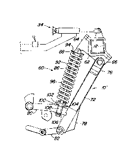
Referring to FIGS. 2 - 4, therein is shown a furrow opener assembly 10' having an
improved down pressure spring arrangement 60 that provides two-stage down pressure or
force capability for improved operation in varying soil conditions. In the first stage,
downward bias is independent of a down pressure spring and in the second stage aconventional spring-assisted, adjustable down pressure is provided.
The opener assembly 10' includes a bracket 62 attached to the rockshaft 12 and
having upper and lower rearwardly directed support portions 64 and 66. The rockshaft 12
with the bracket 62 is rockable about a transverse pivot by the hydraulic down pressure
control 34. A drawbar or arm 72 includes an upper rear portion 76 pivotally connected to
the support portion 66. The arm 72 extends downwardly and rearwardly to a lower tool
supporting end 78 for supporting conventional earth engaging tools such as shown in the
furrow opener assembly 10 of FIG. 1. The tool supporting end 78 includes an arm portion
80 projecting rearwardly from the arm 72 and a lower support 82 extending rearwardly
from the bottom of the arm 72. The aft end of the arm portion 80 supports firming and
closing wheels (not shown) similar to those shown at 51 and 52 in FIG. 1. An angled disk,
depth control wheel, and depth adjustment mechanism (not shown) similar to those shown
at 18, 42 and 44 in FIG. 1 are supported at the bottom of the arm 72 and on the lower
support 82.
The down pressure spring arrangement 60 includes a tension link indicated
generally at 86 having an upright casting 88 pivotally connected at its upper end to the
bracket support portion 64. A coil spring 92 encircles the casting 88 and abuts an upper
spring retaining member 94. The casting 88 includes an axially extending bore and a
lowermost nut capturing portion (FIG. 3) non-rotatably receiving a nut 98. The threaded
end of the bolt 96 is received by the nut 98 in the capturing portion and extends upwardly
into the casting bore.

21 99050

A sleeve member 100 including an enlarged spring abutting end 102 and a
cylindrical sleeve 104 is slidably supported on the lower headed end of the bolt 96 directly
above an enlarged washer 106. The sleeve 104 is slidably received within a bore 108
located in a receiving area of the arm portion 80. The length of the sleeve 104 is
5 substantially greater than the thickness of the arm portion so that the sleeve member 100
can slide freely in a vertical direction relative to the arm between a lowermost position
(FIG. 4) wherein the spring abutting end 102 bottoms on the top of the arm portion 80 and
an uppermost position (not shown) wherein the washer 106 contacts the bottom of the arm
portion 80.
The end 102 projects into the lower end of the spring 92 and retains the end on the
sleeve. The bolt 96 is threaded into the nut 98 to provide a preselected spring
compression. The arm 72 can pivot freely independently of any bias from the spring 92
until the arm reaches a pivotal position where the lower side of the enlarged end 102
contacts the top of the arm portion 80 (FIG. 4). Thereafter, any further rotation of the arm
72 upwardly causes the spring 92 to compress beyond the preselected spring compression
between the end 102 and the upper retaining member 94. The lower end of the bolt 96
will slide downwardly through the sleeve 104 as the spring 92 is compressed with upward
rotation of the arm 72 about the pivotal axis at 66. When the rockshaft 12 is rotated in the
clockwise direction to raise the opener assembly 10' from the ground, the enlarged washer
106 contacts the bottom of the arm portion 80, and the tension link 86 rotates the arm 72
upwardly to a transport position wherein any tools connected to the arm are offset a
substantial distance above the ground.
In operation, assuming that the operator is about to begin a planting operation in a
field that has loose soil conditions, the rockshaft 12 is rotated in the counterclockwise
direction by adjusting the down pressure control to a minimum level to extend the cylinder
until the opener assembly 10' just engages the ground and the sleeve assembly 100
passes through the position shown in FIGS. 2 and 3 to rest on the arm portion 80. At the
minimum down pressure setting of the control 34, the downward bias on the assembly is
substantially limited to that provided by the weight of the assembly. The arm 72 is free to
pivot up and down to follow the ground contour independently of any bias by the down
pressure spring 92 until the arm portion either bottoms on the washer 106 or contacts the
enlarged end 102 of the sleeve assembly 100 and begins to compress the spring. If for
any reason an individual opener assembly 10' encounters an obstacle, the arm 72 can
pivot upwardly beyond the non-biased free pivoting range as the end 102 which contacts
the arm portion 80 compresses the spring 92. However, the pressure control 34 will


21 99050

automatically maintain the rockshaft 12 in the position wherein the average operating
pressure of the opener assemblies is such that free pivoting of at least most of the
assemblies on the rockshaft is maintained. If the opener has to operate in a tire track or
has to move down in a depression in the soil, the sleeve assembly 100 helps assure that
5 the opener does not lift out of the soil.
If the operator encounters harder soil conditions, for example, those conditionstypical of minimum or no-till practices, he adjusts the pressure control 34 to rotate the
rockshaft 12 in the counterclockwise direction from the free pivot position to a position
wherein the enlarged end 102 bottoms on the arm portion 80 and the spring 92 begins to
10 compress. Thereafter, the opener assembly 10' operates in the conventional spring biased
mode wherein the down pressure on the opener assembly is the sum of the opener weight
and the bias provided by the spring 92. An average down pressure is maintained by the
control 34. Preferably, the minimum vertical bias provided in the conventional spring
biased mode is at least 30% greater than the bias provided when the arm is in the free
15 float condition.
Having described the preferred embodiment, it will be apparent that modifications
can be made without departing from the scope of the invention as set forth in the
accompanying claims.

Representative Drawing
A single figure which represents the drawing illustrating the invention.
Administrative Status

For a clearer understanding of the status of the application/patent presented on this page, the site Disclaimer , as well as the definitions for Patent , Administrative Status , Maintenance Fee  and Payment History  should be consulted.

Administrative Status

Title Date
Forecasted Issue Date 2001-02-20
(22) Filed 1997-03-03
Examination Requested 1997-03-03
(41) Open to Public Inspection 1998-02-01
(45) Issued 2001-02-20
Expired 2017-03-03

Abandonment History

There is no abandonment history.

Payment History

Fee Type Anniversary Year Due Date Amount Paid Paid Date
Request for Examination $400.00 1997-03-03
Registration of a document - section 124 $100.00 1997-03-03
Application Fee $300.00 1997-03-03
Maintenance Fee - Application - New Act 2 1999-03-03 $100.00 1999-03-02
Maintenance Fee - Application - New Act 3 2000-03-03 $100.00 2000-03-02
Final Fee $300.00 2000-11-17
Maintenance Fee - Patent - New Act 4 2001-03-05 $100.00 2001-03-02
Maintenance Fee - Patent - New Act 5 2002-03-04 $150.00 2002-03-01
Maintenance Fee - Patent - New Act 6 2003-03-03 $150.00 2003-02-28
Maintenance Fee - Patent - New Act 7 2004-03-03 $200.00 2004-02-20
Maintenance Fee - Patent - New Act 8 2005-03-03 $200.00 2005-02-21
Maintenance Fee - Patent - New Act 9 2006-03-03 $200.00 2006-02-17
Maintenance Fee - Patent - New Act 10 2007-03-05 $250.00 2007-02-19
Maintenance Fee - Patent - New Act 11 2008-03-03 $250.00 2008-02-18
Maintenance Fee - Patent - New Act 12 2009-03-03 $250.00 2009-02-17
Maintenance Fee - Patent - New Act 13 2010-03-03 $250.00 2010-02-18
Maintenance Fee - Patent - New Act 14 2011-03-03 $250.00 2011-02-17
Maintenance Fee - Patent - New Act 15 2012-03-05 $450.00 2012-02-17
Maintenance Fee - Patent - New Act 16 2013-03-04 $450.00 2013-02-18
Maintenance Fee - Patent - New Act 17 2014-03-03 $450.00 2014-02-24
Maintenance Fee - Patent - New Act 18 2015-03-03 $450.00 2015-03-02
Maintenance Fee - Patent - New Act 19 2016-03-03 $450.00 2016-02-29
Owners on Record

Note: Records showing the ownership history in alphabetical order.

Current Owners on Record
DEERE & COMPANY
Past Owners on Record
STANFILL, RALPH EVERETTE
WODRICH, TIMOTHY DIRK
Past Owners that do not appear in the "Owners on Record" listing will appear in other documentation within the application.
Documents

To view selected files, please enter reCAPTCHA code :


To view images, click a link in the Document Description column. To download the documents, select one or more checkboxes in the first column and then click the "Download Selected in PDF format (Zip Archive)" or the "Download Selected as Single PDF" button.

List of published and non-published patent-specific documents on the CPD .

If you have any difficulty accessing content, you can call the Client Service Centre at 1-866-997-1936 or send them an e-mail at CIPO Client Service Centre.


Document
Description 
Date
(yyyy-mm-dd) 
Number of pages   Size of Image (KB) 
Abstract 1997-03-03 1 27
Description 1997-03-03 6 322
Claims 1997-03-03 3 166
Drawings 1997-03-03 3 92
Claims 2000-01-26 4 179
Cover Page 2001-01-11 2 73
Cover Page 1998-02-25 2 72
Representative Drawing 1998-02-25 1 9
Representative Drawing 2001-01-11 1 10
Correspondence 2000-11-17 1 25
Assignment 1997-03-03 10 305
Prosecution-Amendment 1999-12-17 2 2
Prosecution-Amendment 2000-01-26 6 230