Note: Descriptions are shown in the official language in which they were submitted.
CA 02199165 1997-03-04
zW9~s~
CROPFEED ARRANGEMENT
Background of the Invention
The present invention concerns a crop feed arrangement for a harvesting
machine
equipped with a pick-up and an intermediate conveyor that bring the crop
together in the
direction of conveying.
Certain advertising literature of Wolvo, concerning its Model Columbia R10-R12
"Serie 2000" large round baler, discloses a baler having a crop feed
arrangement including
a leading portion which is wider than the inlet width of the baling chamber. A
forward end
of the feed arrangement is defined by a pick-up provided with several rows of
tines that
protrude through slits of a first conveyor chute and rotate so as to pick up
crop from the
ground and convey it overhead on the conveyor chute to the rear towards the
baling
chamber. Respectively provided above opposite side locations of the conveyor
chute,
adjacent the working area of the pick-up tines, are a pair of screw conveyors
that crowd
the crop toward the center of the feed arrangement. In the direction of the
flow of crop,
the screw conveyors are followed in the space bordered by them by a further
rotary
conveyor with tines that protrude upward through slits in a second conveyor
chute and
convey the crop to the baling chamber.
With this crop feed arrangement, it is seen as a disadvantage that three
different
conveyors reach into one another, which can cause delivery and transition
problems.
Another large round baler is disclosed in U.S. Patent No. 4,766,717, issued 30
August, 1988, and includes a pick-up using tines that are followed by a cutter
arrangement
that includes a shaft carrying semi-circular, spaced knives that are
circumferentially offset
and supported in bearings below the conveyor chute, where the knives also
penetrate
upward through slits in the conveyor chute and convey the crop as an overshot
conveyor.
Parallel to this shaft and above the conveyor chute another rotor with tines
is arranged,
this rotor being driven at the same speed as the pick-up and acting along with
the lower
knives to force the crop rearwardly. There is no deflection of the crop
towards the center
of the baling chamber.
The rotor with the tines and the shaft with the knives between them traverse
the
passage formed between the upper and lower crop guides respectively associated
with the
tines and blades and thereby form a restriction that could possibly counteract
the free flow
of crop into the baling chamber.
A European patent specification published on 12 February 1992 under No. 0 470
365 A2 teaches the configuration of a large round baler with a crop feed
arrangement and
a rotary conveyor that immediately follows on the downstream side. The rotary
conveyor
CA 02199165 2000-OS-16
consists of a rotor with screw helices applied at the ends and acting in
opposite directions,
which border between them a center region with several axial rods whose width
generally
corresponds to the width of the inlet opening of the baling chamber. The
rotary conveyor
simultaneously acts as a starter roll and is therefore relatively smooth in
its center region;
moreover it projects relatively far upward above the conveyor chute that
leaves the intake
arrangement. Since this rotor simultaneously acts as a starter roll, it is not
located ahead of
but inside the baling chamber.
This rotary conveyor is located within the lower region of the baling chamber
and
thus does not fulfill any regular conveying function but rather serves
primarily to form the
core of a bale.
According to an European patent specification published on 19 October 1988
under
No. 0 286 776 A1, a bales is provided with a collecting conveyor, a so-called
pick-up, which
is wider than the baling chamber of the large round baler. In order to bring
the width of the
crop taken up to the width of the baling chamber, a pair of augers having
helical flighting are
respectively mounted on opposite sides just rearwardly of the pick-up, with
the direction of
rotation of the augers being such that they operate as overshot conveyors. A
deflector,
which also acts to strip crop from an associated one of the augers, is
provided on each side
of the collecting conveyor and acts to guide the crop to the center but no
active conveying
apparatus is provided there.
Finally, from an European patent specification published on 6 may 1981 under
No. 0
064 112 B1, a feed arrangement for a large round baler is known in which screw
helix
sections at the ends and a central conveying section are also provided on a
common rotor
located above a conveying surface, with the central conveying section being
equipped with
conveying tines that penetrate into the crop and forcibly convey it into the
baling chamber.
The disadvantage of this solution is seen in the fact that the undershot
conveying results in
a compression of the crop that can result in stoppages in the conveying.
Summary of the Invention
According to the present invention, there is provided an improved crop feed
arrangement for conveying crop to the inlet of crop treating apparatus and
more specifically
there is provided such a crop feed arrangement for conveying crop to the inlet
of a baling
chamber of a large round baler.
A broad object of the invention is to provide a crop treating machine with a
feed
arrangement for uniformly delivering crop to the crop treatment apparatus
without any
stoppages.
2
CA 02199165 2000-OS-16
A more specific object of the invention is to provide a crop treating machine
with a
feed arrangement including a crop pickup, which is wider than the crop
treating apparatus,
and to provide an intermediate crop conveying apparatus including a screw
conveyor at
each of opposite sides of the feed arrangement for narrowing the crop flow to
the width of
the crop treating apparatus, the screw conveyors being coaxially mounted
relative to a
tined crop feeding apparatus which is rotated together with the screw
conveyors in an
overshot manner.
Yet a more specific object is to provide a crop treating machine as, defined
in the
immediately preceding object, wherein a crop hold down is associated with each
conveyor
for keeping the crop in sufficient contact with the screw conveyors for being
delivered in a
steady stream toward the center of the crop feed arrangement.
These and other=objects will become apparent from a reading of the ensuing
description together with the appended drawings.
Brief Description of the Drawings
FIG. 1 shows a schematic side view of a harvesting machine equipped with a
crop
feed arrangement constructed according to the invention.
FIG. 2 shows a plan view of the crop feed arrangement of FIG. 1, but with an
alternate embodiment of the auger pan being shown at the left-hand region of
the
intermediate conveyor.
FIG. 3 shows a side view of the crop feed arrangement at an inlet region of
the
harvesting machine.
FIG. 4 shows a section taken along line 4-4 of the crop feed arrangement of
FIG. 2
but adding a stripper and hold down.
Description of the Preferred Embodiment
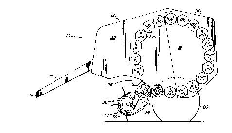
FIG. 1 shows a harvesting machine 10, here shown as a large round baler,
having
a chassis 12, a drawbar 14, a baling chamber 16 and a crop~eed arrangement 18.
The harvesting machine 10 is configured as a large round baler with the baling
chamber 16 being fixed. It would, of course, also be possible to apply the
invention to a
large round baler having a variable baling chamber or to a forage harvester,
combine,
mower or to a baler for making parallelepiped bales. In addition, any such
baler may also
be equipped with a cutter arrangement.
The chassis 12 is supported on the ground by wheels 20 , and is composed of a
3
CA 02199165 2000-OS-16
forward section 22 and a rear flap or discharge gate 24, each including
corresponding side
walls, as is well know and not further described.
A drawbar 14 extends forwardly from the chassis 12 and is used for connecting
the
machine 10 to a towing vehicle, for example, an agricultural tractor, that
tows the harvesting
machine 10 across a field in order to take up crop, such as hay, straw or
grass, deposited
there after being mown.
The baling chamber 16 is representative of a further crop processing
arrangement
and, in the present embodiment, is defined by a plurality of bale-forming
rolls 26, whose
centerlines and, hence, centers of rotation, are generally located on a
circle. The chamber
16 could be variable, in which case it would be defined by belts, chains
and/or movable rolls.
Obviously even in a baler with a fixed baling chamber, belts or chains may be
used instead
of the rolls 26. Some of the rolls 26 are supported for free rotation by
bearings carried by
the forward section 22 of the chassis while the remainder of the rolls 26 are
likewise
rotatably supported by bearings carried by the rear flap or section 24. A roll
26 is omitted
from a lower front region of the baling chamber 16 thus leaving an opening
forming an inlet
28 for receiving crop delivered by the crop feed arrangement 18.
The crop feed arrangement 18 is composed of a conveying surface 30, a
collecting
pick-up 32 and an intermediate conveyor 34, that are combined into a unit and
can be
pivoted vertically as a unit. The crop feed arrangement 18 is wider than the
inlet 28 of the
baling chamber 16. The task of the crop feed arrangement 18 is to take up crop
that has
been mown or threshed out, as the case may be, and left lying on the ground
and to
transport the crop rearwardly across the conveying surface 30 and deliver it
to the baling
chamber inlet 28 while converging the crop stream to the width of the inlet.
The conveying surface 30 consists of a forward conveying section 36, forming a
part
of the pickup 32, and a rear conveying section 38, forming part of the
intermediate conveyor
34, that are so configured and arranged that the crop taken up by the pick-up
32 can slide
on their upper surfaces up to the baling chamber 16.
The forward conveying section 36 is formed by a multitude of sheet metal
strips 42
that are arranged alongside each other and that leave a slot 40 between them.
As can best
be seen in FIG. 3, the strips 42 extend forwardly from a lower rear location
of the pick-up,
then are curved arcuately upwardly at the front of the pick-up and then extend
rearwardly to
an upper rear location adjacent the intermediate conveyor 34.
The rear conveying section 38 consists of a plate 46 provided in its conveying
region
4
CA 02199165 2000-OS-16
s~ .
with slits 44 which are in fore-and-aft alignment with the slots 44 of the
front conveying
section 36.
Although the front and rear conveying sections 36 and 38 are arranged as
separate
parts in the preferred embodiment, they could equally well be manufactured as
a single part.
As can best be seen in FIG. 2, the forward conveying section 36, which appears
at
the bottom of FIG. 2, occupies the width of the pick-up 32 and the rear
conveying section 46
occupies the width of the baling chamber inlet 28.
The pick-up 32 is configured conventionally, with tines 50 thereof being
mounted on
each of several rails 48 arranged transversely to the direction of travel and,
as seen in
FIGS. 1 and 3, being guided for moving clockwise along a curved path 52.
During this
rotary movement, the tines 50 extend through the slots 40 and thereby occupy
various
positions with respect to fhe sheet metal strips 42 with crop being stripped
off the tines 50 at
the region of the strips 42 adjacent the intermediate conveyor 34 thereby
delivering the crop
to the conveyor 34. The design of the pick-up 32 is well known and therefore
does not
require any further detailed description.
The intermediate conveyor 34 can be seen very well in FIG. 2, and consists of
a
center region 54 and two end regions 56. Alternatively, only one end region 56
could be
provided.
A peculiarity of the intermediate conveyor 34 consists of the fact that a
support shaft
58 forming part of the center region 54 also forms part of the respective end
regions 56 and
there includes opposite end portions that are supported in bearings whereby
rotatable
portions of the center and end regions are rotated together. This reduces
drive components
and requires little space for installation.
Another peculiarity can be seen by the fact that the axis of rotation and
therewith the
centerline of the intermediate conveyor 34 extends below an imaginary
transverse plane
extending between the rear end of an upper portion of the conveying section
36, and the
forward end of the rear conveying section 38. Accordingly, the intermediate
conveyor 34
operates as an overshot conveyor where the shaft 58 rotates in the clockwise
direction, as
indicated by the arrow in FIG. 3.
As a further characteristic, the center region 54 is equipped with a multitude
of dogs
60 that are spaced from each other along the shaft 58, with each dog 60
including a pair of
identically configured, diametrically opposite tines 62. The spacing of the
dogs 60
corresponds to the spacing of the slots 40, or the slits 44, and the length or
the spacing of
the shaft 58 to the conveying surface sections 36 and 38 is
selected in such a way that, in their vertical position, the
tines 62 project almost completely beyond the rear conveying
5
CA 02199165 2000-OS-16
section 38. The size of the slits 44 is selected so that only a small gap
remains to the
tines 62 so that the crop can be stripped away cleanly at the entrance to the
baling
chamber 16. In the preferred embodiment, sixteen dogs 60 are provided, but
this is only
given as an example. In any event, the overshot conveying performed by the
dogs 60 is
aggressive while avoiding compression of the crop and possible slugs or
stoppages which
sometimes occurs when crop is compressed.
In the embodiment shown, all tines 62 in the diametrically opposite groups, as
viewed looking axially of the shaft 58, are aligned with one another. But,
according to an
embodiment not shown, the outer dogs 60 may be angularly offset, for example
they may
be arranged so that their tines fall along a helical path, with respect to the
remaining inner
dogs 60 in order to attain a continuous conveying of the crop towards the
center in
contrast to a possible intermittent conveying.
The circumferential speed of the collecting conveyor 32 and of the
intermediate
conveyor 34 is preferably the same, producing synchronous rotation with the
result that the
crop conveyed is transmitted uniformly and is not torn apart.
The outside diameter of the center region 54 and that of the end regions 56
are not
identical, but the difference is so slight that transition problems cannot
develop.
The dogs 60 are attached to the shaft 58 and spaced at a distance from one
another by intervening sleeves 78 of metal or plastic applied to the shaft 58.
The
connection of the dogs 60 to the shaft 58 is performed either with friction
locking or a step.
The end regions 56 are configured as screws conveyors operating as overshot
conveyors which rotate clockwise as seen in FIG. 3, since they are attached to
the same
shaft 58. The configuration is designed so that a screw tube 64 occupies
approximately
two-thirds of the total diameter of the end region 56, while screw helices 66
occupy only
one-third. Therefore and in connection with its overshot conveying, the end
regions 56
operate less as screw conveyors than as deflectors, that divert the crop
towards the
center. Such deflectors are known from the above-identified European Patent
Application
published under No. 0 286 776 A1. The screw helices 66 of each of the end
regions 56
are arranged as opposite hands to each other. FIG. 2 also makes it clear that
the end
regions 56 extend from the outer side of the pick-up 32 up to slightly within
the space
bordered by the side walls of the baling chamber 16.
6
CA 02199165 2000-OS-16
As can best be seen in FIG. 4, a pan 68 is located under and partly surrounds
the
circumference of each end region 56. The purpose of the pan 68 is to avoid the
loss of
valuable forage when broken crop is encountered, for example, very dry hay,
which
otherwise would fall to the ground and be lost there. The forward edge of the
pan 68 ends
at the plane of the forward conveyor section 36. A stripper or deflector 70 is
located above
the pan 68 and extends from above to the screw helices 66 and that possibly;
prevents crop
from being carried along by the end regions 56 that are rotating upward which
could result in
blockages or problems of crop wrapping around rotating parts.
The upper side of the plate 46 of the rear conveying section 38 follows the
inner
ends of the scrapers 70 by an angle greater than 35° and less than
90° about the axis of the
shaft 58. Also, preferably, a given set of tines 62, is positioned in an
angular zone beginning
30° ahead of and ending 30° behind the angular position of the
inner ends of the screw
helices 66, the angular position of the tines 62, projecting forwardly from
the shaft 58 as
viewed in FIG. 4, lagging the inner end of the screw helix 66 by about
45°. In this way, the
lead of the helices 66 of the end regions 56 is not limited too greatly and
the transfer to the
center region 54 occurs without any problems. The magnitude of the individual
angles and
the relationship of the screw tube 64 and the screw helices 66 have the result
that the entire
sideways movement of the crop is accomplished in from one-half to one entire
revolution of
the intermediate conveyor 34.
According to a further development of the crop feed arrangement 18, as shown
associated with the left-hand end region 56, the pans 68 extend further
inward, that is to the
longitudinal center plane of the feed arrangement 18, than do the screw tube
64 and the
screw helices 66 so as to define a free space at the end of each pan 68. The
pans 68 are
formed about the shaft 58 at a radius slightly greater than that of the outer
tips of the tines
62 and the tines of the outer dog 60 of the center region 54 pads through the
pan 68 and
eject broken crop contained therein.
In addition, as shown in FIG. 4, each end region 56 includes a hold down 72
that
consists of a flap 74, which is pivoted vertically from the chassis 12 or
attached to a wall of
the crop feed arrangement 18. The flap 74 is bent near its center and thereby
includes a
level and an inclined section. A weight 76 is welded or otherwise attached to
a forward
edge of the level section, with the rear of the angled section being hinged to
the chassis 12
or the feed arrangement 18 for free vertical pivoting about a horizontal
shaft. In place of the
weight 76, a spring or the like could be provided, in order to bias the flap
74 downward, it
7
CA 02199165 2000-OS-16
being noted that a rear end of the flap is bent to form a stop
for maintaining the flap in a position where the inclined
section extends in general parallel relationship to ari ~zpper
front quadrant of the circumferential surface of each of the
end regions 56 and the level section extends generally
horizontally from a location forwardly of the end
regions. Thus the hold down 72 prevents the crop from being thrown upward and
constantly holds crop in engagement with the screw helixes 66, which leads to
an effective
sideways conveying of the crop towards the center of the feed an-angement 18.
The speed of the pick-up 32, the intermediate conveyor 34 and the baling
chamber
rolls 26 is equal or generally equal, so that even when bale formation is just
beginning at
the inlet opening 28, no -problems in the acceptance-of crop can occur. The
coordination
of speeds and of the distance existing between.the intermediate conveyor 34
and the inlet
opening 28 provides the assurance that the formation of the bale proceeds
without any
problems and that, when net is being used to wrap a finished bale, the net
does not come
into contact with, and hence is not destroyed by, the intermediate conveyor
34.
In contrast to the above embodiments, the center region 54 and the end regions
56
could be driven at differing speeds despite the fact that they are supported
in bearings on
the same shaft 58.
8