Note: Descriptions are shown in the official language in which they were submitted.
WO 96/07484 PG"T/GB95/02108
-1- 0 2 1 ~ 9 4'1 2
EhECTROSTATIC SPRAYING I1EVICE
The present invention relates to an
electrostatic spraying device and, in particular, to
an electrostatic spraying device for dispensing liquid
fragrances such as air fresheners or insecticides, or
for other applications such as aromatherapy, air
purification or for personal care applications, for
example as an inhaler, or an aerosol applicator.
Air freshening devices in whi~~h there is a slow
release of vapour from a container containing a liquid
air freshener are well known in the art.
Electrostatic devices for spraying liquids are
also well known in the art. In such electrostatic
spraying devices a liquid is drawn out preponderantly
by electrostatic forces into ligaments which break up-
into electrically charged droplets.
WO-A-93/06937 discloses an electrostatic
spraying device for spraying liquids comprising a
nozzle in the form of a wick which is contacted with a
reservoir containing the liquid to be sprayed. The
wick is fabricated from a sheet of a resiliently
deformable polymeric foam material of open celled
structure and an edge of the sheet is profiled to form
a plurality of sites at which liquid ligaments can be
produced.
EP-A-0486198 discloses an electrostatic
spraying device incorporating a cartridge containing a
liquid, such as a fragrance producing oil, which is to
be sprayed via a vertically disposed capillary
structure, elec~ric potential being applied to the
liquid so that it is drawn across the end face of the
capillary structure and is sprayed as a plurality of
ligaments which break up into droplets.
We have now developed an electrostatic spraying
device for dispensing liquids such as air fresheners,
WO 96/07484 PCT/GB95/02108
-2- ~ ~ ~~
insecticides, aromatherapy oils or liquids for air
purification in which a particular type of wick is '
used in combination with liquids of defined
characteristics in order to provide a controlled '
atomisation of the liquid from the tip of the wick.
Accordingly, the present invention provides an
electrostatic spraying device which comprises:
(i) a reservoir of an electrostatically
sprayable liquid;
(ii) a capillary structure which comprises a
hollow tube having a convoluted inner surface and
being formed of a polymeric material which is
impermeable to the liquid, the capillary structure at
one end contacting the reservoir of the liquid and at
the other end terminating in an atomisation tip, the
capillary structure being such that when oriented
substantially vertically and with the atomisation tip
uppermost, the capillary action is sufficient to
transport the liquid to the outlet at the uppermost
end of the tube; and
(iii) means for applying high voltage to the
liquid in order to cause the liquid to be projected
from the atomisation tip as one or more ligaments and
thereafter to break up into a plurality of
electrically charged droplets.
The present invention also provides a cartridge
for the storage of a liquid suitable for electrostatic
spraying which comprises a cartridge body containing a
reservoir of a liquid as defined above, a capillary
structure as defined above and means for providing an
electrical connection to a high voltage source. The
means for providing an electrical connection to a high
voltage source may comprise an electrical contact, or
alternatively the cartridge may be at least partly
formed from an electrically conducting or semi-
conducting material.
O 96/07484 PCTIGB95/02108
-3_- o2a~94a2
The electrostatically sprayable liquid which
forms the reservoir preferably has a ~~olume
resistivity of from 2.5 x 10⁶ to 5 x 1.08 ohm cm, more
preferably a volume resistivity of from 2.5 x 10~ to
2.5 x 10⁸ ohm cm: The liquid typically has a
viscosity measured at 20°C of 1 to 20cat (1 to 20 x
10'6 m2/s) , preferably a viscosity of :L to lOcst (1 to
x 10'6 m2/s) , more preferably 1.5 to 4cst (1.5 to 4
x 10'6 mZ/s) and still more preferably 2 to 3cst (2 to~
10 3 x 10'6 m2/s) . The liquid is preferably an
air-freshener which is atomised by the electrostatic
spraying device to fragrance the air in which the
device is positioned, such as a room or corridor.
The electrostatically sprayable liquid is,
however, generally a liquid which has a very low non-
volatile resinous residue such that a volume of the
liquid corresponding at least to the volume of the
reservoir, preferably at least to twice the volume of
the reservoir, can be dispensed without blocking the
tube. Preferably the non-volatile resinous residue
content of the liquid is less than O.lo by weight.
The capillary structure used in the present
invention comprises a hollow tube which preferably has
a smooth outer surface. The hollow tube has a
convoluted inner surface which is formed from a
polymeric material which is impermeable to the liquid.
It will be understood that for a capillary tube to be
considered to be convoluted the ratio of the internal
perimeter of the tube to the cross-sectional area is
greater than 2/r where r is the radius of a circle
having the same cross-sectional area as that of the
convoluted tube in question. Preferably, the internal
perimeter of the tube is equal to or greater than the
external perimeter of the tube. The dimensions of the
tube, the material from which it is fabricated and the
properties of the liquid are so chosen that when the
WO 96/07484 PCT/GB95/02108
:.. . ~ ~._4_ 021g94~1~
capillary structure is substantially vertically
oriented with the atomisation tip uppermost the liquid r
is drawn up the inside of the tube by capillary action
to the atomisation tip. When an electrostatic charge
is applied to the liquid in the reservoir the liquid
at the atomisation tip is drawn.into ligaments and
thereafter broken up into a plurality of electrically
charged droplets.
The convoluted inner surface of the hollow tube
may vary from structures in which simple rounded or
pointed projections are directed into the lumen of the
tube to more complex structures in which the
projections may have interdigitating side branches.
The convoluted inner surface of the tube contributes
to the resistance to distortion of the tube during
use.
A particularly preferred polymeric material
from which the capillary structure may be formed is
polyacetal, for example polyacetal PA-06010
manufactured by Aubex Corporation, Japan. The
polymeric capillary tubes manufactured by Aubex
Corporation are manufactured to a very high tolerance .
of ~ 5%, which is important for maintaining uniform
flow rates from one device to the next. Other
polymeric materials which may also be used are
polyethylene, in particular high density polyethylene,
polypropylene, polyethylene terephthalate, polyamide,
poly(ether ether ketone),poly(ether sulphone) or
poly(ether ketone).
The capillary structure preferably has an outer
diameter in the range of from 0.1 to 1.5 mm, more
preferably 0.4 to 0.8mm, still more preferably about
0.6 mm.
The tip of the capillary structure is
preferably planar and cut to an angle, typically of
about 45°, to the axis of the hollow tube. The liquid
-WO 96/07484 PCT/GB95102108
., _5_ 0299412
to be atomised is brought to the atomisation tip by
passive capillary action. It is then drawn out at the
tip by electrostatic forces into ligaments which break
up into electrostatically charged droplets. In order
for this to happen the electric field strength must be
sufficiently high and in order to reduce the voltage
required to produce a sufficient field strength, it is
known to supply the liquid to a sharp edge, the shape
of which intensifies the electric field and from which
the liquid is sprayed as a cloud of 'very small
(micrometer) sized, charged droplets. The charged
droplets are mutually repellant and have a very large
surface area to volume ratio, thus resulting in rapid
evaporation. The charged droplets seek to discharge
on an earthed/grounded surface but remain suspended in
the air as a cloud for long enough to influence large
air spaces.
It is a particular advantage of the present
invention that the capillary structures with the
convoluted inner surfaces enable relatively low
volumes of electrostatically charged liquids to be
sprayed consistently over long periods of time of up
to four weeks to eight weeks. The capillary structures
with the convulted inner surfaces possess a
significant advantage over capillary tubes with smooth
inner surfaces since they are less sensitive to bubble
entrapment and hence the risk of interrupting
electrical continuity through the liquid column to the
tip. With a plain bore tube, a bubble of air
entrapped, in the tube will be likely to separate the
column of liquid into two parts, whilst with a
convoluted tube it is unlikely, even if a bubble is
entrapped, for the liquid column to be split into two
parts. Thus, electrical continuity is maintained and
the device can continue to spray. 7:n addition, since
the convoluted tube has a greater surface area in
WO 96/07484 PG"T/GB95/02108
-6- 0 2 1 9 9 4 1 ~
contact with the liquid than a plain bore tube, the
capillary force available to force an entrapped bubble
out of the tube is increased.
The means.for applying a high voltage to the
. liquid preferably operates at a potential of from 2 to
25 kV, more preferably at a potential of from 8 to 15
kV and most preferably at a potential of from 10 to 12
kV.
In a preferred aspect of the present invention,
for example when the device is to be used for air
freshening, the means for applying an electrostatic
charge to the liquid may be adapted for intermittent
application. In this manner the electrostatic
spraying device of the present invention may be
operated intermittently, for example using an integral
timer to switch the device into the operating mode
with the application of the electrostatic charge to
the liquid. Conveniently, the device of the present
invention may be. activated at 1 to 15 minute
intervals, preferably 10 to 12 minutes, for a period
of from 0.5 to 5 minutes, preferably 2 to 4 minutes,
. more preferably 3 minutes. In this manner, when the
liquid is a fragrance, the perception of the air
freshening effect achieved by the fragrance is
enhanced. When the device is in its non operational
mode the liquid fills the capillary tube and with the
voltage switched off the meniscus of the liquid is
located at the open end of the tube, but not at the
leading extremity of the tube from which the liquid is
atomised. When the voltage is applied, the liquid is
r
drawn from the column filling the tube across the end
face of the tube and is atomized from the atomisation
tip of the tube. When the voltage is switched off, the
liquid retracts so that the meniscus of liquid is
again located within the tube where it is retained by
surface tension forces. The device of the present
~WO 96/0'7484 PCT/GB95I02108
0299g4~2
invention, when adapted for intermittent use, is
particularly advantageous since the .liquid product and
batteries have an extended life as compared to a
device that continually emanates a fragrance or
insecticide.
The present invention also includes within its
scope an electrostatic spraying device which comprises
a cartridge as hereinbefore defined, a housing into
which the cartridge is adapted to be removably located
with the capillary structure extending substantially
vertically, and a high voltage source located within
the housing for the application of an electrostatic
potential to the electrical connection on the said
cartridge. The high voltage source :may comprise, for
example, high voltage generating circuitry powered by
a low voltage battery. The electrical connection on
the cartridge may comprise an electrical contact
extending through the base of the cartridge or,
alternatively, the cartridge may be at least partly
formed from an electrically conducting or semi-
conducting material.
A particular advantage of the present invention
is that the atomisation tip is arranged to spray
generally vertically upwards without requiring a
positive head. Preferably the cartridge of the
present invention is designed so that there is a
substantially constant head of liquid and the
difference in liquid level between the full and the
nearly empty levels does not significantly affect the
charging of the liquid to the atomisation tip.
One way of achieving a substantially constant
head of liquid is for the cartridge to be of a
generally squat configuration with a vertical
dimension significantly less than its horizontal
dimensions so that it can contact a significant amount
of liquid while producing only a small change in
WO 96/07484 PCTIGB95I02108
_. , _., : ~2a994a2
liquid level between full and nearly empty conditions.
Another way of achieving a constant head is disclosed ,
in WO 95/06521.
For air freshening of a typical room the ,
delivery of 0.3 grams of the liquid fragrance per day
would provide a satisfactory level of fragrance. A
cartridge containing 10 grams of the liquid fragrance
would thus provide air freshening for one month.
The present invention will be further described
with reference to the accompanying drawings, in which:
Figure 1 is a cross section of a capillary
structure for use in accordance with the invention;
Figures 2A to 2H illustrate cross sections of
other capillary structures for use in accordance with
the invention; and
Figure 3 is a schematic view of an
electrostatic spraying device in accordance with the
present invention.
Referring to the drawings, Figure 1 illustrates
in cross section, a capillary structure which is
suitable for use in the present invention. The
capillary structure is shown generally at 1 and is a
cross section of a polyacetal hollow tube sold by
Aubex Corporation of Japan, under the number PA-06010.
The hollow tube, as shown in cross section, has a
smooth outer surface 2 and a convoluted inner surface
3. The tube has an outer diameter of 0.6 mm.
Figures 2A to 2H illustrate the cross sections
of alternative capillary structures which have
convoluted inner surfaces. As can be seen from these
drawings, the convoluted inner surfaces may be of a
relatively simp~e design as shown in Figure 2H, or of
more complex design as shown in the other Figures. "
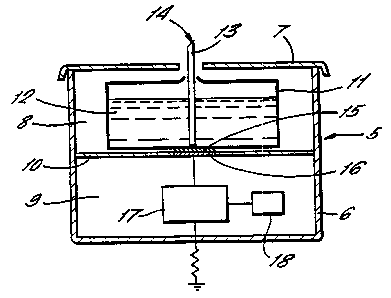
Figure 3 illustrates an electrostatic spraying
device comprising a housing 5, which consists of a
body portion 6 and a removable lid 7. The housing is
WO 96!07484 PCTIGB95/02108
~21~Ig412
-9-
divided into two separate compartments, an upper
compartment 8 and a lower compartment 9, by means of
an internal wall 10. The upper compartment houses a
cartridge 11 which contains a reservoir of an air
freshener liquid 12 therein. A hollow capillary tube
13 of the type as described with reference to Figure 1
is positioned within the liquid reservoir 12. The air
freshener liquid wets the capillary structure 13 by
passive capillary action so that liquid is present at
the atomisation tip 14 of the capillary structure 13.
The base of the cartridge 11 has a connector 15
integrally formed therein. The cart~_-idge rests upon
the inner wall 10 of the housing immEadiately above a
connector 16 which is formed in the :said inner wall.
A high voltage output is supplied from a high voltage
generating circuitry 17, powered by ~3 low voltage
battery (not shown) via connections :L6 and 15 to the
air freshener liquid 12. The circuii~ry 17 is
controlled by means of a timer 18 which is also housed
in the lower portion of the housing.
When the timer is on, the high voltage is
applied to the liquid air freshener :L2 contained in
the cartridge 11 to effect electrostatic spraying of
the liquid from the atomisation tip :L4 of the hollow
~ capillary structure 13. The timer may be, for
example, operated for 3 minutes in every 15 minutes,
i.e 4 times per hour. When the timer is off, the air
freshener liquid will again wet the capillary
structure 13 so that the atomisation tip 14 contains
air freshener liquid ready for electrostatic spraying
when the timer is next in the on modes. It will be
noted that the circuit has a connection to earth via
the bottom wall of the housing body ti.
The cover 7 of the housing is fabricated from
an electrically insulating plastics material such as
polypropylene or polyethylene so thai_ the cover does
WO 96/07484 PCT/GB95/02108
-lo-
0219941
not,immediately cause the electrostatic spray to
earth. Liquid air freshener 12 contained in the
container will meet the requirements of viscosity and
volume resistivity as hereinbefore defined.
Preferably the air freshener liquid will have a very
low non-volatile resinous residue of less than 0.1% by
weight, since otherwise any non-volatile material in
the formulation will accumulate and interfere with the
free-flow of the air freshener liquid, especially at
the atomisation tip. The air freshener liquid should
also be free from any particulate material, since any
particulates would interfere with the free-flow of
liquid within the capillary structure. As previously
described, the air freshener liquid rises to the upper
open end of the capillary structure 13 by passive
capillary action and under the influence of the
applied high voltage (which may be negative or
positive) is projected from the atomisation tip as one
or more ligaments which break up into particles which
repel one another to form a cloud of atomised mist.
The particles are drawn away from the atomisation tip
towards any objects in the vicinity of the device
which are at earth potential.
It will be noted that the cartridge 11,
containing the air freshener liquid is relatively
squat and this enables the air freshener liquid to be
drawn into the capillary structure by passive
capillary action.without the height of the liquid in
the container having much effect on the performance.
When the air freshener cartridge is spent, then the
lid 7 of the housing may be removed and a new
cartridge inserted ready for use.