Language selection

Search

Patent 2199696 Summary

Third-party information liability

Some of the information on this Web page has been provided by external sources. The Government of Canada is not responsible for the accuracy, reliability or currency of the information supplied by external sources. Users wishing to rely upon this information should consult directly with the source of the information. Content provided by external sources is not subject to official languages, privacy and accessibility requirements.

Claims and Abstract availability

Any discrepancies in the text and image of the Claims and Abstract are due to differing posting times. Text of the Claims and Abstract are posted:

  • At the time the application is open to public inspection;
  • At the time of issue of the patent (grant).
(12) Patent Application: (11) CA 2199696
(54) English Title: FOOD BLENDER
(54) French Title: MELANGEUR
Status: Deemed Abandoned and Beyond the Period of Reinstatement - Pending Response to Notice of Disregarded Communication
Bibliographic Data
(51) International Patent Classification (IPC):
  • A47J 44/00 (2006.01)
  • A47J 43/07 (2006.01)
(72) Inventors :
  • BARKER, MARIO JOHN (Australia)
(73) Owners :
  • BREVILLE PTY LTD.
(71) Applicants :
  • BREVILLE PTY LTD. (Australia)
(74) Agent: BKP GP
(74) Associate agent:
(45) Issued:
(22) Filed Date: 1997-03-11
(41) Open to Public Inspection: 1997-09-13
Availability of licence: N/A
Dedicated to the Public: N/A
(25) Language of filing: English

Patent Cooperation Treaty (PCT): No

(30) Application Priority Data:
Application No. Country/Territory Date
PN8643 (Australia) 1996-03-13

Abstracts

English Abstract


A blender comprising a jar or jug having a wall, an inner surface of which
extends substantially vertically except towards the lower end and which has
on the inner surface a plurality of longitudinally extending circumferentially
spaced ribs projecting from the wall towards the central axis of the jar or jug
there being on a central vertical spindle near the bottom of the jar or jug a
first rotating blade assembly having at its lower end a drive connection for
an electric motor, the blade assembly comprising of a pair of blades projecting
radially from the central axis, a second assembly of blades being mounted on
the central spindle at a level higher than that of the first assembly, the
second assembly consisting of a plurality of blades extending radially
outwards from the central axis at about the same level but in different
directions and at different angles to the central axis.


French Abstract

Mélangeur comprenant un bocal ou un pot ayant une paroi, une surface intérieure, essentiellement verticale sauf dans sa partie inférieure, et comportant sur sa surface intérieure plusieurs nervures longitudinales disposées sur sa circonférence faisant saillie en direction de l'axe central du bocal ou du pot, un premier ensemble de coupe rotatif se trouvant sur un arbre central vertical près du fond du bocal ou du pot et comportant dans sa partie inférieure un élément de connexion à un moteur électrique, le premier ensemble de coupe comportant deux lames faisant saillie radialement à partir de l'axe central, un deuxième ensemble de coupe étant monté sur l'arbre central au-dessus du premier ensemble, le deuxième ensemble de coupe comportant plusieurs lames faisant saillie radialement à partir de l'axe central, environ à la même hauteur mais dans des directions différentes et à des angles différents par rapport à l'axe central.

Claims

Note: Claims are shown in the official language in which they were submitted.

1. A blender comprising a jar or jug having a wall an inner surface of
which extends substantially vertically except towards the lower end and
which has on the inner surface a plurality of longitudinally extending
circumferentially spaced ribs projecting from the wall towards a central axis
of the jug or jar, there being on a central vertical spindle near the bottom of
the jar or jug a first rotating blade assembly having at its lower and means
for engaging a driving motor, the blade assembly consisting of a pair of
blades projecting radially from the central axis at about the same level, one
of said blades projecting horizontally and the other being directed
downwardly at an angle, the outer end of the horizontally directed blade
during, rotation of the assembly, passing close to the inwardly projecting
ribs, a second assembly of blades being mounted on the central vertical
spindle at a level higher than that of the first assembly, the second assembly
consisting of a plurality of blades extending radially outwards from the
central axis at about the same level but in different directions and at
different angles to the central axis.
2. A blender as claimed in claim 1 wherein a conical structure is provided
in the bottom of the jug to provide a space such that food or ice will be
circulated rather than stay under the first rotating blade assembly, an upper
surface of the conical structure making the same angle with the central axis
as does the downwardly directed blade of the first rotating blade assembly
3. A blender as claimed in claim e wherein the upper surface of the
conical structure and the downwardly directed blade make all angle of about
55° with the central axis.
4. A blender as claimed in claim 1 wherein the second assembly of blades
consists of four blades spaced uniformly around the central axis and
extending radially outwardly therefrom and being arranged at approximately
25 35, 15 and 75 degrees respectively to the central axis, the second
assembly of blades being arranged near the middle of the jar or jug

Description

Note: Descriptions are shown in the official language in which they were submitted.


2199696
Tl~e present illvention relates to a food blender of a kind col-s~sting
of a ja~ or jug us~ally of glass wit~lin u~hich is moullted a tOtating blade or
blades a- the botto~ll of the jar or ju~s. The food to be proc~ssed which may
consist of portions of fi't1it or vegetables or even ice is placed in the ~ar or jug
s and the blades rotated r~pldly to convert the food Irlto a slurry or crush theice flllely,
Knowll food ble~lders h~ve a llumber of shorlcomi~lgs of which tbe
followill~ are si~llifical~t
a) when focd is of a thick col~sistonc~ al~d ill a lArge volume it is
unable to circulate within the blellder ju8
b) food and ice tend to make an arch alound tlle blades which
lesults ill tile blade~ not havil-g colltact with the food or ice and
therefor~ tt is noL p~ocessed and;
c) the cerLter of the blad0s do l~ot cu~ and as the vorte7t formed by
rotation of the blades takes the Eood to the cellter of the blades
the result is tllat large pieces food alld ice are not proccgsed,
Tlle object of the pr2gent invelltion is to ovelcome tllese
shortcolllings aud to provide a blender tllat ~ill operate more effecti~ely.
A blender according to the i1lve~ltio~l complises a jar or ju~ havillg a
20 wall, ar~ ller surtace of vvhich extends substantiall~ vertically except
towards the ~ower end a~ld v~llich has oll the iu~ler sul~face a pluralit~ of
lo~lgitudillally extendin6 ~ u~r~ litdly spaced ribs projec~lng from the
wal~ towards a centlal axis of the j~lg or jar, there bei~lg on a centl~al vertical
spindle near the bottorrl of the jar or jug a first rotatir~ blade assembly
2s IIAving at its ~ower elld meAILS for erleagillg a driving Illotor. the blade
assembly consiscing of a pair of blades plojecting radially fronl the celltral
AXis at about the same level. one of said blades projecting horizontally al~d
the otl~er bein8 directed dowllwerdly at an angle. the out~r end of tlle
horizoLltally directed blade durillg, rotatioll of the asset~lbly. passing clos~ to
30 the illv.~al~dly ploject~llg ribs, a second assembly of blades bein" Illounted on
the celltlal vertical spit~dle at a level higher tha~l that of the first ass~mbly.
the socond asselllbly consisti~g of a plurality of blates extending ladially
outv.~ards from the celltral axis at ~bou~ the salue level but in diff~:retlt
directoolLs al~d at diff2rent angles to th~ celltral axis.

2lg9696
ILI orde~ that the ~lature of the invention rnay be better uDderstoo~
and put i~ltO practice a prefened form thereof is hereinafter desclibed, by
~va~ of examp~e, with ~eference to th~ ~,,col..,var~ drav~ s in which:-
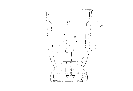
Figure 1 is a plan ~~iew of the blender,
Fig-lse 2 is a vertical section orl line A~ of Fig~lre 1 and;
Fig~ue 3 is a vertic~l section oll line H-H of ~igure 1.
The bleDder in iLs preferred forrn consists oE a j~lg, made pleferably
of gless, ha~ a llandle 11. The inner vvall 1Z of the i-l8 is more or less
vertical in its upper part cun~ing in towards ~ts lov.er elld.
Within the juB 12 Oil its vertical axis i9 a spilldle 13 carried ill a
bearin~ 14 and havillg at iLs lower elld a dlive ellsaR~Ilg Illeans 15 whereby it
may be co~ ected to an electric driving ~lotor alTanged ill a base oll which
tlle j~lg is norlually placed. The spindle 13 c~rries on it two assemblius of
blades, a lower assembly conSisti~l~ of blades D and C and an upper
assembly Co~lsiStil~g of blades D, E, F, and G. Tlle bea~ g 14 is calried by d
collical structu~e 16 which not o~ supports the beal~ 14 but wllicl~
sllapes the bottom of the jug in the mamler described below.
The blade B of the lo~er asselllbly projects horizontally and passes
very close to the ribs 1; formed oll the irmer wall of Llle jllg 10. The other of
zo tlle lower blad~s C is til~ected downwardl~ at an a~gle of ss degrees from tlle
axis aho-lt wllich it rotates auld lies generally palallel to tbe surface Or theconical sttuct~lre 16.
The upper asselubly of blades D, E. ~ aDd G i5 arranged near the
l~liddle of the j~g as show~ the drawillgs fl~ol~ which it will be see~l tha
the blades ale of different lellgths a~ld arranged ~t difrerent arlgles which iuprefell~ed pn~hr~ t are al approximately ~5, 35, 15, 75 degrees to the axis.
The blades are so alrallged so that there is a blade ~t each of a n~ln~ber of
ài~rerent augles to prevQrlt there being a~ly norl-CUttiUg point at wllich rood
ant ice calmot be processed. The fact that this assembly of blades is
s~ n-tt; Illy lligher in the ju~ than the lower set ca-lses the blending actio
of the blellder to t~ke placs in the center of f~od or ice placed ill it ratllerthan the bottom. Tlle lo~r assembly o~ blades does the final choppln~ alld
by re~soll of tl~e ract tllat the blades a~e short enou~h to miss tlle rib~ 17
durin~ rota~ior,, pr~vent food and ice forraing an arcll as llorraal ~lenders doby CUttillg the walls of the arch alld collapsing them therefore processin~
food tllorou~hly.

219969G
The ~l.9n. ~ nt of ribs is to cleate an upward lift ~hich forms a
voltex back tllrough the ceDtre. Food and ice passillg the lower ~lades tend
to be crushed between ~l1em alld tlle ribs.
It is import~Dt tl~at there is ~ of syace at tl~e lowet end of tlle blellder
S iuu such tllat food cal~ circulate al~d be folced up tlle side of the jugs wall.
The jug irl the pleferred fornl has an almost vèrticAI side ~Ya~l to ~ive as
tlluch lirt as posslble. rhis is in contlast ~sritl1 the ~ iul~al blelld~r th~t
has a cone sh~ped jug in ~-~licll the food go2s thro~lgh the centel of tite jug
alld can~lot return back up the sides because the food will have to pass
10 almvst back up tlte center to reach the top to co~nplete its journey so that a
negative and equal reactioll neuhalises a~ movemellt.
The collical stl~cture 1~ provides A shape for t~le l~ottom of the ju~
tlle space ill which is lilllited so tl~at food or ice ~'~ill be ci~cula~ed ratl~er
thall sta~ under the lower blades.
Optimum ~ r.a.. ld"c~ of the blellder is obtained u~hell the speed is
corlect. The bleilder may be operated pleferAbly at a low speed of 1~30 rprn
Ol a lligh speed of 2000rpm
As all adjustment to ~.l1e lsle~,der thel e may be plovided all a~tom3tic
ice crushillg .~ &c~ l that collSists of an auto plllse switch which
20 sUitC~12S on alld off aulomatically. Th~ motor drivill~, the spindle 13 is
switched on for 0.5 of a secon~1 which causes sll1all portiorls oI ice to be
clushed alld throwll to the top of the ju~,. To allo~h the ice to s2ttle at the
bottoll~ of the jug and co~er ~he blades n1otor is switched off for five secoDdsduring v.~llich tilne the motor coll~es to a complet2 stop allowill~ t~le ~IIICUt
zs ice to rest around th2 blades
It ~ill be d~.e~.i;dtl~ by persolls skilled in the aut that llurlerous
~ ariations andfor ~ i fi~ti~ may be made to ~lle invention as sho~Nn in
the ~pecific ~ J~ ithout departing frorrl the spirit or scope of the
illverltion as broadly described. The prese~1t l~ o~ n~nt5 al~e the~efore lo
30 b2 collsiùered in all respects as illustrative and not restltctiYe.

Representative Drawing
A single figure which represents the drawing illustrating the invention.
Administrative Status

2024-08-01:As part of the Next Generation Patents (NGP) transition, the Canadian Patents Database (CPD) now contains a more detailed Event History, which replicates the Event Log of our new back-office solution.

Please note that "Inactive:" events refers to events no longer in use in our new back-office solution.

For a clearer understanding of the status of the application/patent presented on this page, the site Disclaimer , as well as the definitions for Patent , Event History , Maintenance Fee  and Payment History  should be consulted.

Event History

Description Date
Inactive: IPC from MCD 2006-03-12
Application Not Reinstated by Deadline 2002-03-11
Time Limit for Reversal Expired 2002-03-11
Deemed Abandoned - Failure to Respond to Maintenance Fee Notice 2001-03-12
Letter Sent 1998-02-23
Filing Requirements Determined Compliant 1997-10-31
Inactive: Filing certificate - No RFE (English) 1997-10-31
Application Published (Open to Public Inspection) 1997-09-13
Inactive: Single transfer 1997-09-12
Inactive: First IPC assigned 1997-08-06
Inactive: IPC assigned 1997-08-06
Amendment Received - Voluntary Amendment 1997-05-14

Abandonment History

Abandonment Date Reason Reinstatement Date
2001-03-12

Maintenance Fee

The last payment was received on 2000-02-16

Note : If the full payment has not been received on or before the date indicated, a further fee may be required which may be one of the following

  • the reinstatement fee;
  • the late payment fee; or
  • additional fee to reverse deemed expiry.

Please refer to the CIPO Patent Fees web page to see all current fee amounts.

Fee History

Fee Type Anniversary Year Due Date Paid Date
Application fee - standard 1997-03-11
Registration of a document 1997-09-12
MF (application, 2nd anniv.) - standard 02 1999-03-11 1999-02-16
MF (application, 3rd anniv.) - standard 03 2000-03-13 2000-02-16
Owners on Record

Note: Records showing the ownership history in alphabetical order.

Current Owners on Record
BREVILLE PTY LTD.
Past Owners on Record
MARIO JOHN BARKER
Past Owners that do not appear in the "Owners on Record" listing will appear in other documentation within the application.
Documents

To view selected files, please enter reCAPTCHA code :


To view images, click a link in the Document Description column. To download the documents, select one or more checkboxes in the first column and then click the "Download Selected in PDF format (Zip Archive)" or the "Download Selected as Single PDF" button.

List of published and non-published patent-specific documents on the CPD .

If you have any difficulty accessing content, you can call the Client Service Centre at 1-866-997-1936 or send them an e-mail at CIPO Client Service Centre.


Document
Description 
Date
(yyyy-mm-dd) 
Number of pages   Size of Image (KB) 
Description 1997-05-14 3 152
Abstract 1997-05-14 1 21
Drawings 1997-05-14 3 55
Claims 1997-05-14 1 48
Cover Page 1997-10-24 1 54
Abstract 1997-03-11 1 20
Description 1997-03-11 3 138
Drawings 1997-03-11 3 59
Claims 1997-03-11 1 44
Representative drawing 1997-10-24 1 10
Filing Certificate (English) 1997-10-31 1 164
Courtesy - Certificate of registration (related document(s)) 1998-02-23 1 118
Reminder of maintenance fee due 1998-11-16 1 110
Courtesy - Abandonment Letter (Maintenance Fee) 2001-04-09 1 182
Reminder - Request for Examination 2001-11-14 1 118
Correspondence 1997-04-08 1 28
Fees 1999-02-16 1 38
Fees 2000-02-16 1 39