Language selection

Search

Patent 2199966 Summary

Third-party information liability

Some of the information on this Web page has been provided by external sources. The Government of Canada is not responsible for the accuracy, reliability or currency of the information supplied by external sources. Users wishing to rely upon this information should consult directly with the source of the information. Content provided by external sources is not subject to official languages, privacy and accessibility requirements.

Claims and Abstract availability

Any discrepancies in the text and image of the Claims and Abstract are due to differing posting times. Text of the Claims and Abstract are posted:

  • At the time the application is open to public inspection;
  • At the time of issue of the patent (grant).
(12) Patent: (11) CA 2199966
(54) English Title: ARRANGEMENT FOR FIXING AN ELEVATOR ROPE
(54) French Title: DISPOSITIF DE FIXATION D'UN CABLE D'ASCENSEUR
Status: Term Expired - Post Grant Beyond Limit
Bibliographic Data
(51) International Patent Classification (IPC):
  • B66B 7/06 (2006.01)
  • B66B 7/02 (2006.01)
  • B66B 7/08 (2006.01)
  • B66B 11/00 (2006.01)
  • B66B 11/04 (2006.01)
(72) Inventors :
  • MUSTALAHTI, JORMA (Finland)
  • AULANKO, ESKO (Finland)
  • HAKALA, HARRI (Finland)
(73) Owners :
  • KONE OY
(71) Applicants :
  • KONE OY (Finland)
(74) Agent: G. RONALD BELL & ASSOCIATES
(74) Associate agent:
(45) Issued: 2000-05-23
(86) PCT Filing Date: 1995-09-27
(87) Open to Public Inspection: 1996-04-04
Examination requested: 1997-07-17
Availability of licence: N/A
Dedicated to the Public: N/A
(25) Language of filing: English

Patent Cooperation Treaty (PCT): Yes
(86) PCT Filing Number: PCT/FI1995/000530
(87) International Publication Number: WO 1996009978
(85) National Entry: 1997-03-13

(30) Application Priority Data:
Application No. Country/Territory Date
944475 (Finland) 1994-09-27

Abstracts

English Abstract


According to the invention, at least one end of the elevator ropes (8) is
fixed to a guide rail (4, 7) of the elevator. According to an embodiment of
the invention, the whole elevator is so suspended by its ropes (8) that all
vertical forces are transmitted by the guide rails (4...7) to the bottom (27)
of the shaft (1). The invention provides the advantages that the elevator is
easy to install and that the vertical forces are transmitted by the guide
rails (4...7) to the bottom (27) of the shaft (1), permitting a lighter
construction of shaft walls.


French Abstract

Selon l'invention une extrémité au moins du câble (8) de l'ascenseur est fixée aux rails (4, 7) de guidage de l'ascenseur. Dans l'une des variantes de l'invention, l'ensemble de l'ascenseur est suspendu par ses câbles (8) de manière telle que toutes les forces verticales soient transmises par les rails de guidage (4...7) à la base (27) de la cage (1). L'invention présente des avantages en matière de simplicité d'installation et de transmission des forces verticales par les rails de guidage (4...7) à la base (27) de la cage (1), ce qui permet une construction plus légère des parois de la cage.

Claims

Note: Claims are shown in the official language in which they were submitted.

CLAIMS
1. Arrangement for fixing the elevator rope (8) in an
elevator (29) comprising an elevator car (2), an elevator
counterweight (3), elevator guide rails (4,5),
counterweight guide rails (6,7), an elevator machinery
(14), an elevator rope (8) having two ends at least one of
which is fixed to one of the guide rails (4,5,6,7) of the
elevator or counterweight, and at least one diverting
pulley (11,12,13), by means of which the elevator car (2)
is moved vertically in an elevator shaft (1),
characterized in that the elevator rope (8) fixed to a
guide rail (4) is driven by the elevator machinery (14)
which is also mounted on one of the guide rails (5).
2. Arrangement for using a guide rail (4,5,6,7) as a
supporting element of an elevator (29) comprising an
elevator car (2), an elevator counterweight (3), elevator
guide rails (4,5), counterweight guide rails (6,7), an
elevator machinery (14), an elevator rope (8) and at least
one diverting pulley (11,12,13), by means of which the
elevator car (2) is moved vertically in an elevator shaft
(1), and auxiliary equipment (30,33) of the elevator (2),
characterized in that the elevator (2) together with its
equipment is suspended on the guide rails (4,5,6,7) by
fixing both ends of the elevator rope (8), the elevator
machinery (14) and the auxliary equipment (30,33) of the
elevator each to one of the guide rails (4,5,6,7) of the
elevator (29) or counterweight (3).

Description

Note: Descriptions are shown in the official language in which they were submitted.


9 6 ~
WO !>li~-~g~ /~ PCT/1~195/00530
ARRANGE~IENT FOR FIXING AN ELEVATOR ROPE
t 5 The present invention relates to an arrangement as defined
in the preamble of claim l for fixing the elevator rope in
an elevator and to an arrangement as defined in the
preamble of claim 6 for the use of guide rails as
supporting elements of an elevator and its equipment.
In traction sheave elevators, the ends of the elevator
ropes are conventionally fixed to the elevator shaft or to
anchorages in a machine room in the upper part of the
elevator shaft. The other ends of the elevator ropes are
15 usally fixed by means of springing elements. Similarly,
the diverting pulleys of an elevator are typically mounted
in the elevator shaft or in the machine room, but
diverting pulleys mounted on an elevator guide rail are
also known.
Previously known solutions for the fixing of elevator
ropes have the drawback that the elevator ropes require a
strong anchorage in the building and that the position of
the anchorage in relation to the building, elevator,
25 elevator shaft, elevator machinery and diverting pulleys
must be closely defined. Therefore, fixing the elevator
ropes by known techn;ques requires a long installation
time because a holding element for a rope fixing element
has to be installed first in the elevator shaft or machine
30 room.
The object of the present invention is to produce a new
arrangement for the fixing of elevator ropes, designed to
facilitate the installation of elevator ropes and to
35 reduce the installation time. Another object of the
invention is to eliminate the need for mounting bases for
elevator rope fixing elements mounted in the elevator
shaft or in the machine room. A further object of the

21 ~ 9 9 ~ ~ ~t ' ;1l
WO9G~37X pcTl~5~ r~n ~
invention is to avoid the transmission of vertical forces
of the elevator ropes to the building or to the shaft
walls.
5 To achieve the aims specified above, the arrangement of
the invention for fixing an elevator rope is characterized
by what is said in the characterization part of claim 1
and the arrangement for the use of guide rails as
supporting elements of an elevator and its equipment is
10 characterized by what is said in the characterization part
of claim 3. Other features of the invention are presented
in claim 2.
The invention has the advantage that the installation time
15 and the total installation costs of the elevator are
reduced. To achieve these advantages, the elevator guide
rails are first fixed to the walls of the elevator shaft
in a manner known in itself, e.g. to C-profile beams. Each
end of the elevator rope is fixed to one of the guide
20 rails. The guide rail ends can be provided with holes for
the mounting of rope fixtures at the factory. The elevator
machinery is mounted on one guide rail, and likewise a
diverting pulley, so that all vertical forces of the
elevator are transmitted via the guide rails to the bottom
25 of the shaft. Therefore, the vertical forces impose no
strain on the walls of the building. Thus, the exact
position of the elevator is determined by the guide rails
and the elevator imposes no vertical pressure on the
building. As the elevator ropes are fixed to a guide rail,
30 it follows that no mounting bases for rope fixing elements
need to be installed, thus shortening the installation
time.
The weight of elevator ropes fixed to a guide rail, that
35 of the elevator car and counterweight supported by the
ropes as well as the weight of an elevator machinery
supported by a guide rail, in other words, almost all of
the weight of the whole hoisting function is transmitted

219~96~
wos~/~3s~8 PCT ~ 5/OOS30
by the guide rails to the bottom of the elevator shaft.
The transmission of internal forces of the hoisting
function through the shaft bottom or walls is avoided. An
example of a disadvantageous solution avoided by the
5 invention is an elevator in which the elevator ropes apply
an upward pull to an elevator machinery mounted on the
shaft bottom and to the shaft bottom itself. The invention
also obviates the labor and costs resulting from anchoring
the machinery in the building.
In the following, an embodiment of the invention is
described by the aid of drawings, in which
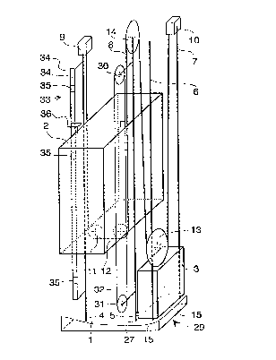
Fig. l presents a diagrammatic view of an elevator
with ropes mounted according to the
invention,
Fig. 2 presents a rope fixing element in
cross-section, and
Fig. 3 presents a rope fixing element in top view.
In Fig. l, the elevator car 2 of an elevator 29 moves
vertically along a first elevator guide rail 4 and a
25 second elevator guide rail 5 mounted in an elevator shaft
l. The counterweight 3 also moves vertically along a first
counterweight guide rail 6 and a second counterweight
guide rail 7 mounted in the shaft. For the sake of
readability of the illustration, the walls of the elevator
30 shaft are not shown except for the bottom parts of two
walls 15. The elevator 2 and the counterweight 3 are
supported and moved by means of an elevator rope 8. The
elevator rope 8 has two ends and consists of a number of
parallel ropes (Fig. 3). The elevator machinery 14 is
35mounted on the top end of one 5 of the guide rails. The
motor of the elevator machinery is a disc-type motor and
the machinery is provided with a traction sheave. The
elevator machinery is not described here in detail because

' r~
WO !~~/J5~7~f 21 9 9 g fi ~ PCT~95/00530 ~
it is outside the scope of this invention. One of the two
ends of the elevator rope is fixed to the top end of the
first elevator guide rail 4 by means of a rope fixing
element 9, from where the elevator rope is passed to the
5 traction sheave of the elevator machinery 14 mounted on
the top end of the second elevator guide rail 5. From
here, the elevator rope is passed to the diverting pulley
13 of the counterweight 3 and then up to a second rope
fixing element 10 mounted on the top end of the second
10 counterweight guide rail 7, by means of which element 10
the other end of the elevator rope is fixed to the guide
rail 7. This second rope fixing element 10 may be
identical with the first rope fixing element 9 illustrated
by Fig. 2, but it can also be implemented without using
15 springing elements to fix the elevator ropes.
As the ropes and machinery of the elevator are mounted on
the guide rails as described above, the vertical forces of
the elevator are transmitted by the guide rails to the
bottom 27 of the shaft 1.
Mounted on the guide rails are also known auxiliary pieces
of eqipment, such as an overspeed governor 30, which is
fixed to guide rail 5, and a device 33 for determining the
elevator position, fixed to guide rail 4. The overspeed
25 governor 30 comprises a closed rope loop 32, one end of
which is passed around a diverting pulley 31 mounted it
the lower part of guide rail 5. As is known, the overspeed
governor causes the elevator to stop e.g. by means of a
safety gear. The position indicating device 33 of the
30 elevator comprises two thin ropes 34 fixed by their top
and bottom ends to guide rail 4 by means of brackets.
Fixed between the ropes 34 are metal plates 35 that
indicate the elevator position as a sensing element 36
moving with the elevator 29 passes them.
Fig. 1 illustrates only one possible arrangement for
fixing the elevator rope according to the invention. The
elevator rope fixing arrangement of the invention can also
~ =

219996~
W096/09978 ' ; PCT/~5J~ o
~ .' '' r~
t .. ~ ,
be implemented by fixing the elevator rope to one of the
guide rails and the elevator machinery to the lower end of
the other one.
5 Fig. 2 shows an elevator rope fixing element 9 sectioned
in a vertical direction. The fixing element has a shape
resembling a box with its front and top sides open. The
frame of the fixing element consists of a bottom plate 20,
a back plate 21 and two side plates 28 joined together.
10 The bottom plate 20 is provided with a number of holes 26
corresponding to the number of elevator ropes, with a rope
supporting element 22 passed through each hole. The rope
supporting element 22 consists of a boltlike body 24 with
a nut 23 and washer on its upper end. Between the washer
15 and plate 20 is a springing element, preferably a helical
spring 25. The lower end of the supporting element is
provided with a conical hole in which a loop of the
elevator rope 8 is formed, and the elevator rope is
anchored in the conical hole by this loop by means of an
20 expander bolt. Thus, each elevator rope is supported on
the bottom plate 20 by a spring. Fixed with screws 19 to
the back plate 21 are two mounting flanges 18, by which
the whole fixing element 9 is attached to the guide rail
4 by means of other screws 17.
Fig. 3 presents the fixing element as seen from above. The
guide rail 4 is fixed to the wall 15 of the elevator shaft
by means of rail clips 16. The rail clips 16 permit
vertical rail movement. Line A-A represents the section
30 shown in Fig. 2.
It is obvious to a person skilled in the art that the
embodiments of the invention are not restricted to the
applications described, but that they may instead be
35 varied in the scope of the following claims.

Representative Drawing
A single figure which represents the drawing illustrating the invention.
Administrative Status

2024-08-01:As part of the Next Generation Patents (NGP) transition, the Canadian Patents Database (CPD) now contains a more detailed Event History, which replicates the Event Log of our new back-office solution.

Please note that "Inactive:" events refers to events no longer in use in our new back-office solution.

For a clearer understanding of the status of the application/patent presented on this page, the site Disclaimer , as well as the definitions for Patent , Event History , Maintenance Fee  and Payment History  should be consulted.

Event History

Description Date
Inactive: Expired (new Act pat) 2015-09-27
Inactive: IPC from MCD 2006-03-12
Grant by Issuance 2000-05-23
Inactive: Cover page published 2000-05-22
Pre-grant 2000-02-22
Inactive: Final fee received 2000-02-22
Notice of Allowance is Issued 1999-09-01
Letter Sent 1999-09-01
Notice of Allowance is Issued 1999-09-01
Inactive: Approved for allowance (AFA) 1999-07-22
Letter Sent 1997-11-06
Letter Sent 1997-10-14
Inactive: IPC assigned 1997-08-12
Inactive: First IPC assigned 1997-08-12
Request for Examination Received 1997-07-17
Request for Examination Requirements Determined Compliant 1997-07-17
All Requirements for Examination Determined Compliant 1997-07-17
Inactive: Single transfer 1997-05-05
Inactive: Courtesy letter - Evidence 1997-04-08
Application Published (Open to Public Inspection) 1996-04-04

Abandonment History

There is no abandonment history.

Maintenance Fee

The last payment was received on 1999-09-20

Note : If the full payment has not been received on or before the date indicated, a further fee may be required which may be one of the following

  • the reinstatement fee;
  • the late payment fee; or
  • additional fee to reverse deemed expiry.

Please refer to the CIPO Patent Fees web page to see all current fee amounts.

Owners on Record

Note: Records showing the ownership history in alphabetical order.

Current Owners on Record
KONE OY
Past Owners on Record
ESKO AULANKO
HARRI HAKALA
JORMA MUSTALAHTI
Past Owners that do not appear in the "Owners on Record" listing will appear in other documentation within the application.
Documents

To view selected files, please enter reCAPTCHA code :


To view images, click a link in the Document Description column. To download the documents, select one or more checkboxes in the first column and then click the "Download Selected in PDF format (Zip Archive)" or the "Download Selected as Single PDF" button.

List of published and non-published patent-specific documents on the CPD .

If you have any difficulty accessing content, you can call the Client Service Centre at 1-866-997-1936 or send them an e-mail at CIPO Client Service Centre.


Document
Description 
Date
(yyyy-mm-dd) 
Number of pages   Size of Image (KB) 
Cover Page 1997-09-11 1 34
Cover Page 2000-04-25 2 54
Abstract 1997-03-13 1 55
Description 1997-03-13 5 238
Claims 1997-03-13 1 39
Drawings 1997-03-13 2 46
Representative drawing 2000-04-25 1 11
Reminder of maintenance fee due 1997-07-24 1 111
Acknowledgement of Request for Examination 1997-11-06 1 178
Courtesy - Certificate of registration (related document(s)) 1997-10-14 1 116
Commissioner's Notice - Application Found Allowable 1999-09-01 1 163
PCT 1997-03-13 7 259
Correspondence 1997-04-08 1 38
Correspondence 2000-02-22 1 30
Fees 1998-09-18 1 44
Fees 1997-09-19 1 49
Fees 1999-09-20 1 45
Fees 2000-07-07 1 47