Note: Descriptions are shown in the official language in which they were submitted.
0 2 2 0 0 û 0 5
.
PROTECTIVE SEIIELD FOR CONTA~ER
FIELD OF TlEIE INVENTION
The present invention relates to a container, more specifically to freight container, and rnore
10 specifically to one or more protective shields applied to the container doors to prevent mechanical
damage during transport.
BACKGROUND OF TEIE INVENTION
Con~ainers, such as freight containers are widely used for shipping goods by road, rail, air and sea.
These structures are typically large rectangular structures specially designed to be handled and
stored in the holds of ships, and on railway flat cars, etc.
2 o These cargo containers are typically closeable by pivoted doors, said doors being held in a closed
position by lockrods extending vertically over the doors and into cooperating receptors fixed on
the surrounding door frame. Said pivoted doors are capable of pivoting due to a hinging means,
typically standard hinges. Moreover, lock arms are attached to such lockrods to pivot them about
their longitudinal axis for release from the receptors, whereby the pivoted doors may be opened.
2 5 To provide a satisfactory weatherproof seal, a rubber strip is often attached around the edges of
the doors. This standard container, locking mechanism, and seal are well known to those skilled
in the art.
Unfortunately the lock rods and hinges for said pivoting doors, and the weatherproof seals are
3 o particularly prone to becoming damaged during transit. It is not uncommon for both the locking
mech~ni~m~ and/or the hinges to become so badly damaged during transit that the doors cannot
be opened when the container reaches its destination. Similarly, if the seals are damaged, the load
can become, among others things, darnp during transport spoiling the contents of the container.
O Z 2 0 0 0 0 5
.
5 Such a delay in being able to open these freight containers can be extremely costly for a number of
reasons. For example, numerous person hours can be lost while thermal cutting equipment is
located and used to open the container. In the case of perishable items, such as foodstuffs, often
the load spoils in the period before the container can be opened. Also the entire locking
mech~ni.cm and/or hinges and/or seals must be replaced before the shipping container can be
1 o reused.
By way of example, freight containers known in the shipping industry as 'mini-containers' are
widely used to transport supplies onto offshore oil-rigs from a helicopter. Weather conditions can
be extreme, causing said mini-container to collide with the rig. The resultant impact(s) frequently
5 render the container impossible to open. Hence, there is an urgent need to protect the locking
mech~nisms and moisture seals on the mini-containers used to transport supplies to offshore oil
rlgs.
Accordingly, there is a need for a simple and inexpensive means of protecting the locking rod
2 o mech~ni.~m~ hinges, and weatherproof seals on freight containers. The invention described herein
is sufficiently adaptable to be able to answer this urgent need for a wide variety of prior art
container door constructions.
SUl~IMARY OF T~E INVENTION
The present invention provides reinforced protective shields to cover the locking rod mechanism
and mounting brackets, hinges, and the rubber seals on container doors thereby preventing
mechanical damage during shipping. A major advantage of the present invention is that it is
possible to weld these protective shields onto existing container doors rather than replacing the
3 o entire door, hinge, seal, or locking mech~ni~m
The objects and advantages of the protective shields, or plates, described in this patent include,
but are not limited to the following: (a) to provide a means of protecting specific areas of freight
0~00 ~05
.
5 containers, which are particularly prone to mechanical darnage during shipping; (b) to provide a
means of protecting the locking rods on freight containers from mechanical damage; (c) to
provide a means of protecting the locking rod mounting brackets on container doors from
meclhanical damage; (d) to provide a means of protecting the moisture seals around the edges of
container doors from mechanical damage; and (e) to provide a means of protecting the hinges on
10 freight containers from mechanical damage.
All of the above advantages can be achieved without adding significant time, costs, or weight to
the c,ontainer, thereby making the present invention clearly advantageous.
15 A further objects of the present invention is to provide an inexpensive means of applying
protective shields to the least robust areas of shipping containers. Hence, the invention can be
attached, for example, by way of being welded, onto existing container doors rather than
replacing the entire door. However, any means of attaching said shields are envisioned by the
present invention.
Yet a further advantage of the present invention is that the sizes of the shields can be adapted to
fit any and all sizes of freight container doors, from the 'mini-containers' up to and including the
48' shipping containers.
2 5 An additional advantage of the present invention is that the shields can be fabricated from
cornmercially available products, thereby providing an economical solution to the problem as
described. It can be seen that the protective shields are compact in design, and do not extend
beyond the other door fittings. This is an important feature so that the freight containers can be
stored in close proximity to other containers in the hold of a ship or the like, providing yet a
3 o further advantage of the invention.
Further objects and advantages of the invention will become apparent from the consideration of
the drawings and the ensuing description.
~ 0 2 2 0 0 0 0 5
BRIEF DESCRIPTION OF T~IE DR~WINGS
The foregoing, as well as other objects and advantages of the invention, will be apparent from the
following detailed description when considered in conjunction with the accompanying drawings,
wherein like reference characters design~te like parts throughout the several views, and wherein:
Figure 1 (PA303A) illustrates the general arrangement. This figure includes front, side and
rear elevation views of the doors, which are fitted with seals.
Figure 2 (PA303B) illustrates the general arrangement. This figure shows the floor plan,
the inverted floor plan and the front elevation.
Figure 3 (PA303C) illustrates the general arrangement. This figure in~ des the inverted
roof plan and includes lifting lug detail.
2 o Figure 4 (PS2 l l) illustrates the door subassembly. This figure shows the rear doors when
closed and viewed from outside with protective shields.
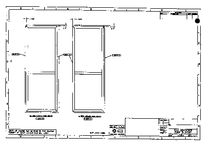
Figure 5 (LS21 l) illustrates the door panel subassembly. This figure shows both the right
and left doors as viewed from the inside.
Figure 6 (LA303) illustrates the lock rod subassembly. This drawing shows the unprotected
lock rod assembly.
Figure 7 (LD 107) illustrates the details of corner post. This drawing shows both front and
3 o rear corner posts of the container.
Figul~e 8 (LD l 09) illustrates the details of door plates. The drawing indicates both left and
right door plates that are the subject of the invention.
0 2 2 0 0 0 0 5
.~
5 Figure 9 (LD111) illustrates the details of container door frame assembly.
Figulre 10 (LDl 13) illustrates the details of door fittings. This figure details the number and
dimensions of lock rod protective angles of the invention.
0 For sake of clarity, the reference numerals in the figures/drawings are as follows:
PA303B - floor LD107 - corner posts
PA303C - roof LD109 - door plates
LS2 1 1 - door LD 1 1 1 - door frame
LA303 - lock rod LD113 - door fittings
(LD 109 and LD 1 13 are the subject of the current invention)
DEI'AILED DESCRIPTI~N OF T13:E PREFERRED EMBODIMENTS
2 o Embodiments of the invention will now be described in greater detail, and will be better
understood when read in conjunction with the drawings.
The dimensions of the shields outlined in the pl-~re.l ~;d embodiment relate to the 'mini-containers'
frequ.ently used to ship supplies to offshore oil rigs.
The i~resent invention illustrates a pl er~ll ed embodiment of the present invention which displays
the locking rod protective angles, LD1 13-1, LD113-3 and LD1 13-5 prior to mounting onto the
container doors. The lock rod protective shields can be made from preformed L-shaped steel
typically 3/16" thick. The dimensions ofthis shield is typically 3 1/4" by 3 1\4" and of varying
3 o length. The length of this shield can vary, typically, between 10" to 3', dependant upon which
part of the locking rod it is to be attached to. The critical dimension of this aspect of the
invention lies in the 90~ angle. This angle confers the greatest strength to the protective shield,
thereby withstanding greater mechanical impacts.
0~200 005
The present invention illustrates a further embodiment of the present invention which displays
container 10, with protective shields LDl 13-7 for the lock rod mounting brackets LS209-3,
attached to door 4. These shields can be manufactured from square steel tubing, typically 1/8'l
thick, 12" long and me~uring 2" by 2" . Both ends of these shields are blanked off with 1/8 " thick
steel, which measures 2" by 2".
The present invention also illustrates the positioning of the L-shaped protective shields, as
mounted over the locking rods and the square shaped protective shields as applied adjacent to the
lock rod mounting brackets.
The invention further illustrates a further embodiment of the invention whereby the protective
shields LD109-1 and LD109-2 are applied to the left and right door respectively. The purpose o~
these shields is to protect the moisture seals against mechanical damage. These protective plates
can be manufactured from steel plate of various thickness, typically 3/16". The dimensions of
these shields varies depending on the size of the doors, typically the left door is 7' 4" by 2'-8 1/4"
2 o and the right door is 7' 4" by 2'-11 1/2". The invention further illustrates the positioning of the
protective door plates as viewed from the inside of the container.
The protective shields of the current invention can be used to protect various di~l ~nl aspects of
freight containers. They can be used to prevent mechanical damage of the door locking rods, the
2 5 locking rod mounting brackets, the hinges, and the moisture seals. The invention therefore
provides a means of preventing mechanical damage to the rods, brackets or seals during transport.
Although the description above contains many specifications relating to the application of the
protective shields to mini-containers, it should not be construed as limiting the scope of the
3 o invention but as merely providing illustrations of some of the presently preferred embodiments of
this invention. Thus the scope of the invention should be determined by the appended claims and
their legal equivalents, rather than by the examples given.