Language selection

Search

Patent 2200006 Summary

Third-party information liability

Some of the information on this Web page has been provided by external sources. The Government of Canada is not responsible for the accuracy, reliability or currency of the information supplied by external sources. Users wishing to rely upon this information should consult directly with the source of the information. Content provided by external sources is not subject to official languages, privacy and accessibility requirements.

Claims and Abstract availability

Any discrepancies in the text and image of the Claims and Abstract are due to differing posting times. Text of the Claims and Abstract are posted:

  • At the time the application is open to public inspection;
  • At the time of issue of the patent (grant).
(12) Patent: (11) CA 2200006
(54) English Title: METHOD OF FORMING A BOOT
(54) French Title: METHODE DE FORMATION D'UNE BOTTE
Status: Expired and beyond the Period of Reversal
Bibliographic Data
(51) International Patent Classification (IPC):
  • A43D 25/06 (2006.01)
  • A43B 7/12 (2006.01)
  • A43B 9/00 (2006.01)
(72) Inventors :
  • CHEN, EDDIE (Taiwan, Province of China)
(73) Owners :
  • EDDIE CHEN
(71) Applicants :
  • EDDIE CHEN (Taiwan, Province of China)
(74) Agent: GOWLING WLG (CANADA) LLP
(74) Associate agent:
(45) Issued: 2000-05-23
(22) Filed Date: 1997-03-14
(41) Open to Public Inspection: 1998-09-14
Examination requested: 1998-03-25
Availability of licence: N/A
Dedicated to the Public: N/A
(25) Language of filing: English

Patent Cooperation Treaty (PCT): No

(30) Application Priority Data: None

Abstracts

English Abstract


A method of making a boot having an upper, a lower
and a sole is disclosed. The method includes the step
of connecting the lower to the sole in a water-tight
relationship only after the lower is connected to the
upper.
(The most illustrative drawing is Fig. 7)


French Abstract

Méthode de fabrication d'une botte constituée d'une tige, d'un semelage et d'une semelle. La méthode comprend l'étape de relier le semelage à la semelle de façon étanche, seulement après que le semelage ait été relié à la tige. (L'illustration la plus explicite est la fig. 7).

Claims

Note: Claims are shown in the official language in which they were submitted.

--8--
I CLAIM:
1. A method of forming a shoe, such as a boot,
comprising the steps of:
(a) forming a lower of unitary construction from a
first waterproof polymeric material, the lower
defining an enclosed toe zone, and a heel zone and
having a first upper end portion defining a first upper
opening, and a first lower end portion defining a sole
opening;
(b) forming an upper from a relatively flexible
material, the upper having a second lower end portion
of a size such that the first upper end portion can be
smoothly seamed to the second lower end portion;
(c) joining the second lower end portion with the
first upper end portion of the lower to form a seam
juncture;
(d) applying a waterproof layer onto the seam
juncture through the sole opening; and
(e) connecting a sole to the first lower end
portion of the lower in a water-tight relationship to
close the sole opening after step (d).
2. A method according to Claim 1, wherein the sole
includes an insole and an outsole.
3. A method according to Claim 2, wherein the insole is
connected to the first lower end portion of the lower
before the outsole is connected to the first lower end
portion.

-- 9 --
4. A method according to Claim 1, wherein the step (e)
is carried out by providing a waterproof layer at the
adjoining surfaces of the first lower end portion of
the lower and the sole.
5. A method according to Claim 1, wherein the step (e)
is carried out by injection molding the sole in the
presence of the lower, thereby forming the sole in
integral with and in a water-tight relationship with
the first end portion of the lower.
6. A method according to Claim 1, further comprising
the steps of:
(f) stitching, at a second upper end portion of the
upper, a liner having a shape conforming with that of
the inner surface of the combined upper and lower; and
(g) inserting the liner inside to line the interior
of the combined upper and lower.

Description

Note: Descriptions are shown in the official language in which they were submitted.


0 2 2 0 0 0 0 6
Title: Method Of Forming A Boot
Field of the Invention
The invention relates to a boot, more particularly
to a method of forming a boot having an upper, a lower
and an outsole.
BRIEF DESCRIPTION OF THE DRAWINGS
In drawings which illustrate embodiments of the
invention,
Figure 1 is a perspective and schematic view of a
boot produced according to a conventional method;
Figure 2 is a perspective and schematic view of a
boot which is produced according to the method of thls
invention;
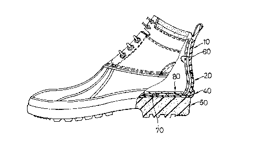
Figure 3 is a sectional view of the boot
produced according to the method of this invention;
Figure 4 is an inverted view of the boot produced
according to this invention, illustrated prior to
attachment of an outsole;
Figure 5 illustrates how an inner liner assembly is
inserted into the boot according to this invention;
Figure 6 is a cutaway view of the boot shown in
Figure 5;
Figure 7 is a block diagram of the method of this
invention;
Figure 8 is a sectional view of a modified
embodiment according to this invention; and
Figure 9 is a sectional view of another modified

~ 2 02200 006
embodiment according to this invention.
BACKGROUND OF THE INVENTION
As illustrated in Figure 1, the conventional
method of forming a boot comprises the steps of:
(a) molding the outsole 4 integrally with the lower
3 so as to form a unitary construction from a
waterproof polymeric thermosetting material;
(b) forming an upper 1 from a relatively flexible
material, the upper having a lower peripheral edge
stitched to an upper peripheral edge of the lower 3 to
form a seam juncture 5; and
(c) coating the inner surface of the seam juncture
with a waterproof layer.
Because the seam juncture 5 is spaced from the top
of the boot at a considerable vertical distance, it is
relatively difficult to insert the tool for coating the
waterproof layer on the seam juncture through the upper
portion of the boot.
In addition, because the lower 3 is made from the
same material as that of the outsole 4, which in turn
is generally made from hard and abrasive resistant
rubber to be able to withstand wearing, the boot is
relatively heavy, thereby easily causing fatigue to the
wearer.
SUMMARY OF THE INVENTION
Therefore, an object of this invention is to
provide a method of making a boot, wherein the sole of

~ _-3--0 2 2 0 0 0 0 6
the boot is connected to the lower after the lower is
connected to the upper so that a waterproof layer can
be provided at the seam between the upper and the lower
conveniently through the uncovered lower opening of the
lower.
Still another object of this invention is to
provide a method of making a boot whose lower is made
of a material of lighter weight than that of the
outsole so that the boot is relatively light in weight
and is more comfortable to wear as compared to the boot
produced according to the conventional method.
Accordingly, the method of making a boot in the
present invention comprises the steps of:
(a) forming a lower of unitary construction from a
first waterproo~ polymeric material, the lower
defining an enclosed toe zone and a heel zone and
having a first upper end portion defining a first upper
opening, and a first lower end portion defining a sole
opening;
(b) formi~g an upper from a relatively flexible
material, the upper having a second lower end portion
of a size such that the first upper end portion can be
smoothly seamed to the second lower end portion;
(c) joining the second lower end portion with the
first upper end portion of the lower to form a seam
juncture;
(d) applying a waterproof layer onto the seam

~ __4_0 ~ 2 0 0 0 0 6
juncture through the sole opening; and
(e) connecting a sole to the first lower end
portion of the lower in a water-tight relationship so
as to close the sole opening after step (d). A
water-tight seal may be formed by providing a
waterproof layer at the adjoining surfaces of the lower
and the sole or by injection molding the sole in the
presence of the lower to form the sole integrally with
the lower.
DETAILED DESCRIPTION OF THE PREFERRED EMBODIMENTS
Referring to Figures 2, 3 and 4, the preferred
embodiment of a boot according to this invention
includes a horizontally extending outsole 50, a shell-
like lower 20 disposed on the outsole 50, and an upper15 10 connected to an upper section of the lower 20 so as
to form the boot.
According to this invention, the method of making a
boot includes the following steps:
Step (a): A lower of unitary construction is molded
from a first waterproof polymeric material, such as PU
elastomer (polyurethane) or PVC elastomer (polyvinyl
chloride~ or rubber. The lower 20 defines an
enclosed toe zone 22A, a metatarsal zone 22B and a heel
zone 22C. The lower 20 further has a first upper end
portion 22E defining a first upper opening and a first
lower end portion 22D defining a sole opening. In the
preferred embodiment, the first upper opening of the

0 2 2 0 0 0 0 6
lower 20 extends from the metatarsal zone 22B to the
heel zone 22C while the sole opening thereof extends
from the toe zone 22A to the heel zone 22C.
(b) An upper lO is formed from a relatively
flexible material, such as waterproof leather and the
like which is generally lighter compared to the lower
20. The upper 10 has a second lower end portion lOP
of a size such that the first upper end portion 22E of
the lower 20 can be smoothly seamed to the second lower
1.0 end portion lOP. The upper 10 further includes two
spaced eyelet tabs lOX and a tongue (not visible) which
has a lower section stitched to the lower 10 and two
parallel edges stitched to the eyelet tabs lOX, thereby
forming a plurality of seam junctures 11.
(c) The second lower end portion loP of the upper
lO is stitched to the first upper end portion 22E of
the lower 20, thereby forming a seam juncture 23.
(d) The seam juncture 23 is sealed so as to be
waterproof by applying a layer of waterproof material
onto the seam juncture 23 through the sole opening of
the lower 20. The waterproof layer may be provided by
coating the seam juncture 23 with a waterproof coating
or by adhesively attaching a tape of waterproof
materia1 to the seam juncture 23 so as to cover the
seam juncture 23. Note that the sole opening at the
first lower end portion 22D of the lower 20 is wide
enough to permit easy access to the inner surface of

,~ 6 02200 006
the seam junctures during coating of the seam junctures
11 and 23. Thereafter, an insole 30 of non-waterproof
fabric is attached by a conventional method to the
first lower end portion 22D of the lower 20. A seam 31
is formed between the insole 30 and the lower 20.
(e) An outsole 50 is molded from a second
waterproof polymeric material, such as an abrasion
resistant rubber, which is harder when compared to the
first waterproof polymeric material. The outsole 50
~0 has a shape corresponding to but is slightly larger
than the cross-section of the first lower end portion
22D of the lower 20.
(f) A waterproof layer 40 of thermosetting material
is provided between the adjoining surfaces of the
peripheral portion 51 of the outsole 50 and the insole
30 and between the adjoining surfaces of the peripheral
portion 51 and the lower end portion 22D of the lower
20. The water proof layer 40 may be provided by
applying a waterproof coating or by adhesively
attaching or injecting and curing a waterproof
material. A waterproof seal is thus formed between the
f irst lower end portion 22D of the lower 20 and the end
portion 51 of the outsole 50, so that water cannot seep
into the interior of the boot.
As illustrated in Figures 5 and 6, a liner 60,
which has a shape conforming to that of the inner
surface of the combined upper 10 and lower 20, can be

02200 006
~ __7__
stitched to a second upper end portion lOQ of the upper
10. The liner 60 is then inserted interiorly of the
boot so that the liner 60 snugly fits in the boot.
When desired, a foot-like padding 80 can be removably
disposed at the bottom 70 of the liner 60.
Referring to Figure 8, in another preferred
embodiment o~ this invention, an outsole 50' is formed
by injection molding in the presence of the lower 20 so
that the outsole S0' is formed in integral with the
~ 10 lower 20. The outsole 50' has a peripheral portion 51'
to surround the lower end portion of the lower 20. The
injection molding may be conducted in a mold tnot
shown) by first mounting the lower 20 on the mold and
then injection molding the outsole 50' so that the
peripheral portion 51' of the outsole 50' is integrally
connected to the lower end portion 22D of the lower 20
in a water-tight relationship.
Referring to Figure 9 illustrates a still another
preferred embodiment of the present invention wherein
the peripheral portion 51" o~ the outsole 50", which
projects upwardly, is adhesively connected to the lower
end portion 22D. A waterproof coating 40" is applied
at the top end of the peripheral portion 51" of the
outsole 50" and the adjacent surface of the lower end
2S portion 22D of the lower 20 to provide a water-tight
sealing.

Representative Drawing
A single figure which represents the drawing illustrating the invention.
Administrative Status

2024-08-01:As part of the Next Generation Patents (NGP) transition, the Canadian Patents Database (CPD) now contains a more detailed Event History, which replicates the Event Log of our new back-office solution.

Please note that "Inactive:" events refers to events no longer in use in our new back-office solution.

For a clearer understanding of the status of the application/patent presented on this page, the site Disclaimer , as well as the definitions for Patent , Event History , Maintenance Fee  and Payment History  should be consulted.

Event History

Description Date
Time Limit for Reversal Expired 2011-03-14
Letter Sent 2010-03-15
Inactive: Payment - Insufficient fee 2007-05-23
Inactive: Late MF processed 2007-05-02
Letter Sent 2007-03-14
Inactive: IPC from MCD 2006-03-12
Inactive: Office letter 2001-12-07
Grant by Issuance 2000-05-23
Inactive: Cover page published 2000-05-22
Inactive: Final fee received 2000-02-22
Pre-grant 2000-02-22
Letter Sent 1999-10-26
Notice of Allowance is Issued 1999-10-26
4 1999-10-26
Inactive: Approved for allowance (AFA) 1999-09-29
Amendment Received - Voluntary Amendment 1998-10-07
Application Published (Open to Public Inspection) 1998-09-14
Letter Sent 1998-07-24
Request for Examination Received 1998-03-25
Request for Examination Requirements Determined Compliant 1998-03-25
All Requirements for Examination Determined Compliant 1998-03-25
Inactive: IPC assigned 1997-07-31
Inactive: First IPC assigned 1997-07-31
Small Entity Declaration Determined Compliant 1997-03-14

Abandonment History

There is no abandonment history.

Maintenance Fee

The last payment was received on 2000-02-22

Note : If the full payment has not been received on or before the date indicated, a further fee may be required which may be one of the following

  • the reinstatement fee;
  • the late payment fee; or
  • additional fee to reverse deemed expiry.

Patent fees are adjusted on the 1st of January every year. The amounts above are the current amounts if received by December 31 of the current year.
Please refer to the CIPO Patent Fees web page to see all current fee amounts.

Fee History

Fee Type Anniversary Year Due Date Paid Date
Application fee - small 1997-03-14
Request for examination - small 1998-03-25
MF (application, 2nd anniv.) - small 02 1999-03-15 1999-03-11
MF (application, 3rd anniv.) - small 03 2000-03-14 2000-02-22
Final fee - small 2000-02-22
MF (patent, 4th anniv.) - small 2001-03-14 2001-03-06
MF (patent, 8th anniv.) - small 2005-03-14 2001-11-23
MF (patent, 9th anniv.) - small 2006-03-14 2001-11-23
MF (patent, 5th anniv.) - small 2002-03-14 2001-11-23
MF (patent, 6th anniv.) - small 2003-03-14 2001-11-23
MF (patent, 7th anniv.) - small 2004-03-15 2001-11-23
MF (patent, 11th anniv.) - small 2008-03-14 2007-05-02
Reversal of deemed expiry 2007-03-14 2007-05-02
MF (patent, 10th anniv.) - small 2007-03-14 2007-05-02
MF (patent, 12th anniv.) - small 2009-03-16 2007-12-05
Owners on Record

Note: Records showing the ownership history in alphabetical order.

Current Owners on Record
EDDIE CHEN
Past Owners on Record
None
Past Owners that do not appear in the "Owners on Record" listing will appear in other documentation within the application.
Documents

To view selected files, please enter reCAPTCHA code :


To view images, click a link in the Document Description column (Temporarily unavailable). To download the documents, select one or more checkboxes in the first column and then click the "Download Selected in PDF format (Zip Archive)" or the "Download Selected as Single PDF" button.

List of published and non-published patent-specific documents on the CPD .

If you have any difficulty accessing content, you can call the Client Service Centre at 1-866-997-1936 or send them an e-mail at CIPO Client Service Centre.


Document
Description 
Date
(yyyy-mm-dd) 
Number of pages   Size of Image (KB) 
Cover Page 2000-04-24 1 32
Cover Page 1998-10-22 1 33
Description 1997-03-13 7 236
Abstract 1997-03-13 1 9
Drawings 1997-03-13 9 115
Claims 1997-03-13 2 51
Representative drawing 1998-10-22 1 12
Representative drawing 2000-04-24 1 13
Acknowledgement of Request for Examination 1998-07-23 1 194
Reminder of maintenance fee due 1998-11-16 1 110
Commissioner's Notice - Application Found Allowable 1999-10-25 1 164
Maintenance Fee Notice 2007-04-24 1 172
Late Payment Acknowledgement 2007-05-22 1 166
Maintenance Fee Notice 2010-04-25 1 170
Correspondence 1997-03-13 1 28
Correspondence 2000-02-21 1 30
Fees 2000-02-21 1 37
Fees 1999-03-10 1 42
Fees 2001-03-05 1 32
Fees 2001-11-22 2 48
Fees 2001-12-26 1 24
Fees 2007-05-01 2 46
Fees 2007-12-04 1 25