Note: Descriptions are shown in the official language in which they were submitted.
2200323
A process for the productioll of moltell pi~ iron or steel pre-pro(luct.~; an(t a plant for carryin~
out the process
The invention relates to a proce!is for thé pro~tuctioll of moltell pig iron or steel pre-products
from fine-particulate iroll-contaillin~ material, in particul;lr re~luced sponge iron, in a melt(lown
gasifying zone of a melter gasifier, in which, under tlle supply of carbon-containing material
an(t oxygell-colltaillillg gas at the silnultaneou.s formatioll of a reducing gas, the iron-colltaining
material is melted in ~ bed forme(l of soli(t carboll carriers, optionally upon previous complete
re(tuction, and a plallt for cal-ryill~ out the proces.s.
EP-B - () 01() 627 teaches a process for the productioll of moltell pig iron or steel pre-pro(lucts
from particulate iroll-colltainillg material, particularly prere(tuce(l sponge iron, and for the
production of reducing ga~s in a melter ga.sifier, whereill by the a(l(litioll of coal and by blowing
in an oxygen-colltailling gas a fluidize(l bed is formed of col~e particles~ Here, the oxygen-
containing gas or pure oxygell respectively are injected hlto the lower region of the melter
gasifier~ The particulate iron-containing material, particul.lrly prereduce(l sponge iron, and the
lumpy coal are fect in from above, throu~ll chargillg openillgs arrange(l in the hoo(l of the
melter gasifier, the descell(ling particles are slowe(l dowll hl the fluidize(l bed an(l the iron-
containing particles are reduce(l all(l nlelte(l while fallillg throu~ll tlle coke fluidize(l bed~ The
molten an(l ~slag-covere(l metal collects at the bottom ol' the melter ~asifier. Metal and slag are
drawn off through separate tap openill~s.
A process of this kin(l i.s, however, not suite(l for processill~ tine-particle sponge iron, as fine-
particle sponge iroll woukl be discharge(l from melter gasifier at once, due to the pronounced
gas flow existing withhl the same. Dischar~ing is further promote(l by the temperature reigning
in the upper region of the melter gasifier, sillce it is too low to ensure meltillg of the sponge
iron at the charghlg site.
From US-A - 5,()~2,251 it is knowll to directly reduce iron-collt;lining fine ore in a fluidized
bed operation by mealls of a reducill~ gas pro(luced from natural gas. In thhs process the fine
ore, which is rich in iron, is reduce(l by means of a reducillg ga.s, at elevated pressure, in a
system of fluidized bed reacton~ arrange(l hl series. The spollge iron powder thus obtained is
subse(luelltly subjecte(l to hot or col(l bri(~uettin~. For furtller processillg the sponge iron
pow(ler, separate meltill~ f~cilitie.~ have to be provide(l.
From EP-A - O 217 331 it is knowll to (iirectly prere(luce fine ore in a fluidize(l bed process
and to feed the prere(luce(l fine ore to a melter ~asifier all~l to completely reduee it by means of
~ 2 2200323
a plasma burner under the supply of a carbon-contailling recluciIlg ageIlt and to melt it In the
melter gasifier, a fluidize(l bed t'orms all(l thereabove a fluidize(l bed of coke The prereduced
fine ore or the sponge iron pow(ler respec tively are supplie-l to a plasma burner provided in a
lower secti()n of the melter ga!,ifier One (lisa(lvalltage llere is that by feeding the prereduce(l
fine ore imme(iiately in the lower melting regioll, i e in tl-e regioll where tlle melt collects,
complete reductioll is no klllger ensure(l an(l the chemical composition re(luired for further
processing of the pig iron C;lllllOt be achieve(l in any event Moreover, charging of substantial
amounts of prereduce(l fine ore is n(lt feasible, due to the fluidize(l bed or fi,Ye i bed
respectively forming from coal in the lower region of tlle melter gasifier, as it is not feasible to
clischarge a sufficiellt portion of the meltillg pro(lucts from the high-tclnperature zone of the
plasma burner Chargil1g of more substantial amoul1ts of prereduce(l fine ore would instantly
lea(l to thermal an(l mecl1allical failure of tlle plasll1a burner
From EP-B - O 111 176 it is known to produce sponge iroll particles and molten pig iron from
lumpy iron ore, the iron ore behlg directly reduced in a clirec t-reclucti(ln aggregate and sponge
iron particles discharged from the direct-reduction aggregate being separated into a coarse-
and fine-grain fraction The fine-grain fracti(ln is supplie-l to a melter gasifier, in which the heat
required for melting the spollge iron as well as the reducillg gas supplied to the direct-
redu~tion aggre~ate ~re produ~ed from ~hargc(l coal ~uld supylied oxygell-colltaining gas The
fine-grain fraction is collducted intO the melter g~sifier via a downpipe projecting from the
head of the melter ga~sifier as far as into tlle viCillity of tlle fluidized bed of coal At the end of
t'ne downpipe a baMe plate is provi(led in or(ler to minimize the velocity of the fine-grain
fraction, and conse~luelltly the eYit velocity of the fhle-graill fraction on leaving the downpipe
is very low At the chargillg site, the temperature reigllillg insicle the melter gasifier is very low,
as a result of which immediate melting of the supplie-l fine-grain fraction cannot take place
This and the klw exit velocity frolll the dowllpipe lea(l to a substantial portion of the supplied
fine-grain fraction exiting frolll the melter gasifier alollg with the reducing gas produced in the
same In acc(lrdallce with this process it is not pos!iible to charge a more ~substantial amount of
fine grain or to cllarge fine graill e,Yclusively
In a process accor(ling to EP-A - () 57(~ 414 lumpy iron-ore-containing charging substances are
directly redueed in a reduction ~haft furnace, by means of the reducing gas formed in the
meltd(lwn ga~sifyillL~ zc)lle The spollge iron thus clbtainecl is subse~luently fed to the meltclown
gasifying zone In order to be able to additionally utilize fine ore and/or ore dust, such as
o,Yidic iron fine dust incurring in a metallurgical plant, with this known process, the fine ore
and/or the ore dust alollg with solid carboll carriers are supplied to a clust burner working into
the meltdown gasifying zolle ancl are reacted in a substoichi(lmetric cormbustion reaction A
~ 3 2200323
process of this kind enable~ efficient proce~ lg of fine ore alld/or ore du~t incurring in a
metallurgical plant, alld that up to all order of magnitu(le of 2(1 to 3() ~/~ of the total ore charge,
and thus enables a c ombille(l processillg of lumpy ore alld fine ore
The inventioll aims at avoidillg these drawbacks an(l ~lifficulties and has as its object to provide
a process of the initially describe-l kin(l and a plant for carrying out the process enabling the
processing of fine-particulate iron-colltaining material, without any need for briquetting, and
wherein on the one llalld any discllarge of the supplied fhle particles, i e of the iron-containing
material, optiollally in the prereduce(l or in the colllpletely reduce(l state, by means of the
reducing gas produce(l hl the melter gasifier i~; reliably avoi(le(l an(l wherein on the other hand a
possibly required complete reductioll is en~ure(l One particular object of the invention is to
create a process enabling the proces~illg of a charge the majority of which, preferably 100 %,
are made up of fine-particul;lte iron-c(llltaillillg material to obtain pig iron and/or steel pre-
products, while utilizing a melter gasifier
According to the invelltion this object is achieved in that the iroll-colltaining material is
supplied into the a melter gasifier centrally, closely above the bed but in its immediate ViCillity,
by means of an oxygen-burner un(ler the formation of a lligh-temperature combustion zone,
wherein prefer~bly a burnillg jet forme(l hl tlle lligh-telllper;lture combustioll zone is directed
towards the surface of the be-l an(l is utilized for blowhlg tlle iron-colltailling material towards
the surface of the bed
On the surface of the bed the velocity of the fine-particulate iroll-colltaining material is slowed
down, so that a retention time is acllieve(l in the high-temperature zone that is sufficient for
melting the supplied iron-containillg materiak Slag and iron can run off through the fluidized or
fixed bed respectively toward the lower section of the melter gasifer Due to the retention time
ensured in the meltdown gasifying zone complete reductioll of any iron-containing material not
yet completely reduced at thi~ stage is ensure~l
From EP-A - O 174 291 it is known to supply (~ustiike sulfidic nonferrous metal ores,
particularly nonferrou~; metal ores, to a melter gasifier via a melter-burner Even more
substantial amounts of sulfi-lic nollferrous metal ores C;lll be processed here, as the heat
re~luired for melting the ore particle~; is produced by exotherlllic reaction of the sulfidic ore
with o,xygen in tlle bumer
With this known process, the coal for forming a fluidized bed of carbon is charged into the
meltdown gasifyin~ zone separately With a process of this kind it is not feasible to oxidic fine
2200323
ores, as the heat that would cause these oxiclic fine ores to rnelt would not be available here.
As a result, due to the fine ore supply duct being arrange~l at the upper end of the melter
gasifier, these fine ores would be discharged by the reducing gas which emerges from the
meltdowll gasifying zone alld is di.scharged from the melter gasifier.
To prevent the fine-particulate iroll-colltainillg material cllargecl into tlle meltdown gasifying
zone from being o,Yidize~l by the oxygen or o,Yygen-colltailling, gas supplied to the oxygen
burner, according to the hlvelltioll advalltageously fine ~oal is introduced, or preferably blown
into the high-temper~ture combu.~.tioll zone directly.
Accordillg to a preferred embodilnellt fine ore is re(lu(:e(l in tlle fluidize(l bed process by means
of the reducing gas forme(t in the melt(lowll gasifyillg zone, wherein the reducing gas emerging
from the melter ga.sifier is collveyecl to the fluidized bed reductioll clirectly, i.e. without prior
dust separation. In the process, the coke clust discllarge(l from the meltdown gasifying zone
along with the reducing ~as is fed to the fluidize(l bed reductioll zone ancl thereby reduces the
danger of "sticking". Alollg with the reduce(l fine ore it is subsequently fed to the meltdown
gasifying zone agaill, via the oYygell bumer, so that it will not be lost.
Advantageously lumpy carboll-colltaillillg material as well as lumpy iron-containing material,
which, in view of their size, callllc)t be discllar~e(l along with the gas stream, are a(l(litionally
introduced into the meltdowll gasifyillg zone via supply ducts leaclillg into the upper section of
the melter gasifier. Thus with the process ac(:or(lillg to the invention conventional melter
gasifiers may be employe(l without ally major collstructiollal cllallges.
A plant for carrying out the process, comprising a melter gasifier includillg supply and
discharge ducts for adding c arbon-containing material, iron-containing material, for
discharging the reducing gas pro(luce(l ancl for feec~illg oxygen-containing gas, as well as a slag
and iron-melt tap, wherehl a lower section of the melter gasifier is provided for collecting the
molten pig iron an~l the li(luid slag, a superimpose(l central s ectioll i~ provided for
accornmo(l~ting a be(l of soli(l carboll carriers an(l subse(luently all upper section is provided as
a killing space, chara(:terized in that a burner supplying an oxygen-collt;lillillg gas an(l fine-
particulate iron-containing m~terial int( the melter gasifier is provided whose burner head is
arranged at the transition from the central sectioll to the upper sectioll in the heart of the cross
sectioll of the killing spa(:e, wherein suitably tlle bumel hea(l is directed towarcls the surface of
the bed.
2200323
~ 5
Preferably, lance openillgs of supply lances feeding fine coal are provi(led in the immediate
vicinity of the burner llead.
In a(:cor(lance witll a preferred enlbo(lilllellt the bunler i.~i (le~iglle(l a.~ a burning lance
proh-uding into the interior of the melter gasifier vertically and celltrally, departillg from the
head of the melter gasifier. The burner may for example be con~structed as described in EP-A -
0 481 ~?55. In additioll it may be provided with all anllular gap for shnult;lneously supplying
solid fine-particle coal.
Suitably the supply lallce.~ protru(le into the melter gasifier departillg from the side, preferably
slanting downward.
It is of advantage if, departing from the killhlg space of the melter gasifier, a reducing-gas
discharge duct runs directly, i. e. with no dust separatillg means arrallged interme(liately, into a
fluidized bed reactor utilized for directly reducillg fhle-p.lrticul;lte iron ore, and that departing
from the fluidized bed reactor a duct for disch;lrging reduce(l fine ore run.s into the burner.
In the following, the invention is explaine(l in more detail with reference to an exemplary
embodiment represente(l schematically in the drawillg.
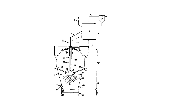
The plant according to the hlvelltion is provided with a fluidized bed reactor 1, into which iron-
containing ~lne nre or iroll-cnnt;lillill~ ore (f.i. 1~61 kg ore/ton pig iron) containing a
considerable portion (more thall 5() ~) of fine ore i.s fed through an ore feed duct 2. In this
fluidized bed reactor I a pre- or nptiollally a complete reduction of the fine ore is carried out in
a fluidized bed zone 3.
Detail~s concerlling the ore:
Fe"" ~6.3 C~r
Fe,O~ '~4.7 ~r
grain size 0 to X mm
Instead of the single fluidized bed reactor I it is feasible to provide several fluidized bed
reactors consecutively arranged in .series, whereill the fine ore is conducted from fluidized bed
reactnr to fluidize(l bed rea(:tor via conveyillg ducts. silllilar to the manner described in US-A -
5,()X2,25 1 .
~, " 2200323
The pre- or completely re~iuee(l fine ore, that is to say the spol1~e iron pow(ler (530 kg/ton pig
iron), is supplie(~ to a melter ~asifier S tl1rou~11 a eonveyil1~ duet 4, in a mal1l1er that will be
describe~i in more detail below~ In the n1elter ~asifier 5, in a melklowl1 gasifying zone 6. a CO-
and H7-eontainin~ redu(:il1g ~as (1715 Nm-/tol1 pi~ iron at X5()"C) is produce(l fromeo;ll and
oxygen-(:ontainin~ ~as and i~ fe(~ to the fluidize(l bed reaet()r I via a reducil1g-gas feed duet 7
Analysis of the reduein~ ~s:
CO 63~4 "~
CO7 4~3 ~t/"
H7 2t~3 ~
balance (H70, I'17, CH~)
The redueil1~ gas then stre;ll11s throu~l1 the fluidize(l be(l reactor I in eounterflow to the ore
flow an(l is dischar~e~l fro m the flui(lize(l bed rcactor I via a top-~as disel1arge duct 8 and
subsequently is cooled an(l scrubbe(t in a wet scrubber ~ and then is made available to
consumers as a top ~as (1~3'~ Nml/ton pig ir()n).
Analysis of the top ~as:
CO 42 c~"
CO~ 33.2 %
H7 18.4 '7~
balance (H,O, N7, CH~)
calorific value of the top ~s: 7~1 kJ/m normal
The melter ~a.sifier S is provide~l with supply (luets I() for soli(l carbol1 carriers in lumpy form
(7()() k~ lump eoal/tol1 pi~ iron), .~iupply (luet.~i I I for oxy~el1-eol1t;lil1il1~ ~ases (275 Nm3 OJton
pig iron) as well as optionally supply duets for earbol1 earriers, sU(:h as hydro(:arbons, that are
liquid or ga~eous at room temperature as well as for burned fluxes.
In the melter gasifier 5, in a lower sectiol1 I below the melt~lown ~asifying zone 6, molten pig
iron 12 (10()~ k~ pi~ iron/ton pig iron) or molten steel pre-material respeetively and molten
sla~ 13 (3()3 kg/ton pi~ iron) colleet, whieh are tapped off via a tap 14.
The average analysis o f the pig iron is as follows:
C 4.3 '7,~
Si 0.4'i~
~ 7 2200323
Mn 0 0X ~/,
P (). I ~/,.
S 0 ()5 'i~
balance (Fe)
Average slag basicity B2 (CaO/SiO~) = l 1
In a section Il of the melter, gasifier S arranged above the lower section I a bed 16 is formed
from the solid carbon carriers, preferably a fi~ced bed and/or a fluidize(l bed The upper section
III provided above the central sectioll 11 serves as a killing space for the reducing gas forming
in the melter gasifier 5 and for solid particles entrained by the ga~s strealll forMed by the
reducillg gas.
The pre- or completely reduced fine ore is introduce(l hlto the melt(lown gasifying zone 6 by
means of an oxygen bumer 15 directed dowllwar(l from above all(l oriented approximately
vertically, with the burner head 15' being positiolle(l closely above the surface 17 of the bed
16 With respect to the cross-se(:tion of the Melter gasifier 5 the burner head 15' is arranged in
the central region of the same, i e spaced apart from the side wall of the same Preferably only
a single burner head 15' is provided, which is positioned On the vertical longitudinal center line
of the Melter gasifier 5 The burner 15 is provided with a central inner pipe 18 for feeding the
partially or completely reduce~l fine ore and with an anllular gap 2() for feeding oxygen (275
Nm~ OJton pig iron) or an oxygell-contailling gas respectively, whicll ~surrounds the central
inner pipe 18 and is delimited by a cooled outer pipe l'~
At the exit site of the o~cygell-(:ontaillillg gas and of the supplied iron-containing material a
high-temperature combustiol1 zone 21 is formed h1 WhiCIl the iron-colltaillillg material blown in
via the burner hea~l in the ~lirectioll of the surface 17 of the bed If), due to bein~ slowe~ down
on the surface 17 of the bed 1~ and by impinging On tlle said surface 17, reaches a retention
time that is sufficiellt for meltin~ the iron-contaillil1g material The slag thus formed and the
molten iron can run off througll the bed lG to the lower sectioll I of the melter gasifier 5
It may be of advalltage, particularly in case of major fluctuations in the grain size of the
charged fine ore or in case a certain portion is Made up of coarser ore particles, to fractionate
the iron-containing material emerging from the flui~iized bed reactor 1 and to feed only the
fine-grain fraction to the burner 15 while charging the coarse-grain fraction (preferably 2 to 8
mm) (530 kg/ton pig iron) via a sep;lrate supply (luct 22 anu supply openings 23 in the upper
~ x 2200323
section of the melter gas,ifiel- S hltO the sal1le. Preferably, tl-e gr;lil1 .size of the particles supplied
via the burner 15 ral1ges fronl () to 2 Inm.
Details concerning the coal:
ultimate analy.si.s:
C 73.6 ~/~
H 4.4 ~7r
N 1.7
0 6.2 ~/~
S 1.() 5
Cfi,Y
volatile.s 25.
ashes 8.6 ~
grahl size of the fine coal:
Oto2mm
grain size of the lump c()al:
8 to 50 mm=
In close vicinity of the burner head 15', lance openhlgs 24 are positioned of supply lances 25
supplying fine coal (25() kg/ton pig iron). Thu.s it becomes feasible to blow fine coal into the
high-temperature combustion zone 21 from tlle side to a level below the burner heacl 15',
thereby making it possible to prevent o,Yidatioll of the partially or completely reduced fine ore
by the oxygen .supplied via the bun1er hea(l 15'.
The supplied fine c(1al further enables a reductioll h1 the tel1lper.lture of the reducing gas
forme(l in the meltd(.)wl1 gasifyillg zone ~, whicl1 then cal1 be discllarged like in conventional
melter gasifiers,.
A dust separating means becomes unllecessary for the reducing gas as well as a dust recircling
means, since in the fluidized-bed reduction zone 3 of the fluidized-bed reactor 1 the coke dust
discharge(i along with the reducil1g gas reduces the danger of "sticking", al1d thus is by no
means disturbing and via the oxygell burner 15 reaches the meltdown gasifying zone 6 again. It
may be advantageous, however, with a view to adjustillg the temperature of the reducing gas,
to purify a portion of the same alld subse(luently recircle it.