Note: Descriptions are shown in the official language in which they were submitted.
~2~064D
FILM FOR MULTIPLE BAG
BACKGROUND OF THE INVENTION
Field of the Invention
This invention relates to a film for a multiple
bag composed of at least two sheets of film which are not
laminated to one another and can freely be mutually
slipped, said film for a multiple bag being used for
automatically making a bag and packing the bag with a
liquid, a semifluid, a powder or the like for business
use, the multiple bag obtained therefrom being excellent
in mechanical characteristics such as pinhole resistance,
drop impact strength and the like and the said film for a
multiple bag being much superior in workability in an
automatic bag-making-and-packing machine.
Description of the Related Art
Materials such as liquid, semifluid, powder and
the like for business use have heretofore been packed in
a metal container and then put to distribution including
transportation, custody, sale and the like. However,
metal containers are disadvantageous in that they are
bulky even after use, the contents of the containers are
difficult to take out, the treatment of the containers
after use is difficult, etc.
A packaging method called "in-box" by which the
- 1 -
zz~os~~
above contents are packed in a plastic-made bag and the
thus packed bag is placed in a corrugated box and
distributed is now being widely put to practical use.
In the case of packed bags for the in-box, it
is preferable to effect the packing by an automatic bag-
making-and-packing machine in view of the efficiency of
the contents-packing. On the other hand, the packed bag
contains a large weight of contents and has a large size,
and hence, is required to have a high mechanical
strength. Also, the contents are often fluids, semi-
fluids or powders which are easily escaped from a small
rent of the container and are, once escaped, difficult to
treat, and the packed bag is required to have mechanical
strength characteristics such as drop impact resistance,
pinhole resistance, cold resistance and the like.
In order to increase the strength of the packed
bag, there is well-known a method in which high-strength
films of nylon, polyester or the like are laminated
through a fusible layer. For further enhancing the
strength, it is possible to laminate other various films
or increase the thickness of the high-strength film;
however, the extreme increase of the thickness of the
film hardens the film, and as a result, the flexure
stress applied to the film is increased, the flexural
fatigue, pinhole resistance and drop impact resistance
are deteriorated, and the packing workability is lowered.
- 2 -
Therefore, at present, the above problem cannot be solved
by only increasing the thickness of the film.
Under such circumstances, there has been
proposed a multiple bag in which the films constituting
the bag are not laminated and are in the mutually movable
state. In the case of this multiple bag, even when a
pinhole is formed in one sheet of film, the other sheets
of film are flaw-free, and even when one independent
sheet of film receives the flexure stress another sheet
of film can be slipped to be escaped from the flexure
stress, so that there is no fear that an extreme large
flexure stress may be applied. Therefore, the bag has
excellent mechanical strength characteristics and is
excellent as a bag for the bag-in-box.
However, when diverse films are merely put on
one another and rolled in an automatic bag-making-and-
packing machine, the films cause position deviation and
winding breakage, and hence, this method has been by no
means put to practical use.
Accordingly, a multiple film in which films are
merely put on one another cannot be used in an automatic
bag-making-and-packing machine, and hence, the multiple
bag actually used is employed in a system in which bag-
making and packing are separately carried out, that is, a
system in which a previously prepared multiple bag with a
tap is packed with the contents introduced through the
- 3 -
tap. This system is inferior in working efficiency and
it is unavoidable for air to remain in the sealed bag.
Hence, there is such a fear that the remaining air may
accelerate the deterioration of the contents.
On the other hand, there is proposed a method
in which diverse films are previously continuously fused
at their both-side edge portions to one another and then
fed to an automatic bag-making-and-packing machine.
However, even in this method, the diameter of a roll
formed by winding the inside film and the diameter of a
roll formed by winding the outside film are delicately
different, and hence, when the films are wound
repeatedly, said delicate difference in diameter results
in a wrinkle and a sag and when the films wound up become
disordered, so that only a small roll of film can be
provided, and owing to a frequent roll-exchange, at
present, the workability as a whole is not enhanced.
In addition, this method comprises a step of
fusing both-side edge portions of the films and this step
requires a given heating time and hence requires a long
period of time as a whole for the processing. Therefore,
the method is not practical.
Thus, there have been required films from which
a multiple bag can be easily produced using an automatic
bag-making-and-packing machine.
- 4 -
CA 02200640 2000-02-O1
SUMMARY OF THE INVENTION
According to this invention, there is provided
a multiple film for a multiple bag, the multiple film
comprising at least two sheets of film put one on anoth-
er, and having scattered along its both-side edge por-
tions spot-fused portions by which at least two sheets of
film are partially united, the spot-fused portions pref-
erably having irregularities on their surfaces or a group
of fine scars provided densely on their surfaces.
According to this invention, there is further
provided a process for producing a packed multiple bag,
which comprises a step of forming a multiple film by
putting at least two sheets of film one on another, a
step of discontinuously providing spot-fused portions
along both-side edge portions of the multiple film, by
which spot-fused portions the at least two sheets of film
are partially united, a step of fusing the multiple film
in the longitudinal direction to form a cylindrical film,
a step of packing contents in the cylindrical film and
fusing the cylindrical film in the transverse direction,
and a step of cutting the fused portion in the transverse
direction.
This invention further provides an apparatus
for producing a packed multiple bag, which comprises a
film-feeding means having at least two film-feeding
rolls, a means for fusing in the longitudinal direction,
- 5 -
220U6~u
a means for packing contents, a means for fusing in the
transverse direction, a means for cutting the fused
portion in the transverse direction, and a spot-fusing
means for intermittently fusing at least two films fed
from the said at least two film-feeding rolls in the
state that the films are put one on another, along their
both-side edge portions, the spot-fusing means being
provided between the film-feeding means and the means for
fusing in the longitudinal direction.
BRIEF DESCRIPTION OF THE DRAWINGS
Fig. 1 is a perspective view of a film for a
multiple bag which film is an example of this invention.
Fig. 2 is an enlarged descriptive view of an
example of the spot-fused portion of the film of this
invention.
Fig. 3 is an enlarged descriptive view of
another example of the spot-fused portion of the film of
this invention.
Fig. 4 is an enlarged descriptive view of a
further example of the spot-fused portion of the film of
this invention.
Figs. 5A and 5B are enlarged descriptive
sectional views of scars in the side edge portion of an
example of the multiple film of this invention wherein
Fig. 5A shows a scar having a through-hole and Fig. 5B
- 6 -
z2oos,~~
shows a through-hole-free scar.
Fig. 6 is an outlined view of the apparatus for
producing a packed multiple bag of this invention.
Fig. 7 is a sectional view of a hot pin roll.
Fig. 8 is a sectional view of the hot pin roll
at the III-III line in Fig. 7.
Figs. 9A and 9B are sectional views showing the
specific shapes of the hot pin.
Fig. 10 is a sectional view of a intermittently
fusing means having other hot pins.
Fig. 11 is a sectional view of another inter-
mittently fusing means free from hot pins.
Fig. 12 is a perspective view of an example of
an automatic bag-making-and-packing machine.
Fig. 13 is an outlined view of an example of
the apparatus for producing the rolled multiple film.
DESCRIPTION OF THE PREFERRED EMBODIMENTS
In this invention, by providing dot-like-spot-
fused portions on both-side edge portions of at least two
sheets of film which are not fused nor bonded to one
another and can be freely mutually moved, the at least
two sheets of film are partially and integrally fused
and, in the unfused portions, the at least two sheets of
film can be freely mutually moved.
As a result, it is possible to wind up or
22006~G
unwind the at least two sheets of film as one sheet of
film, and the irregularities formed by the spot-fusion
are mutually entangled to prevent winding breakage, to
assure the rolling of the film.
By allowing the spot-fused portions to be
present in the somewhat thick state in only the side edge
portions, the side edge portions of the film become
thick, when the film is rolled, in such a state that the
side edge portions rise as shown in Fig. 1. In general,
the film of the innermost layer and the film of the
outermost layer which are freely mutually moved are
slightly different in roll diameter and this difference
causes winding wrinkle. As a result, it becomes impos-
sible to roll the film under a give tension. However,
according to this invention, both-side edge portions of
the film are thicker than the other portions in the
rolled state and firmly rolled under the same tension, so
that the rolled film is tensionless and relaxed in the
center portions and the slight difference in roll diame-
ter of the film is absorbed by this relaxed state.
Therefore, the above-mentioned undesirable wrinkle and
sag due to the difference in roll diameter of at least
two sheets of film are not caused.
In this invention, the spot-fusions are used to
unite at least two sheets of film; however, since there
is some distance between one spot-fused portion and
_ g _
220064
another spot-fused portion, the portions which are not
spot-fused in both-side edge portions become spaces
between the spot-fused portions. This space can absorb
the slippage between the at least two sheets of film
which can be freely mutually moved.
Accordingly, even if the diverse films are
mutually wound neither wrinkle nor sage are caused and
the films do not cause blocking between them, whereby a
united multiple film can be smoothly unwound, so that the
at least two sheets of film can be subjected to automatic
bag-making and packing as if it is one sheet of film.
The spot-fused portions come to above or out-
side the fused portions of the bag during the bag-making,
and hence, they do not affect the air-tightness and
strength of the body of bag at all.
This invention in one aspect is a multiple film
in which at least two sheets of film are put one on
another, and in which the above-mentioned spot-fused
portions lie scattered along the side edge portions and
simultaneously a group of fine scars are provided so that
one of the films enter locally the adjacent film, whereby
projects are formed on the surface of the said adjacent
film. Moreover, in the film for a multiple bug of this
invention, it is preferable that at least one surface of
the film surfaces which are mutually adjacent and freely
movable is roughened.
- g -
22006~(~
By providing a group of fine scars in both-side
edge portions of at least two independent diverse films,
the film portions from which the scars project have a
wedge effect, whereby the films can be bonded to one
another in the side edge portions, to prevent the winding
breakage and to permit the films to be rolled assuredly.
The scars mechanically provided project to the other
surface, and hence, have such a function that at least
two diverse sheets of film are entangled and fixed. In
addition, when rolled, a freshly rolled film knocks
against the protrusions of the film rolled just before,
so that both side edge portions 48 are rolled in a thick-
er state as shown in Fig. 1. Furthermore, the protru-
sions are fitted in the concave portions of the next film
to form entangled portions, whereby the film is densely
rolled, so that the roll thus obtained has a less fear
that the winding is broken than a roll formed by densely
rolling merely the whole of a film in the width direc-
tion.
On the other hand, in the unwinding, the film
in the center portion which becomes the body of a bag is
rolled loosely, so that the slight difference in roll
diameter between at least two mutually freely movable
sheets of film is absorbed by this looseness. Accord-
ingly, even when the diverse films are alternately wound,
neither wrinkle nor sage are caused and the films are not
- 10 -
220064 i~
blocked each other, and a united multiple film as such is
smoothly unwound. The multiple film can be subjected to
bag-making, packing and sealing as if the multiple film
is one sheet of film.
This invention has such an advantageous effect
as mentioned below.
According to this invention, the multiple film
can be rolled under a given tension, and can be safely
and efficiently subjected to bag-making, packing and
sealing by an automatic bag-making-and-packing machine.
The packed bag thus obtained is excellent in mechanical
characteristics such as pinhole resistance, drop impact
resistance, cold resistance and the like, and there is
obtained a sealed bag which is preferable as a packaged
bag for the bag-in-box. Moreover, since the packing of a
liquid or a semifluid in a bag and sealing the packed bag
by use of an automatic bag-making-and-packing machine has
been made possible, such a packaging that air is not
allowed to remain in the sealed bag becomes possible
whereby the deterioration of the contents in the bag can
be prevented.
The multiple film in this invention is a name
of film given by collectively regarding two, three or
more independent sheets of film which are not laminated
to one another, as a one-layer film.
The multiple bag is a bag composed of the
- 11 -
2200640
multiple film. The packed multiple bag refers to a bag
prepared by putting plural sheets of film one on another,
fusing the necessary ends of the resulting assembly to
form a four-side-fused bag, a three-side-fused bag, a
pillow-shaped bag, a gusset bag or the like, packing the
bag with the contents and sealing the packed bag. The
packed multiple bag may have a tap to take out the
contents in small quantities.
The film for the multiple bag is a film to be
used as the starting material for the multiple bag and is
necessarily a multiple film. The spot-fused portions are
provided at some spaces along the side edge portions, and
particularly when a bag is made, they come to the above
of the fused portions or the outside of the fused
portions.
In this invention, the state that at least two
sheets of film can be freely mutually moved refers to
such a state that two or more sheets of film are not
completely united with an adhesive or by fusion or co-
extrusion or the like. Accordingly, each film is
independent and hence is in such a state that each film
can be mutually slipped to change the relative positions.
In the multiple film in this invention, at
least two sheets of film are in such a state that they
can be freely mutually moved and are not intimately
bonded. That is to say, they are in the unlaminated
- 12 -
22~Q64u
state in which they are neither adhered nor fused. Each
of the films composing the multiple film is not always a
monolayer film, and there are widely used laminates of a
fusible film such as a linear low-density polyethylene, a
low-density polyethylene or the like to a tough base film
such as a biaxially oriented nylon film, a biaxially
oriented polyester film, a biaxially oriented polypro-
pylene film or the like.
Moreover, depending upon the kind of the con-
tents to be packed in the bag, a gas-barrier layer such
as a polyvinylidene chloride film layer, an ethylene-
vinyl alcohol resin film layer, an aluminum foil, a
deposited aluminum layer or the like can be further
laminated thereto.
Each of the films constituting the multiple
film which can be freely mutually moved is preferably
fusible on both surfaces. However, the surface of the
film which becomes the outermost layer of the bag
produced therefrom need not be fusible.
The contacting surface of each of the films
which can be freely mutually moved are preferably
subjected to roughening processing. The roughening
processing means a processing for providing fine
irregularities on the film surfaces, and is generally
called satin finish. The film can be processed by, for
example, a method in which a mat roll having fine
- 13 -
220064U
irregularities on its surface is used as a cooling roll
when the film is prepared, a method in which the film is
sandblasted or pressed by a working tool having a hard
irregular surface, or other methods. The film surface
subjected to roughening processing has irregularities, so
that the films contact with one another only at convex
portions, whereby the contacting area is substantially
reduced and becomes more easy to slip. As a result, the
performance as a multiple film is enhanced. It is
preferable to subject both contacting surfaces of at
least two sheets of film which can be freely mutually
moved, to the roughening processing. However, even when
only one of the contacting surfaces is subjected to the
roughening processing, the effect of this invention is
obtained.
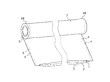
Fig. 1 is a perspective view of the rolled film
for a multiple bag of this invention, and Figs. 2 to 4
are enlarged diagrammatic view of spot-fused portions.
In the drawings, 1 refers to the first film, 2
to the second film and 3 shown in an imaginary line. to
the third film if used. 4 refers to a spot-fused portion
and the unfused portion present between one spot-fused
portion 4 and another spot-fused portion 4 is a space 5
between the spot-fused portions. The wrinkle and sag
caused when the multiple film is rolled are absorbed by
the space 5 and a multiple film rolled tightly under a
- 14 -
2200640
uniform tension is obtained. 6 refers to a paper tube
for rolling and 7 to a rolled multiple film.
The spot-fusion in this invention refers to
such a state that all films constituting the multiple
film are locally, namely, partially fused. In some
cases, the spot-fusion may be replaced by bonding with an
adhesive and the effect of this invention can be obtained
as far as the all films of the multiple film are locally
united.
Furthermore, the fusion in this invention
includes various states, for example, such a state that
the films are only fused to and fixed on one another as
shown in Fig. 2; such a state that as shown in Fig. 3, a
perforation 8 is formed at the center of the fused
portion and a fused thick portion 9 is formed around the
perforation; such a state that the center portion of the
fused portion becomes somewhat thin as shown in Fig. 4
and irregularities 10 are caused therearound; and the
like state.
The spot-fused portion means that the above
fused portion is substantially dot-like and this dot-like
fused portions exist apart from one another through
spot-fusion spaces.
The spot-fused portion is easily formed by
pressing the film by means of a heated pointed tool.
When the area of the tip is small or the pressure is
- 15 -
2200f ~0
large, a perforation 8 as shown in Fig. 3 is formed;
however, since thick portions in which the films are
mutually fused are formed therearound, the effect of this
invention is obtained.
When the area of the tip is large or the
pressure is small, no perforation is formed, but even in
this case, the center of the fused portion becomes thin
as shown in Fig. 4 and thick portions are formed
therearound to cause irregularities, whereby the effect
of this invention is achieved.
The irregularities in the spot-fused portion
has such an effect that when the film is rolled the
adjacent multiple films are entangled with each other,
and when the film is rolled as shown in Fig. 1, both ends
48 become thick, the multiple film per se in the center
portion is consequently loosely rolled, and the rolled
films are not blocked with each other, so that neither
wrinkle nor sag are generated. Therefore, the subsequent
automatic bag-making-and-packing step is smoothly carried
out.
The shape of the spot is not critical, and
include, for example, a circle shape, an oval shape, a
square shape and the like.
When the spot has, for example, a circle shape,
the size of the spot is 1 to 10 mm, preferably 2 to 5 mm
in diameter because it is necessary that a heat applied
- 16 -
2200~'~ Q
for the fusion be transferred to the whole of the
thickness of the film which can freely mutually moved.
However, this size is varied depending upon the thickness
of the film and the composition of the starting material
for the film and in general, when the film is thin or
easy to melt, a small diameter spot is sufficient.
The size of a space between the spot-fused
portions is varied depending upon how the film is easy to
slip, the number of films piled, the fusion strength and
whether other processings are applied. In general, the
size of space is 1 to 30 cm, preferably 5 to 20 cm.
Briefly, it is sufficient that such a size that even when
in the multiple film, each film is moved to change its
relative position the deviation caused thereby can be
absorbed is assured. If the above requirements are
satisfied, neither wrinkle nor sag are caused in other
portions than both-side edge portions of the rolled film.
When a group of fine scars are densely formed
in addition to providing spot-fused portions in both-side
edge portions, the effect of this invention is much more
increased.
In this invention, the scars are flaws formed
by pressing the multiple film from one side by means of a
somewhat pointed material as shown in Figs. 5A and 5B,
and these flaw are preferably such that the film projects
from the other side of the multiple film.
- 17 -
2200640
In Figs. 5A and 5B, 11 refers to the first film
and 12 to the second film. The two are merely put one on
the other, are not bonded to one another at all, and are
in such a state that they can be freely mutually moved in
other portions than the scars. 13 refers to a scar, a
concave 14 is formed by pressing the first film 11 by
means of a working tool in the arrow direction, the first
film is fitted in the concave of the second film to bond
the two films in this position. Moreover, the second
film 12 indirectly pressed projects to the opposite side
surface to form a protrusion 15. The protrusion 15 has
the action of a wedge that at least two films which can
be freely mutually moved are connected for the necessary
period of time.
Fig. 5A shows the case where the scar 13 forms
a perforation 16, and Fig. 5B shows the case where the
scar 13 does not form a perforation but merely a protru-
sion 15 in the second film 12.
In this invention, the scar 13 does not always
have a perforation and it is sufficient that the first
film is fitted in the second film. In the case of Fig.
5B, the outer surface of the second film 12 project;
however, even when the second film does not project, the
object of this invention can be achieved when the two
films are assuredly locally bonded.
In Figs. 5A and 5B, a double layer film is
- 18 -
~20U640
shown; however, even when this film has three or more
layers, the same applies.
The scar 13 is densely provided in both-side
edge portions of the multiple film.
When this multiple film is rolled, for example,
in such a way that the first film 11 becomes an inner
surface, the second film 12 becomes an outer surface. In
the side edge portion of the second film 12, there are
many scar protrusions 15, so that a roll is formed in
which the protrusions 15 of the second film 12 are fitted
in the concaves 14 of the first film 11 which is wound
thereon and contacts with the second film 12.
The thus fitted-in portions or the portions in
which the protrusions 15 are not fitted in but intimately
contacted with the surface of the first film 11 have
strong frictional resistance and tightly fix the multiple
film in both-side edge portions to prevent the winding
breakage. In addition, in the case where a bag is made
by an automatic bag-making-and-packing machine, the
fitted-in portions have such a function that the multiple
film is united during unwinding, fusing, packing and
sealing.
When the multiple film is rolled in such a way
that the second film becomes an inner surface, the
protrusions 15 of the second film are fitted in the
concaves 14 of the first film or the protrusions 15 bite
- 19 -
2200640
the first film 11, whereby the films which can be freely
mutually moved can be kept in the fixed state for the
necessary period of time.
The shape of the scar is not critical and may
be a circle shape, a triangle shape, a polygon shape, an
oval shape or the like as far as the tip is microscopi-
cally somewhat pointed. Moreover, it is not necessary
that the scars be provided in the form of a dot, and they
may be provided in the form of a horizontal line, a
vertical line or a slash as far as they are provided in
the side edge portions. In short, protrusions 15 are
formed on the first film 11, and penetrate into the
second film 12. When the third film is present, the
shape of scar is not critical as far as the protrusions
of the second film penetrate into the third film. The
group of scars provided in the side edge portions of such
a multiple film have such a function as to tentatively
bond the films which can freely mutually moved to one
another in the side edge portions.
The space between the scars is 3 to 15 mm,
preferably 7 to 15 mm.
When the film is further rolled, the
protrusions 15 in the side edge portions knock against
the film surface which contacts the protrusions, and
consequently, the thickness of the side edge portion
becomes larger, and the protrusions are entangled with
- 20 -
z2oos4~
one another to make it assured to roll the film. In the
center portion, each film of the multiple film is loosely
rolled and a play is kept between the films, and hence,
neither wrinkle nor sag is formed. Moreover, when the
roll is unwound, the outermost layer multiple film does
not stick to the subsequent layer multiple film, and
hence, the unwinding is not impeded, and a roll state is
obtained which is more suitable to the automatic bag-
making-and-packing machine.
Only spot-fused portions may be provided or
both spot-fused portions and a group of scars may be
provided together as far as they have such a function as
to unite the multiple film during unwinding the multiple
film and then carrying out bag-making, packing and seal-
ing in the automatic bag-making-and-packing machine.
When a group of scars are provided, the method
of providing the same is not critical; however, it is
preferable to press the side edge portions of the
multiple film using a rotating disk. This disk has many
protrusions on its periphery and the protrusions press
the side edge portions of the multiple film. The protru-
sions have a sectional shape of triangle. It is prefer-
able to scatter or arrange zigzag dot-like protrusions
pointed like- a drill which constitute scars. Also, it is
possible to arrange and use slender ridge-like protru-
sions. In this case, the ridge -like protrusions have
- 21 -
22006~~
preferably a sectional shape of triangle.
The length of the protrusion and the pressing
pressure are varied depending upon the kind of the
multiple film, and are such that when pressed from one
surface of the multiple film the protrusion appears on
the other surface.
Even if the protrusions do not appear on said
other surface, it is sufficient that the layers of the
multiple film are entangled with one another and the
layers of the multiple film are tentatively bonded by a
synergistic effect between the protrusions and the spot-
fused portions to such an extent that they are not
separated from one another during the unwinding of the
film and subsequent carrying out of bag-making, packing
and sealing in an automatic bag-making-and-packing
machine.
The spot-fused portions may be provided
together with the group of scars or in separate portions.
It is also possible to use the first film
having fusible layers on both surfaces and use a double
layer film in which the layers are in the mutual blocking
stage together with a second film and a third film.
The blocking state does not mean the state in
which the contacting fusible films have been completely
united with an adhesive or by fusion, but the state in
which the contacting films are weakly bonded by the
- 22 -
mutual tackiness, for example, self-tackiness, tentative
tackiness due to plasticizer, or the like, and can be
easily separated by a light force. Briefly, the films
are in a somewhat sticky state.
An explanation is made below of the process for
producing a packed multiple bag of this invention and the
apparatus of this invention to be used in the production
process referring to the drawings.
The process for producing a packed multiple bag
of this invention comprises a step of forming a multiple
film by putting at least two sheets of film one on
another, a step of discontinuously providing spot-fused
portions along both-side edge portions of the multiple
film, by which spot-fused portions the at least two
sheets of film are partially united, a step of fusing the
multiple film in the longitudinal direction to form a
cylindrical film, a step of packing contents in the
cylindrical film and fusing the cylindrical film in the
transverse direction, and a step of cutting the fused
portion in the transverse direction.
The apparatus of this invention for producing
the packed multiple bag comprises a film-feeding means
having at least two film-feeding rolls, a means for
fusing in the longitudinal direction, a means for packing
contents, a means for fusing in the transverse direction,
a means for cutting the fused portion in the transverse
- 23 -
2200640
direction, and a spot-fusing means for intermittently
fusing at least two films fed from the said at least two
film-feeding rolls in the state that the films are put
one on another, along their both-side edge portions, the
spot-fusing means being provided between the film-feeding
means and the means for fusing in the longitudinal
direction.
Fig. 6 is an outlined view of the apparatus of
this invention for producing the packed multiple bag.
The film-feeding means 17 is provided with at least two
film-feeding rolls 18. In Fig. 6, the film-feeding means
is provided with three film-feeding rolls 18a, 18b and
18c. It is preferable for the film-feeding means 17 to
have a means for controlling the tension of the film to
be fed.
Alternatively, it is possible to provide a
film-feeding means in which at least two films are rolled
together on one film-feeding roll, in place of the at
least two film-feeding rolls. However, when at least two
films are rolled on one film-feeding roll, winding
breakage is apt to be caused, and hence, it is more
preferable to provide a group of fine protrusions which
reach from one film to another film, in both-side edge
portions to entangle the films, thereby preventing
winding breakage.
When the group of fine protrusions are
- 24 -
provided, the method of providing the same is not
critical, and, for example, the at least two sheets of
film put one on another are pressed using a rotating
disk. This disk has a group of many fine protrusions on
its periphery.
The length of the protrusion and the pressing
pressure are varied depending upon the kinds of at least
two films to be processed and are such that when the
protrusions are pressed from one film surface, they
appear on the other film surface. Alternatively, even if
the protrusions do not appear on the other film surface,
it is sufficient that the at least two films are
entangled, tentatively bonded and stably rolled without
causing winding breakage.
As the fusing means 19, it is possible to use a
pair of back-up roll 20 and hot pin roll 21 which are
rotated in opposite directions at the same speed in
contact with each other. The hot pin roll 21 has many
heated pins (22 in Fig. 7) projecting from the outer
periphery, and the heated pins 22 enable the at least two
films fed from the film-feeding rolls 18a, 18b and 18c in
Fig. 6 to be locally melt-united. The back-up roll 20
has coated thereon a releasable material resistant to the
heat and the_pressing pressure during the processing.
Only one of the back-up roll 20 and the hot pin
roll 21 may be driven or both of them may be driven.
- 25 -
2~oos4o
Fig. 7 is a sectional view of the hot pin roll
21 and Fig. 8 is a sectional view of the hot pin roll of
Fig. 7 at the III-III line. The hot pin roll 21 is a
disk which is rotated with the rotation of the rotary
shaft and heaters 28 are embedded near the periphery of
the disk to heat the hot pins 22. 29 refers to a keyway
for assuredly associating the hot pin roll with the
rotary shaft 27.
The hot pin roll 21 may be fitted with the hot
pins 22 in a line or plural lines or zigzag on the
peripheral surface of the hot pin roll 21. The pitch of
the intermittent fusions is varied depending upon the
pitch of the hot pins planted and can be determined
appropriately depending upon the kind of film, the kind
of bag to be produced and the contents to be packed.
Also, the heating temperature of the hot pins 22 are
varied appropriately depending upon the kind and
thickness of film to be used, the pressing pressure, the
packing speed and the like.
In general, as the hot pins, there are planted
metal bars having a diameter of 2 to 10 mm and a projec-
tion length of 1 to 10 mm and having a pointed tip 30.
The specific shapes of the hot pin are such that the
diameter is 6 mm, the length of the projected portion is
3.5 mm and the tip 30 has a half circle shape as shown in
Fig. 9A or such that the diameter is 6 mm, the length of
- 26 -
220064
the projected portion is 3.5 mm and the diameter of the
tip 30 is 3 mm and the point angle A of the tip 30 is 30'
as shown in Fig. 9B.
Another fusing means 19 consists of, as shown
in Fig. 10, the first plate 40 having a built-in heater
28 for heating the projected hot pins 22 and the second
plate 41 placed in parallel thereto.
At least two films fed from the film-feeding
rolls 18a, 18b and 18c are intermittently moved between
the first plate 40 and the second plate 41 which are
intermittently opened and closed so as to meet the timing
of the opening and closing of the plates. That is, when
the first plate 40 and the second plate 41 are closed and
the films are discontinuously fused with the hot pins,
the films are stopped, and when the fusion is completed
and the plates are opened, the films are sent by the
given distance.
By repeating the above intermittent operation,
the at least two films are discontinuously fused and
consequently spot-fused portions become scattered on the
film surface.
The opening and closing of the plates may be
carried out by moving the first plate 40 and the second
plate 41; however, it is preferable that the second plate
4l is allowed to rest and the first plate 40 is moved to
carry out the opening and closing movement. The number
- 27 -
220064 (i
of the hot pins 22 may be one; however, it is preferable
that plural hot pins project. They may be arranged in a
line or plural lines or arranged zigzag, and the arrange-
ment is not critical. The pitch of the discontinuous, or
scattered fusions can be varied appropriately depending
upon the pitch of the hot pins planted, the kind of film,
the kind of bag to be produced and the contents to be
packed.
The surface of the second plate 41 contacting
the first plate 40 is coated with a releasable material
resistant to the heat during the intermittent fusion
processing and to the pressing pressure. In the fusing
means 19 shown in Fig. 10, the hot pins shown in Figs. 9A
and 9B are also preferably used.
Moreover, there is a case where the hot pins 22
are not projected from either the first plate 40 or the
second plate 41. In this case, the plates are short as
shown in Fig. 11, and when the first plate 40 is
contacted with the second plate 41, there is formed a
fused portion having the same length as the plate in the
longitudinal direction.
In this invention, it is necessary that unfused
portions through which air present between the at least
two films can be escaped be present and simultaneously it
is necessary that the unfused portions are present at
such a space that neither wrinkle nor sag are not
- 28 -
~2~~64~
generated between the at least two films. Accordingly,
it is important, though the shapes of the hot pin and the
plate do not become a problem, that the place and length
be kept so that the wrinkle of the film can be absorbed
and it is also important that the place and length be
such that the automatic bag-making-and-packing machine
can work without any troubles during bag-making.
In Fig. 6, 23 is an accumulator, and a dancer
roll 25 which can be moved upwardly and downwardly is
provided between a pair of fixing rolls 24. In Fig. 6, a
pair of fixing rolls and a dancer roll are illustrated;
however, plural pairs of fixing rolls may be used. From
the fusing means 19, an intermittently fused multiple
film is continuously fed; however, in the automatic bag-
making-and-packing machine 26, there is a time at which
the flow of the film is stopped every production of one
bag, and the demand of the film is intermittent. The
dancer roll 25 is moved downwardly when the demand of the
film by the automatic bag-making-and-packing machine 26
is stopped, to store the film and when the automatic)
bag-making-and-packing machine 26 uses the film in a
large amount, the dancer roll 25 is moved upwardly to
feed a large amount of the film.
By providing the dancer roll, in the hot pin
means shown in Figs. 7 and 8, the film is continuously
fed from the film-feeding roll without the flow of the
- 29 -
220064 tl
film being stopped, so that the feed of a heat from the
heated pin to the film is stabilized, whereby the uniform
intermittent fusion is made possible.
On the other hand, in the fusing means shown in
Figs. 10 and 11, the fusion is effected intermittently,
but the preferable contacting space between the first
plate and the second plate is not consistent with the
preferable bag-making space of the automatic bag-making-
and-packing machine in many cases. Accordingly, by
providing the dancer roll, it is made possible to operate
both the fusing means and the automatic bag-making-and-
packing machine at the best spaces.
Fig. 12 is a perspective view of an example of
an automatic bag-making-and-packing machine. 26 is a
known automatic bag-making-and-packing machine, and this
is generally of a vertical type or a horizontal type,
which include various types such as three-way sealed
type, four-way sealed type, pillow type, gusset type and
the like. However, the fusing means in this invention
may be installed before the vertical fusing means for
fusing the film in the longitudinal direction.
In Fig. 12, a vertical pillow type automatic
bag-making-and-packing machine is shown as an example;
however, this invention is applicable to any of automatic
bag-making-and-packing machines of known types such as a
vertical pillow type, a horizontal pillow type, a
- 30 -
2zoos~ o
vertical three-way sealing type, a horizontal three-way
sealing type and other types.
31 is a sailor, the top of which is provided
with a hopper which is a part of the content-packing
means. In the case of a horizontal type automatic bag-
making-and-packing machine, a different type content-
packing means is used. The film 32 fed is wounded round
the sailor 31, the back surfaces of both side edges are
contacted with each other, the film is sent downward in
this state, the back surfaces are bonded by means of a
heated vertical sealer 33 to complete the vertical
sealing. At this time a tap, not shown in Fig. 12, may
be attached to the film between the vertical sealer 33
and a horizontal sealer 36. 34 is a feed roller and 35
is an auxiliary belt. The horizontal sealer 36 press-
fuses the vertically sealed film in the form of a
cylinder by means of a pair of hot sealing bar in the
direction perpendicular to the cylindrical film to form a
bag bottom. Thereafter, a given amount of the contents
is packed therein from the top of the sailor 31 and then
the bag is moved down by the length of one bag. At this
time, the bag is horizontally sealed by means of a
horizontal sealer provided with a horizontal fused
portion cutter 37 in the center portion of the sealed
portion, whereby the opening of the preceding bag is
sealed and simultaneously the bottom of the succeeding
- 31 -
2200640
bag is formed. 38 is a finished pillow type sealed
packed bag. The sealed packed bag 38 produced is
conveyed to the given place by means of a belt conveyer
39.
Fig. 13 is an outlined view of an apparatus for
producing a rolled film. From film rolls 42a and 42b,
two sheets of film 43 are put one on the other on a
roller, and the resulting assembly is fed to between a
scar-imparting means 44 and its back-up roll 46b. A
double layer film having scars imparted on its surface is
fed to between a spot-fusing means 45 and its back-up
roll 46a. The films locally united by the spot-fusion
are rolled in the form of a multiple film roll 47.
Example 1
To both sides of a biaxially oriented nylon
film which had been coated with polyvinylidene chloride
(referred to hereinafter as KON#15) were laminated a low
density polyethylene film (referred to hereinafter as PE)
and a linear, low-density polyethylene film (referred to
hereinafter as LL) by an extrusion coating method to
produce the first film having a width of 1 m which was a
laminated film composed of LL15/PE15/KON#15/PE20/LL30
(hereinafter, suffixes refer to thicknesses in um and "#"
means a film). The surfaces of both terminal LL's were
roughened using a textured roll as a cooling roll in the
- 32 -
220060
extrusion step.
Subsequently, using the apparatus shown in Fig.
6, the LL30 side of the first film was put on a second
film of LL#75 having a width of 1 m, and both-side edge
portions of the resulting assembly were spot-fused to
form dot-like spot-fused portions 4 in the form of a
circle having a diameter of 3 mm arranged in a line at
spot-fusion spaces of 10 cm. This assembly was rolled on
a paper tube having a nominal diameter of 3 inches, a
paper thickness of 12 mm and a length of 1.1 m so that
the second film LL#75 became inside to prepare five rolls
each having a length of 300 m and five rolls each having
a length of 600 m. By this method, there were obtained
winding-breakage-free multiple film rolls in which both-
side edge portions were somewhat swollen.
The spot-fusing processing was carried out by
passing the first film and the second film in the state
that the two are put on each other through between a disk
of 10 cm in diameter having circular protrusions of 3 mm
in diameter on its periphery heated to 270°C and a
silicone rubber-lined back-up roll.
Corrugated paper having a thickness of 2 cm, an
inner diameter of 3 inches and an outer diameter
corresponding to the diameter of the film roll obtained
was applied to both sides of the rolled film and the
resulting assembly was packaged with a polyethylene film,
- 33 -
zz~of4o
and subsequently, a steel tube having a nominal diameter
of 32A and a length of 1.3 m was inserted into the paper
tube. Both ends of the steel tube were placed on a rack
to allow the roll to hang so that the weight of the roll
per se was not applied to the roll. This rack was placed
on a truck and transported about 500 km to find that none
of the five 300-m rolls caused winding breakage, but 4 of
the five 600-m rolls caused winding breakage owing to the
slippage of film. The winding breakage was not owing to
the film slippage between the first film and the second
film but the film slippage between the multiple films.
Using a vertical pillow type packing machine,
the 300-m roll film and the 600-m roll film which did not
cause winding breakage were formed into a pillow type bag
so that the second film LL#~5 became the inside of bag
and simultaneously 10 kg of water was packed in the
resulting bag. In either case of the 300-m roll or the
600-m roll, the first film and the second film were able
to be smoothly subjected to continuous operation without
causing slippage nor wrinkle.
One packed bag was placed in one corrugated
box, and nine boxes thereof were arranged (3 x 3, single
pile) and vibrated at each temperature of 29°C and 3°C
for 40 minutes in the vertical direction and for 20
minutes in the horizontal direction using a vibration
testing machine manufactured by IMV wile continuously
- 34 -
~zoos4o
changing the frequency between 5 Hz and 50 Hz and keeping
the vibration acceleration speed at 0.75 G. This
vibration test was repeated twice on each of the boxes at
each temperature of 29'C and 3°C. In total, 18 bags were
tested at each temperature. In any of the bags, no
pinhole was formed in either of the first and second
films and water did not leak out of the films.
Example 2
The same first and second films as in Example 1
were put one on the other in the same manner as in
Example 1. Moreover, in the present Example, a group of
dot-like scars were arranged zigzag in 7 lines at a space
of 3.5 mm on the outer surface of the spot-fused portion.
In the processing, the multiple film was pressed on the
outside of the spot-fusion in the side edge portion by
means of a processing tool in which triangular protru-
sions were arranged on the periphery of a disk having a
width of 3.5 mm zigzag in 7 lines in the thickness
direction of the disk and zigzag at a pitch of 1.5 mm in
the peripheral direction. This multiple film was rolled
in the same manner as in Example 1 to form five 600-m
rolls and the rolls were packaged in the same manner as
in Example 1, after which the five packaged rolls were
transported about 500 km by truck. None of the rolls
caused winding breakage.
- 35 -
22006~u
Reference Example 1
The same first and second films as in Example 1
were put one on the other and dot-like scars were
imparted in both-side edge portions in the same manner as
in Example 2. This multiple film was rolled on a paper
tube having a nominal diameter of 3 inches, upon which
winding breakage was easily caused owing to the slippage
of film when about 200 m of the film was rolled. In many
cases, the winding breakage was mainly caused owing to
film slippage between the first and second films and also
caused owing to film slippage between the multiple films.
Comparative Example 1
For comparison, to the same first film as in
Example 1 was laminated the second film LL#~5 by a dry
lamination method, whereby a film of LL15/PE15/KON#15/
PE20/LL30//LL#~5 was prepared.
When the film was subjected to the same test as
in Example 1, nine of 50 bags were broken.
Example 3
The second film 2 of LL#50-LL#50 was put on the
LL30 surface of the first film 1 consisting of LL15/PE15/
KON#15/PE20/LL30 obtained in Example 1 in the same manner
as in Example 1. Moreover, in the present Example, a
group of dot-like scars was arranged zigzag in a width of
- 36 -
2200640
3.5 mm in 7 lines on the outside of the spot-fused
portions. In the processing, the outside of the spot-
fused portions in the side edge portion of the multiple
film was pressed by means of a processing tool in which
triangular protrusions were arranged zigzag in 7 lines on
the peripheral surface of a rotary disk having a thick-
ness of 3.5 mm.
The LL#50-LL#50 film was a linear low-density
polyethylene film having a total thickness of 100 um in
which the inner surface was mutually blocked, namely,
sticky, obtained by subjecting a linear, low-density
polyethylene film having a thickness of 50 um to an
inflation molding method to form a film having a thick-
ness of 50 um and a perimeter of about 2 m, drawing off
the film by means of a drawing-off nip roll and simul-
taneously folding the tube-shaped film, applying a
pressure thereto, thereafter cutting off the folding
portion of both ends of the film by means of a slitter.
This piled film was rolled on a paper tube
having a nominal diameter of 3 inches and a paper
thickness of 12 mm to obtain a 500-m length roll quite
free from wrinkle having a diameter of 360 mm.
In case spot-fusions and a group of fine scars
were densely provided in the side edge portions of the
multiple film, winding breakage was not caused and
winding wrinkle was not generated when the film was
- 37 -
CA 02200640 2000-02-O1
rolled on the paper tube. Accordingly, when the film was
subjected to an automatic bag-making-and-packing machine,
such an effect that the roll was more smoothly unwound
was recognized.
This application is based on Japanese Patent
Application No. 08-091832 filed March 22, 1996, Japanese
Patent Application No. 08-214033 filed July 26, 1996 and
Japanese Patent Application No. 08-035757 filed January
31, 1996.
- 38 -