Language selection

Search

Patent 2200674 Summary

Third-party information liability

Some of the information on this Web page has been provided by external sources. The Government of Canada is not responsible for the accuracy, reliability or currency of the information supplied by external sources. Users wishing to rely upon this information should consult directly with the source of the information. Content provided by external sources is not subject to official languages, privacy and accessibility requirements.

Claims and Abstract availability

Any discrepancies in the text and image of the Claims and Abstract are due to differing posting times. Text of the Claims and Abstract are posted:

  • At the time the application is open to public inspection;
  • At the time of issue of the patent (grant).
(12) Patent: (11) CA 2200674
(54) English Title: COATED RIVET AND DEFORMATION THEREOF
(54) French Title: RIVET ENDUIT ET DEFORMATION DE CE RIVET
Status: Deemed expired
Bibliographic Data
(51) International Patent Classification (IPC):
  • F16B 19/04 (2006.01)
  • F16B 19/06 (2006.01)
(72) Inventors :
  • BRILES, FRANKLIN S. (United States of America)
  • AURENTZ, JOHN A. (United States of America)
(73) Owners :
  • ALLFAST FASTENING SYSTEMS, INC. (United States of America)
(71) Applicants :
  • BRILES, FRANKLIN S. (United States of America)
(74) Agent: GOWLING WLG (CANADA) LLP
(74) Associate agent:
(45) Issued: 2001-05-01
(22) Filed Date: 1997-03-21
(41) Open to Public Inspection: 1997-11-24
Examination requested: 1997-12-11
Availability of licence: N/A
(25) Language of filing: English

Patent Cooperation Treaty (PCT): No

(30) Application Priority Data:
Application No. Country/Territory Date
08/653,458 United States of America 1996-05-24

Abstracts

English Abstract


The method of connecting two workpiece sheets
using a rivet, one sheet have a bore, and a counterbore
which is frusto-conical and tapers forwardly between a
side of the one sheet and the bore, and toward the bore
that includes providing a metallic rivet having an
axially extending shank defining an axis; providing the
rivet with a head having an end face and a forwardly
tapered frusto-conical section located forwardly of the
end face; installing the shank in the bore and the head
in the counterbore so that the periphery of the head end
face is substantially flush with the work surface, the
end face formed to provide a ring-shaped dome protruding
axially in a rearward direction, the dome located to
extend about the axis in substantially axial alignment
with the outer surface of the shank; the rivet head
provided with a peripheral side wall spaced radially
from a side wall defined by the workpiece counterbore,
and the space between the side walls having a volume A;
the dome provided with a metallic volume B; and wherein
volume B exceeds volume A, such that when the dome is
flattened during rivet deformation, the rivet head side
wall is radially expanded into volume A and pushes
outwardly against the workpiece counterbore side wall to
deform the latter radially outwardly. The rivet may be
coated to provide barrier material between the rivet
side wall and the workpiece counterbore side wall to
fill interstices between the side wall after radially
outward deforming of the workpiece counterbore side
wall. Upon completion of the installation, to provide


retained clamp-up of the sheets and protection of the
connection from corrosion.


French Abstract

Méthode de raccordement de deux feuilles à l'aide d'un rivet, une feuille ayant un trou et un lamage qui est frusto-conique et de section réduite vers l'avant entre le côté d'une feuille et l'alésage, et vers l'alésage, qui comprend un rivet métallique avec tige se prolongeant dans l'axe et définissant un axe; le rivet comporte une tête ayant une face d'extrémité et une section frusto-conique effilée vers l'avant située en avant de la face d'extrémité; la tige est installée dans l'alésage et de la tête dans le lamage de sorte que la périphérie de la face d'extrémité de la tête arrive sensiblement d'affleurement par rapport à la surface de travail, la face d'extrémité est formée pour constituer un dôme en forme d'anneau dépassant axialement vers l'arrière, le dôme étant placé pour se déplacer autour de l'axe dans un alignement sensiblement axial par rapport à la surface extérieure de la tige. La tête de rivet comprend une paroi latérale périphérique espacée radialement d'une autre paroi définie par le lamage de la pièce de travail, et l'espace entre les parois correspondant à un volume A; le dôme correspondant à un volume B et le volume B est supérieur à un volume A de sorte que lorsque le dôme est aplati durant la déformation du rivet, la paroi latérale de la tête de rivet prend de l'expansion radialement pour former le volume A et pousse vers l'extérieur contre la paroi du lamage de la pièce de travail pour déformer cette dernière radialement, vers l'extérieur. Le rivet peut être enduit pour créer une barrière entre la paroi du rivet et la paroi du lamage de la pièce de travail. Une fois l'installation terminée, les deux feuilles sont assemblées et la connexion est protégée contre la corrosion.

Claims

Note: Claims are shown in the official language in which they were submitted.


I CLAIM:
1. The method of connecting two workpiece sheets using a rivet, one
sheet having a work surface, a bore, and a counterbore, which is frusto-
conical and
tapers forwardly between a side of the one sheet and the bore, and toward the
bore,
the other sheet having a bore, the sheets stacked to provide upper and lower
sheets
with the bores therein coaxially aligned, the steps that include:
a) providing a metallic rivet having an axially extending shank defining
an axis,
b) providing the undeformed rivet with a head having an end face, a
cylindrical section located forwardly of the end face, and a forwardly
tapered frusto-conical section located forwardly of said cylindrical
section,
c) installing said shank in said bore and said head in the counterbore so
that the periphery of said head end face is substantially flush with the
work surface, the end face formed to provide a ring-shaped dome
protruding axially in a rearward direction, above the level of the one
sheet work surface, said dome located to extend about said axis in
substantially axial alignment with the outer surface of the shank, and
deforming the rivet to connect the two workpiece sheets together, said
deforming including flattening of said ring-shaped dome,
d) the rivet head provided with a peripheral side wall spaced radially
from an inner wall defined by the workpiece counterbore, and the
space between said inner wall and said side wall having a volume A,
e) said ring-shaped dome provided with a metallic volume B,
f) and wherein volume B exceeds volume A, such that when the dome is
flattened during rivet deformation, said rivet head side wall is radially
expanded into volume A and pushes outwardly against said workpiece
counterbore inner wall to deform the latter radially outwardly,
g) and coating the rivet to provide barrier material on said ring-shaped
dome and between said rivet side wall and said workpiece counterbore,
-22-


such that, upon deformation of the rivet, barrier material fills metallic
interstices between said side wall and inner wall and penetrates into
metallic interstices at the surface of the flattened dome.
2. The method of claim 1 wherein said barrier material includes a
corrosion inhibiting agent.
3. The method of claim 2 wherein said corrosion inhibiting agent consists
essentially of an aluminized, pigmented coating.
4. The method of claim 2 wherein dome flattening is carried out so that
shear load bearing areas are formed around the expanded rivet head to have
thickness
which remains at least 40 % of the thickness of the workpiece sheet in which
the head
is located.
5. The method of claim 1 wherein said barrier material includes a sealant.
6. The method of claim 5 wherein said sealant consists essentially of a
flexible polysulfide coating.
7. The method of claim 5 wherein said sealant is non-metallic and
deformable.
8. The method of claim 1 wherein
h) the ratio B/A being within the range 1.20:1 to 70:1,
i) the head end face formed to define a recess bounded by said
ring-shaped dome, and
j) dome flattening is carried out to provide shear load bearing areas
around the expanded rivet head to have thickness which remains at
least 40 % of the thickness of the workpiece sheet in which the head is
located.
9. The method of claim 8 wherein A and B have one of the follow two
relationships:
x1 A is within the range 0.0000120 cubic inches and 0.000190 cubic
inches; and B is provided to be within the range 0.0000125 cubic
inches and 0.00090 cubic inches,
x2 A is within the range 0.0000013 cubic inches and 0.000013 cubic
-23-


inches; and wherein B is within the range 0.000029 cubic inches and
0.00088 cubic inches.
10. The method of claim 1 wherein the dome is flattened during rivet
deformation so that shear load bearing areas are formed around the expanded
rivet
head to have thickness which remains at least 40 % of the thickness of the
workpiece
in which the head is located.
11. The method of claim 1 wherein A is provided to be within the range
0.0000120 cubic inches and 0.000190 cubic inches; and B is provided to be
within
the range 0.0000125 cubic inches and 0.00090 cubic inches.
12. The method of claim 1 including forming the dome to have an annular
crest portion in substantial axial alignment with said shank outer surface,
and the
dome having radially outer extent which defines only about half of the dome
being
located in axially spaced relation to a forward taper defined by said
forwardly tapered
frusto-conical section, said dome crest portion being rearwardly convex.
13. The method of claim 12 wherein the head end face is formed to have
a concave central recess radially inwardly of said crest portion.
14. The method of claim 12 wherein both the rivet and workpiece sheets
are metallic, the rivet metal being softer than the workpiece sheets.
15. The method of claim 1 wherein the rivet is metallic and consists of one
of the following:
i) aluminum
ii) aluminum alloy
iii) titanium
iv) titanium alloy
v) CRES alloy.
16. The method of claim 14 wherein said one sheet metallic inner wall is
deformed radially outwardly during said rivet deformation.
17. The method of claim 1 wherein the head maximum diameter is within
the range 0.121 to 0.521 inches.
18. The method of claim 1 wherein said head side wall has an axial length
-24-


of about 0.012 to 0.042 inches.
19. The method of claim 1 including coating said barrier material onto the
rivet side wall prior to said rivet deformation.
20. The method of claim 19 wherein said barrier material has coating
thickness between 0.0002 and 0.006 inches.
21. The method of claim 19 wherein said deformation causes forcing of the
barrier material against said counterbore inner wall.
22. The method of claim 21 including also coating said barrier material
onto said forwardly tapered frusto-conical section, said flattening of the
dome causing
said barrier material on said frusto-conical section to penetrate into
metallic interstices
of said one sheet, frusto-conical counterbore.
23. The method of claim 1 wherein said barrier material also extends
adjacent said counterbore which tapers forwardly between a side of the one
sheet and
the bore.
24. The method of claim 23 wherein said barrier material includes a
corrosion inhibiting agent.
25. The method of claim 24 wherein said corrosion inhibiting agent
consists essentially of an aluminized, pigmented coating.
26. The method of claim 23 wherein said barrier material includes a
sealant.
27. The method of claim 26 wherein said sealant consists essentially of a
flexible polysulfide coating.
28. The method of claim 1 wherein said barrier material consists of at least
one of the following:
i) aluminized metallic particles
ii) epoxide resin.
29. The method of claim 28 wherein said barrier material has thickness
variation of about 0.0002 inches to 0.006 inches.
30. The method of connecting two workpiece sheets using a rivet, one
sheet having a work surface and bore, and a counterbore which is frusto-
conical and
-25-


tapers forwardly between a side of the one sheet and the bore, and toward the
bore,
the other sheet having a bore, the sheets stacked to provide upper and lower
sheets
with the bores therein coaxially aligned, the steps that include:
a) providing a metallic rivet having an axially extending shank defining
an axis,
b) providing the undeformed rivet with a head having an end face, a
cylindrical section located forwardly of the end face, and a forwardly
tapered frusto-conical section located forwardly of said cylindrical
section,
c) installing said shank in said bore and said head in the counterbore so
that the periphery of said head end face is substantially flush with the
work surface, the end face formed to provide a ring-shaped dome
protruding axially in a rearward direction, above the level of the one
sheet work surface, said dome located to extend about said axis in
substantially axial alignment with the outer surface of the shank, and
deforming the rivet to connect the two workpiece sheets together, said
deforming including flattening of said ring-shaped dome, the rivet head
provided with a peripheral side wall spaced radially from an inner wall
defined by the workpiece counterbore, and the space between said side
walls having a volume A,
e) said ring-shape dome provided with a metallic volume B,
f) and wherein volume B exceeds volume A, such that when the dome is
flattened during rivet deformation, said rivet head sidewall is radially
expanded into volume A and pushes outwardly against said workpiece
counterbore inner wall to deform the latter radially outwardly,
g) and coating the rivet to provide barrier material on said ring-shaped
dome and between said rivet side wall and said workpiece counterbore
such that upon deformation of the rivet, barrier material fills metallic
interstices between said side wall and inner wall and penetrates into
metallic interstices at the surface of the flattened dome,
-26-


h) said deformation of the rivet also causing formation of a rivet buck-tail
adjacent the other sheet.
31. The method of claim 30 wherein said dome flattening causes said
barrier material to extend into overlapping relation with edges defined by
said head
side wall and by the workpiece counterbore side wall.
32. In the method of clamping together two workpiece sheets using a rivet,
one sheet having a work surface, a bore, and a counterbore, which is frusto-
conical
and tapers forwardly between a side of the one sheet and the bore, and toward
the
bore, the other sheet having a bore, the sheets stacked to provide upper and
lower
sheets with the bores therein coaxially aligned, the lower sheet having an
outer lower
surface, the steps that include
a) providing a metallic rivet having an axially extending shank defining
an axis, the rivet metal consisting essentially of fine-grained, ductile,
aluminum alloy,
b) providing the rivet with a head having an end face and a forwardly
tapered frusto-conical section located forwardly of the end face,
c) installing said shank in said bore, with part of said head in the
counterbore, so that the periphery of said head end face is substantially
flush with the work surface, the end face formed to provide a
ring-shaped dome protruding axially in an upward direction, said dome
located to extend about said axis in substantially axial alignment with
the outer surface of the shank, the ring-shaped dome also forming a
central recess,
d) the rivet head provided with a peripheral side wall spaced radially
from an inner wall defined by the workpiece counterbore, the rivet
shank having an end terminal,
e) applying force to said ring-shaped dome and to said end terminal to
cause the shank proximate said end terminal to expand and engage the
lower surface of the lower sheet, and simultaneously to cause said
ring-shaped dome to flatten, and to cause fine-grain shank aluminum
-27-


alloy metal to backflow upwardly to effect flow of metal upwardly and
centrally to said recess,
f) said force application being continued to cause said expanding lower
terminal to form a buck-tail adjacent the lower sheet outer surface
exerting clamping force against that outer surface, and to produce a
flattened top surface at the rivet head, whereby the two sheets are held
in forcibly clamped-up condition between said head and said buck-tail,
after formation is completed,
g) and providing protective barrier on said ring-shaped dome and material
between said rivet side wall and said workpiece counterbore, and such
that upon deformation of the rivet, barrier material fills interstices
between said side wall and said inner wall and penetrates into
interstices at the surface of the flattened dome.
33. The method of claim 32 wherein said flattened top surface of the head
is deformed to lie between 0 and 0.006 inches above the upper surface of the
upper
sheet.
34. The method of claim 33 wherein fine-grain shank metal is caused to
flow upwardly to fill said recess as said ring-shaped dome is flattened and
said
buck-tail is formed by force application, said rivet metal also characterized
by high
elongation.
35. The method of claim 32 wherein fine-grain shank metal is caused to
flow upwardly to fill said recess as said ring-shaped dome is flattened and
said
buck-tail is formed by force application.
36. The method of claim 32 wherein said rivet metal has a fine-grain size
between 5 and 9, where grain size is determined by ASTM E:112.
37. The method of claim 32 including providing said sheets to consist
essentially of metal selected from the group aluminum, titanium, stainless
alloys, and
combinations thereof.
38. The method of claim 32 including maintaining a portion of said ring-shaped

dome during completed flattening thereof above the level of said upper sheet
-28-


upper surface, and causing said barrier material to overlap edges defined by
the rivet
head side wall and the workpiece counterbore inner wall.
39. The method of claim 32 wherein rivet metal is deformed upwardly
within the shank below said counterbore, and toward said head recess, to
expand the
rivet and fill the recess, as the buck tail is formed.
40. In the method of clamping together two workpiece sheets using a rivet,
one sheet having a work surface, and bore, and a counterbore, which is frusto-
conical
and tapers forwardly between a side of the one sheet and the bore, and toward
the
bore, the other sheet having a bore, the sheets stacked to provide upper and
lower
sheets, with the bores therein coaxially aligned, the steps that include:
a) providing a metallic rivet having an axially extending shank defining
an axis, the rivet metal consisting essentially of fine-grained, ductile,
aluminum alloy,
b) providing the rivet with a head having an end face defining a
ring-shaped dome and a forwardly tapered frusto-conical section located
forwardly of the end face,
c) installing said shank in said bore, with part of said head in the
counterbore, so that the periphery of said head end face projects above
the work surface, the end face formed to provide a ring-shaped dome
protruding axially in an upward direction, said dome located to extend
about said axis in substantially axial alignment with the outer surface
of the shank, the ring-shaped dome forming a central recess,
d) the rivet head provided with a peripheral side wall spaced radially
from a side wall defined by the workpiece counterbore, the rivet shank
having an end terminal,
e) applying force to said ring-shaped dome and to said end terminal to
cause the shank proximate said end terminal to expand an engage the
exposed outer surface of the lower sheet, and simultaneously to cause
said ring-shaped dome to flatten, and to cause fine-grain shank
aluminum alloy metal to backflow upwardly to effect flow of metal
-29-


upwardly and centrally to said recess,
f) said force application being continued to cause said expanding end
terminal to form a buck-tail adjacent the lower sheet outer surface
exerting clamping force against the outer surface, and to produce a
flattened top surface of the rivet head, with said top surface lowered
toward but spaced above the upper surface level of the upper sheet,
whereby the two sheets are held in forcibly clamped-up condition
between said head and said buck-tail, after formation is completed,
g) said rivet metal having a fine-grain size between 5 and 9, where grain
size is determined by ASTM E:112,
h) said force application continued to cause the formed buck-tail to have
a diameter of at least 1.4 times the initial undeformed diameter of the
rivet shank, and whereby the fine grain of the rivet head and buck-tail
metal allow deformation of the head and buck-tail so as to substantially
eliminate spring back during clamp up,
i) said rivet metal having a % elongation value of at least 12 as measured
during tensile testing to failure of a specimen of said rivet metal.
41. The method of claim 40 wherein said flattened top surface of the head
is deformed to lie between 0 and 0.006 inches above the upper surface of the
upper
sheet.
42. The method of claim 41 wherein fine-grain shank metal is caused to
flow upwardly to fill said recess as said ring-shaped dome is flattened and
said
buck-tail is formed by force application, and shank metal is also caused to
expand and grip
walls defined by sheet bores receiving the shank.
43. The method of claim 40 wherein fine-grain shank metal is caused to
flow upwardly to fill said recess as said ring-shaped dome is flattened to lie
above the
upper surface of the upper sheet and said buck-tail is formed by force
application.
44. The method of claim 40 including providing said sheets to consist
essentially of metal selected from the group aluminum, titanium, stainless
alloys, and
combinations thereof.
-30-


45. The method of claim 40 including maintaining said ring-shaped dome
during completed flattening thereof above the level of said upper sheet upper
surface.
46. The method of claim 40 wherein rivet metal is deformed upwardly
within the shank below said counterbore, and toward said central recess, to
expand
the rivet and fill the central recess, as the buck-tail is formed.
47. The method of claim 40 wherein rivet metal is filled into the central
recess to lock the rivet head against radially inward contraction, whereby
said
clamped-up condition is maintained.
48. The method of claim 40 wherein said aluminum alloy is selected from
the group that includes:
2017-T4

2024-T4

2117-T4

2219-T62

7050-T73

7050-T715.

49. The method of claim 40 wherein the rivet is formed from aluminum

alloy wire selected form the following table group, said selected wire having
grain


size and physical characteristic as recited in the following table:


Shear Grain Size

Elongation Strength Maximum

Alloy & Diameter in in 2 Inches, Min. Max. ASTM


Temper Inches Minimum % Ksi Ksi E:112

2017-T4 0.92 thru 14 35 41 7

0.565

2024-T4 0.92 thru 13 37 N/A 6

0.565

2117-T4 0.92 thru 18 26 N/A 5


0.565
2219-T62 0.92 thru 12 30 N/A 5

0.565

7050-T73 0.92 thru 14 41 46 5

0.565

7050-T715 0.92 thru 15 35 51 5

0.565

-31-


50. The method of claim 40 including determining wherein said metal has
fine-grain size between 5 and 9, said determination including counting a
pre-determined number of grain intercepts along a straight path crosswise of
the end face
of a sheared wire sample to provide a distance measurement subtended by those
counted grains, then dividing that distance measurement by the number of grain
intercepts counted to provide an average intercept distance, and then
determining
whether that average intercept distance lies between the values 0.00223 inches
and
0.00557 inches.
51. The method of claim 40 wherein the aluminum alloy is 7050-T23 and
the formed buck-tail has a diameter of at least 1..5 times the initial
undeformed
diameter of the rivet shank.
-32-

Description

Note: Descriptions are shown in the official language in which they were submitted.


CA 02200674 1999-11-02
BACKGROUND OF THE INVENTION
This invention relates generally to fasteners,
and more particularly concerns methods of installing
rivets to obtain compressive clamp-up retained between
two sheets, so as to inhibit interface movement
(fretting), and thereby to enhance fatigue life of the
sheets.
This invention also relates to a method of
protection and controlled riveting that inhibits
corrosion, particularly in outer skin attachment of
aircraft.
Corrosion of and around rivet connections on
aircraft severely impacts the structure life, preventing
the aircraft from attaining its potential fatigue and
service life. The corrosion types are primarily
exfoliation, electrolytic and stress related. There is
need for improvements to reduce or eliminate potential
corrosion problems. As will be seen, the protective
coatings, sealants and methods disclosed herein,
together with dimensional control of the rivets and
workpiece holes/counterbores, can effectively minimize
or eliminate exfoliation, electrolytic and stress
corrosion in aircraft structures.
There is also need for obtaining such retained
clamp-up on a consistent basis, as where a large number
of coated rivets are used to interconnect sheet members,
- 2 -


CA 02200674 1997-08-25
such as lap joints and crown splices of aircraft
fuselage skins. There is also need to obtain enhanced
fatigue life of such interconnected sheets, and to
inhibit fretting between such sheets.
SUI~IARY OF THE INVENTION
A maj or obj ect of the invention is to apply
protective coatings and sealants to rivets which can,
upon installation, fill in rough finishes, edges,
tapers, out of round counterbores, in order to eliminate
bare workpiece corrosion sites, and eliminate air gap
possibility under the rivet head at the countersink.
The protective coating also acts as a barrier
to prevent electrolytic corrosion, and when the coating
is current carrying, becomes bonded electrically,
reducing potential lightning strike damage.
Basically, the method of the invention
involves clamping together of two workpiece sheets using
a rivet, one sheet having a bore, and a counterbore
which is frusto-conical and tapers forwardly between a
side of the one sheet and the bore, and toward the bore,
the steps of the method including:
a) providing a metallic rivet having an
axially extending shank defining an axis, the rivet
metal consisting essentially of fine-grained, ductile,
aluminum alloy,
b) providing the rivet with a head having an
end face and a forwardly tapered frusto-conical section
located forwardly of the end face,
- 3 -


CA 02200674 1997-08-25
c) installing the shank in the bore and the
head in the counterbore so that the periphery of the
head end face is substantially flush with the work
surface, the end face formed to provide a ring-shaped
dome protruding axially in a rearward direction, the
dome located to extend about the axis in substantially
axial alignment with the outer surface of the shank,
d) the rivet head provided with a peripheral
side wall spaced radially from a side wall defined by
the workpiece counterbore, and the space between the
side walls having a volume A,
e) the dome provided with a metallic volume
B,
f) and wherein volume B exceeds volume A,
such that when the dome is flattened during rivet
deformation, the rivet head side wall is radially
expanded into volume A and pushes outwardly against the
workpiece counterbore side wall to deform the latter
radially outwardly,
g) and providing barrier material between
the rivet side wall and the workpiece counterbore side
wall to fill interstices between the side wall upon
radially outward deforming of the workpiece counterbore
side wall.
Another object is to coat the barrier onto the
rivet side wall prior to the rivet deformation, and to
a thickness variation of about .0002 to .006 inches.
Such material may be a sealant or an anti-corrosion
material, or a combination of a barrier coating and
sealant. Deformation of the rivet head causes forcing
- 4 -


CA 02200674 1997-08-25
of the barrier material against the work counterbore
side wall, and into metallic interstices.
A further object is to provide barrier coating
on the rivet ring dome, whereby dome flattening causes
the barrier material to penetrate into metallic
interstices at the surface of the flattened dome and
adjacent the outermost extent of the radially expanded
head side wall, during the radial expansion of the head
side wall.
These and other objects and advantages of the
invention, as well as the details of an illustrative
embodiment, will be more fully understood from the
following specification and drawings, in which:
DRAWING DESCRIPTION
Fig. 1 is an elevation taken in section
showing a rivet inserted in a workpiece;
Fig. 2 is a view like Fig. 1 but showing the
rivet during squeeze deformation;
Fig. 2a is a view like Fig. 2 but showing the
rivet after completed deformation, a buck-tail having
been formed;
Fig. 3 is an enlarged fragmentary section
showing a rivet head of one (minimum) size relationship
to a work counterbore;
Fig. 4 is a view like Fig. 3 showing the rivet
head of another (maximum) size relationship to a work
counterbore;
- 5 -


CA 02200674 1997-08-25
Fig. 5 is an exploded view showing elements of
a rivet in relation to elements of a work bore and
counterbore;
Fig. 6_a is an enlarged section showing initial
seating of a rivet in work sheets;
Fig. 6b_ is like Fig. 6a_ but shows the position
of the rivet and sheets after driving of the rivet;
Figs. 7(a)--(e) are views showing progressive
stages in rivet deformation;
Fig. 8 is an enlarged section showing barrier
material on the rivet;
Fig. 9 is like Fig. 8 but showing
installation;
Fig. 10 is a further enlarged section showing
barrier material in interstices in the rivet and work
walls;
Fig. 11 is a view showing an air gap, when
barrier material is not used; and
Fig. 12 is an enlarged fragmentary section
showing barrier deformation at the head raised edge,
after deformation.
DETAILED DESCRIPTION
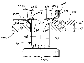
In Fig. 1, two panels 111 and 112 (metal,
glass fiber, composites, etc.) define the workpiece 110.
A main bore 113 extends in both panels--a counterbore
209 and a tapered countersink 114 in panel 111. The
bore and countersink have a common forwardly extending
axis 116.
- 6 -


CA 02200674 1997-08-25
The fine-grain, ductile, aluminum alloy rivet
118 has an axially extending shank 119 inserted
forwardly in and through bore 113, with clearance as
indicated. The rivet shank or tail projects forwardly
of panel 112. The rivet head 120 has an end face 121
(forming a ring-shaped dome) facing rearwardly and
spaced above the upper surface of 111. A cylindrical
section 208 of the rivet is bounded by cylindrical wall
209; and a forwardly tapered, frusto-conical section 122
of the rivet is spaced forwardly of section 208.
The rivet is progressively deformed as by
machine squeeze or by hammers 124 and 125 to flatten the
protruding head dome 121, and simultaneously to form
the upset or buck-tail 126 seen in Fig. 2a_. The arrows
at the head 120 cross section show the directions of
metal deformation during flattening of the dome. In
this regard, head metal adjacent tapered surface 122a_
tends to flow toward and around annular corner 130 at
the intersection of bore 113 with countersink 114, due
to the fact that force imparted to the rivet head by
deformation is centrally directed through the ring dome
crest toward the corner 130 defining a convexly annular
extrusion surface for rivet metal flow thereover.
The rivet, as in Fig. 1, has an annular
periphery 121_a of the end face 121 that is substantially
flush with the work surface 131; in addition, the end
face forms ring dome 132 protruding axially in a
rearward direction. This dome is generally ring-shaped
and extends about axis 116. The extent of rearward
protrusion of the dome is such that the entire head end


CA 02200674 1997-08-25
face 121 extends substantially above (prior to
deformation) and parallel with the work surface. Upon
completion of rivet deformation, as indicated at 121b_ in
Fig. 2~, the dome is substantially eliminated. End face
121 then protrudes between .001 and .006 inches above
the level of work surface 131.
The dome, being ring-shaped, is radially
located rearwardly of the countersink 114, whereby the
rivet head material remains in engagement with the
countersink and does not form a clearance therewith in
response to dome flattening. For best results, the dome
radially outer extent 132, which flares outwardly and
forwardly, is substantially entirely located in axially
spaced relation to the countersink, i.e., the tapered
countersink 114. The flare at 132a_, toward the head
outermost periphery, is at an angle controlled to assure
that its outer periphery is in a plane normal to axis
116. Further, the dome crest portion 132 is in
substantial axial alignment with the shank outer surface
119, and also work bore 113. The height "d" (see Fig.
3) of the crest above the level of 121_a is between 0.004
and 0.016 inches, for best results.
Accordingly, during the riveting process, the
rivet head tapered surface 122_a, throughout
substantially its entire length, remains seated against
the countersink 114, and no spring-back is produced to
the extent that clearance would develop, after
installation is completed.
In this regard, note that the central
concavity or recess at 133 in Fig. 3 of the head rear
_ g _


CA 02200674 1997-08-25
face becomes filled-in during rivet head deformation,
i.e., ring-dome flattening, and by shank material
back-filling as the shank column collapses and expansion
occurs. Deformation forces, indicated by the arrows in
Fig. 2 remains concentrated in alignment with the
countersink 114, whereby the head metal is constantly
forcibly urged toward that countersink to prevent
development of clearances. Consistency of complete
filling of recesses 133 in multiple rivets holding the
sheets clamped together is obtained by use of
fine-grained, ductile aluminum alloy, as referred to
below.
As riveting proceeds, the head metal bounded
by head wall 209, and located between dome 132 and
section 122, is typically deformed toward work
counterbore 209 (see Fig. 3) to fill the annular
clearance.
In actual practice, and as regards production
rivets, and for best results, when the dome is flattened
during rivet deformation, the rivet head side wall is
radially expanded and pushes outwardly against the
workpiece counterbore side wall to deform the latter
radially outwardly.
Fig. 3 shows a minimum head diameter (at 209),
maximum counterbore (at 210) relationship, whereby the
rivet head seats forwardly at 114, as shown; and Fig. 4
shows a maximum head diameter (at 209), minimum
counterbore (at 210) relationship, whereby the rivet
head seats rearwardly so that dome 132 protrudes
rearwardly from the work, prior to deformation.
_ g _


CA 02200674 1997-08-25
Upon deformation, counterbore 210 is expanded
radially outwardly by expansion of wall 209, as the dome
is flattened. The desired deformation of the dome 132
will occur during riveting, to maintain the walls 209
and 210 in radial compression and peripheral tension, as
desired. Also, a buck-tail is formed, as described
herein, for clamp-up creation.
In both Figs. 3 and 4, fine-grained aluminum
shank metal is extruded upwardly (see arrow 400) to fill
the recess bounded by the ring dome, during dome
flattening, and the top of the rivet head remains above
(i.e., rearward of) the plane of the work surface 131.
Typically, the rivet metal (which preferably
consists of fine-grained aluminum alloy, for enhancing
metal flow at 400) is softer than the work metal. For
example, the work panel has a tensile strength
substantially in excess of the rivet tensile strength,
for best results. Thus, the rivet and work will expand
and contract at rates to prevent radial gaps during
temperature change.
In a typical example, the head maximum
diameter is within the range .258 to .256 inches; and
the head side wall has an axial length of about .012 to
.042 inches. Also, the side wall length plus the axial
length of the head that tapers toward the shank, is
within the range .022 and .104 inches.
Referring now to Fig. 5, it is like Fig. 3,
but shows elements axially exploded. Clearances are
shown between wall 209 and counterbore 210, as exist
upon rivet insertion (but prior to deformation), and
- 10 -


CA 02200674 1997-08-25
between shank 119a_ and bore 113. Also, merely for
better identification, slight axial separation is shown
between tapered seat 114 and head tapered surface 114
(120° taper angle as seen in Fig. 1), and between convex
corner 130 and concave outer surface 223 of transitional
section 220.
The volumes of the cylindrical section 208,
frusto-conical section 122, and transitional section 220
are controlled, or predetermined, in relation to the
dimensions diameter of the workpiece bore 113, and the
dimensions (axial and radial) of the workpiece
counterbores 114 and 210, such that upon flattening of
the dome upon rivet deformation, the dome has a
flattened surface which lies between limits defined as
about
- flush with the workpiece outer surface
- protruding 0.006 inches from the
workpiece outer surface.
This assures aerodynamic flushness, and is assured by
use of the fine-grained aluminum alloy of the rivet, to
achieve desired metal flow, as described.
Another important aspect lies in defining and
maintaining two radii R1 and RZ, such that RZ is between
95% and 75% of R1, (50-25% difference) where:
- Rl is the radius of concave surface 223
in axial radial planes (surface 223 being
annular)
- RZ is the radius of workpiece convex
surface 130, in axial radial planes,
surface 130 being annular and slidably
- 11 -


. ~ CA 02200674 1997-08-25
engaged by surface 223 upon rivet
deformation.
When these relationships are maintained, along
with taper angularity of surfaces 114 and 122_a as shown,
(surface 114 intersecting surface 130, and surface 122_a
intersecting surface 223), the shear bearing support of
the rivet is optimized, while tension pull-through
capability of the rivet is assured. This advantage is
realized even when installed in the thinnest possible
sheet (i.e., near knife-edge condition), the areas 300
and 301 (Fig. 2) around the rivet head remain constant,
assuring a high degree (40% minimum of the sheet) of
shear bearing area of the sheet.
Fig. 5 also shows the annular crest portion
132 as located between radially inner and outer limits
(see lines 260 and 261 parallel to axis 116) the radial
gap 262 between lines 260 and 261 being less than 25% of
the radial dimension 264 of the dome cross section, the
gap being in alignment with the shank outer surface.
Comparison of Figs. 6_a and 6~ show that during
rivet deformation, head wall 209 moves radially
outwardly (leftwardly) to engage bore wall 210; and wall
209 further displaces wall 210 leftwardly by amount S1,
the final wall positions indicated at 209' and 210'. At
the same time, shank wall 223 moves radially outwardly
(leftward) and engages bore wall 113; and wall 223
further displaces wall 113 leftwardly by approximate
amount S2, the final wall position indicated at 223' and
113'. In actuality, wall 223' extends at an angle a
relative to its initial position 223, wall 223' flaring
- 12 -


. ~ CA 02200674 1997-08-25
in direction 240. As later described, a "buck-tail" is
formed at the shank end portion, gripping the edge of
the hole in the work, so that equal clamping forces are
produced between the buck-tail and the head angular
portion. Further, rivet metal is displaced (see arrow
241) toward the head recess about which the dome 132
extends, in Fig. 6~, to fill that recess, as the ring
dome is flattened, and the flattened top or rearward
surface 403 is maintained above the level of sheet
surface 431. See also head annular portion 432 formed
by the periphery of the head above extending to adjacent
surface 431, maintaining head surface 403 above the
level of 431. As a result, the deformed rivet locks the
work sheets 111 and 112 in clamped-together condition.
See arrows 420 and 421 in Fig. 2.
For best results the rivet is formed from
fine-grained aluminum alloy wire selected from the
following table group, said selected wire having grain
size and physical characteristics, as listed in the
following table:
Shear


Elongation Strength Grain
Size


Alloy & Diameterin in 2 Inches Min. Max. Maximum


Temper Inches Minimum s Ksi Ksi ASTM E:112


2 5 2017-T4 .092 0.565 14 35 41 7
thru


2024-t4 .092 0.565 13 37 N/A 6
thru


2117-T4 .092 0.565 18 26 N/A 5
thru


2219-T62 .092 0.565 12 30 N/A 5
thru


7050-T73 .092 0.565 14 41 46 5
thru


7050-T715 .092 0.565 15 35 41 5
thru


In this regard, grain size number is inversely
related to actual grain size, and is measured in
- 13 -


CA 02200674 1997-08-25
accordance with ASTM E:112. The grain size numbers are
larger than those previously obtainable, whereby smaller
grains are now made possible leading to substantially
increased flowability of metal in the shank to fill the
recess surrounded by the ring dome. This in turn
enables better consistency in deformation of multiple
rivets in such manner as to hold the work sheets in
retained clamp-up condition, i.e., for reduced fretting.
"Elongation" in the table refers to measured
separation of benchmarks for a specimen during a tension
test, to failure. Prior elongation values of up to 11
or 12 are herein exceeded by use of fine-grained
aluminum alloy, enhancing ductility to promote shank
metal flow toward the recess to be filled in.
Therefore, the present rivet metal is characterized by
high elongation. Also, expansion of the shank adjacent
the outer surface of the lower work sheet causes such
gripping engagement with that sheet as to facilitate
production of clamp-up force as the buck-tail is formed.
Fig. 7 views (a)--(e), show a typical example
of deformation of the present rivet. The 120° rivet
configured as shown is inserted into the structure
comprised of two sheets 111 and 112, or metallic
materials of the composition referred to, with the holes
and counterbores prepared within specified tolerance.
The riveting tooling is employed to apply force to the
rivet "ring domed" head 120, and also on the terminal
end 118, simultaneously. Note that the ring dome crest
is spaced at about .010 inches above the work surface
131, in view 7(a).
- 14 -


CA 02200674 1997-08-25
As shown in Fig. 7 (b) , as the squeeze force
increases, the rivet shank 118 begins to swell to form
an annular taper or wedge area at 118b_, under the work
lower surface 112_a. Enlarged extent 118 c_ of the shank
is in axial alignment with the head 120. The ring dome
132 is simultaneously being flattened.
In Fig. 7(b), the dome crest has been
flattened to a spacing of about .008 inches from the
work surface 131; and the bottom surface 132a_ of the
concave recess has been pushed up to a level of about
.003 inches from work upper surface level 131. This
corresponds to backfill of the recess. Also, clamp-up
creation begins, as referred to below. Fig. 7(c) shows
the dome crest level reduced to about .0075 inches from
the surface 131, and the recess bottom surface 132a_
pushed up to a level of about .0055 inches from the work
surface .
With continued squeeze force application, the
tapered shank at 118_d is deformed, as in Fig. 7 (d) to
grippingly or flatly engage at 118c_ the work lower
surface 112_a, about the hole 113, creating compressive
clamping pressure toward the 120° tapered underside of
the head 120. Note that the ring dome crest being
flattened is reduced to a level about .007 inches from
the work surface, and the bottom surface 132_a of the
recess is now elevated to about .0065 inches from that
surf ace .
As more squeeze force is applied, the shank
118 is deformed to form a "buck-tail" shape, adj acent
3 0 the underside 112_a of the work, as seen in Fig . 7 ( a ) .
- 15 -


CA 02200674 1997-08-25
The ring-dome crest and the bottom of the recess are now
at the same spacing, .005 inch, from the work surface,
as shown, whereby the head is now flattened. Such
opposite direction deformation of the ring-dome crest
(down) and the concave recess 132_a (up), which is
facilitated by the fine-grain metallic composition of
the rivet metal, further facilitates desired, consistent
deformation of the rivets to the Fig. 7(e) condition
shown, with retained clamp-up of the work sheets. Such
clamp-up increases fatigue life of the joint, and the
tightly sealed riveted connection inhibits corrosion
development at the work interfaces.
Grain size, for example, is related to average
nominal inches per grain, to grain (edge intercept)
count, for a total of 50 intercepts, and to average
intercept distance, according to the following table:
Minimum Distance


Average NominalAverage InterceptPer Inch For


Grain Size Inches/Grain Distance 50 Intercepts


2 0 5. .0025" .00223" .1115"


5.5 .0020" .00187" .0935"


6 .0018" .00157" .0785"


6.5 .0014" .00132" .0660"


7 .0012" .00111" .0555"


2 5 7.5 .0010" .000940" .0470"


8 .0009" .000787" .03935"


8.5 .0007 .000662" .03310"


9 .0006 .000557" .02785"


30 4.4 RULES
1. Penetration into a grain in the direction
of the test line are scored as half (1/2)
grains.
- 16 -


CA 02200674 1997-08-25
2. Do not count the ends of the test line as
an intercept.
3. A grain extending into the line shall be
counted as one (1) grain.
4. Two (2) or more grain juncture extends
into a line must be counted as one and
one half (1-1/2) grain.
5. Two (2) intercepts with the same grain
shall be counted, total two (2).
Determination of grain size in a sample wire,
from which rivets of the invention are to be formed,
involves for example counting 50 (i.e., a pre-determined
number of) successive grains (at 100 x magnification)
along a straight path crosswise of the end face of a
sheared wire, and determining the length dimension,
i.e., distance occupied by the 50 grains, then dividing
that distance by 50 to determine average intercept
distance. This distance is related to average nominal
inches/grain, and to Grain Size, as referenced herein,
as shown in the above table.
As indicated herein, a sample of wire is
usable for the rivet only, if the determined fine Grain
Size is between 5 and 9, i . a . , the average determined
intercept distance (as determined by counting, above)
lies between .00223 inch and .000557 inch.
It is a further objective of the method of the
invention to enable formation of a larger buck-tail
diameter, as related to rivet initial shank diameter,
during rivet deformation at installation. Such
formation is enabled by use of the fine-grained aluminum
- 17 -


CA 02200674 1997-08-25
alloy described herein. For example, the buck-tail can
now be formed to have a minimum diameter which is at
least 1.4 times the initial undeformed shank diameter,
for a finished rivet. In another example, 7050-T73
alloy is formed to have a minimum buck-tail diameter
which is at least 1.5 times the initial shank diameter.
This compares with a buck-tail diameter about 1.3 time
the initial shank diameter for prior rivet materials.
Large buck-tails facilitate better retained clamp-up,
the benefits of which are described above.
Referring now to Fig. 8, it shows a rivet 118
having a thin barrier material 400 on its surfaces, such
as at 400 on end face 121 of ring dome 121_a, 400b_ on
the head outer wall 209, and at 400 on the
frusto-conical or tapered surface 122_a. The barrier
thickness is typically between .0002 and .002 inches;
and the protective barrier typically consists of a
sealant, or a coating, or a sealant applied over a
coating.
As examples, the coating may consist of
aluminized particles in a carrier, such as a phenolic
resin, baked onto the rivet surfaces at temperatures
between 200° and 450°F., to volatilize the carrier. A
commercial example is TecKote 8-G or HI-COTE 1.
A sealant example is a flexible polysulfide
epoxy rubber in a sprayable solution. A commercial
example is Courtauld's PRC1436GE2.
Fig. 9, shows the barrier material layer 400b_
displaced outwardly during head expansion toward and
- 18 -


CA 02200674 1997-08-25
into the work counterbore wall 210, i.e., into
interstices at that wall.
Fig. 10 is a greatly magnified view, showing
surface roughness 209_a and 210sa at walls 209 and 210,
forming interstices into which the barrier material 400
penetrates, as shown. Note the variable thickness and
jagged configuration of the material 400b_ filling and
sealing the interstices.
Note also that flattening of the dome results
in extrusion of the barrier material to provide an
overlap at 400 extending on the work, adjacent the work
bore edge, with added sealing effect. Barrier layers
400 and 400b_ may desirably extend to that overlap.
Fig. 9 also shows barrier layer 400c_ urged
against the tapered counterbore at 114a_ of the work
sheet 111, to fill interstices. This eliminates the air
gap 410 as formed in prior installations, as per Fig.
11, where no sealant or coating is employed, as in the
present invention.
In Fig. 8, the volume of the dome 121 may
have a value A; the space between the walls 209 and 210
may have a volume B; and the volumes are such that, when
the dome is flattened during deformation, the wall 209
expands into volume A and pushes outwardly against side
wall 210 to deform it outwardly.
Further, the following relationships are
maintained:
h) the ratio B/A being within the range
1.20:1 to 70:1,
- 19 -


CA 02200674 1997-08-25
i) the head end face formed to define a
recess bounded by the ring-shaped dome, and
j) dome flattening is carried out so that
the shear load bearing areas around the expanded rivet
head have thickness which remains at least 40 0 of the
thickness of the workpiece sheet in which the head is
located.
Also, A and B have one of the following two
relationships:
xl A is within the range .0000120 cubic
inches and .000190 cubic inches; and
B is provided to be within the range
.0000125 cubic inches and .00090
cubic inches,
x2 A is within the range .0000013 cubic
inches and .000013 cubic inches; and
wherein B is within the range
.000029 cubic inches and .00088
cubic inches.
In addition, A is provided to be within the
range .0000120 cubic inches and .000190 cubic inches;
and B is provided to be within the range .0000125 cubic
inches and .00090 cubic inches. Typically, the head
maximum diameter is within the range .121 to .521
inches, and the head side wall has an axial length of
about .012 to .042 inches.
The method includes forming the dome to have
an annular crest portion in substantial axial alignment
with the shank outer surface, and the dome radially
outer extent which defines only about half of the dome
- 20 -


CA 02200674 1997-08-25
being located in axially spaced relation to a forward
taper defined by the forwardly tapered frusto-conical
section, the dome crest portion being rearwardly convex
in axial radial planes. The outermost annular extent of
the crest if located approximately in alignment with the
outer surface of the shank.
Both the rivet and wall are metallic, the
rivet metal softer than the wall metal, and the rivet
consists of one of the following:
i) aluminum
ii) aluminum alloy
iii) titanium
iv) titanium alloy
v) CRES alloy.
- 21 -

Representative Drawing
A single figure which represents the drawing illustrating the invention.
Administrative Status

For a clearer understanding of the status of the application/patent presented on this page, the site Disclaimer , as well as the definitions for Patent , Administrative Status , Maintenance Fee  and Payment History  should be consulted.

Administrative Status

Title Date
Forecasted Issue Date 2001-05-01
(22) Filed 1997-03-21
(41) Open to Public Inspection 1997-11-24
Examination Requested 1997-12-11
(45) Issued 2001-05-01
Deemed Expired 2010-03-22

Abandonment History

There is no abandonment history.

Payment History

Fee Type Anniversary Year Due Date Amount Paid Paid Date
Registration of a document - section 124 $100.00 1997-03-21
Application Fee $150.00 1997-03-21
Request for Examination $200.00 1997-12-11
Maintenance Fee - Application - New Act 2 1999-03-22 $50.00 1999-01-27
Maintenance Fee - Application - New Act 3 2000-03-21 $50.00 2000-03-16
Registration of a document - section 124 $100.00 2000-07-20
Final Fee $300.00 2001-01-30
Maintenance Fee - Application - New Act 4 2001-03-21 $100.00 2001-01-30
Maintenance Fee - Patent - New Act 5 2002-03-21 $150.00 2002-03-05
Maintenance Fee - Patent - New Act 6 2003-03-21 $150.00 2003-03-05
Maintenance Fee - Patent - New Act 7 2004-03-22 $200.00 2004-03-04
Maintenance Fee - Patent - New Act 8 2005-03-21 $200.00 2005-03-04
Maintenance Fee - Patent - New Act 9 2006-03-21 $200.00 2006-03-01
Expired 2019 - Corrective payment/Section 78.6 $450.00 2007-01-29
Maintenance Fee - Patent - New Act 10 2007-03-21 $250.00 2007-03-01
Maintenance Fee - Patent - New Act 11 2008-03-21 $250.00 2008-02-29
Owners on Record

Note: Records showing the ownership history in alphabetical order.

Current Owners on Record
ALLFAST FASTENING SYSTEMS, INC.
Past Owners on Record
AURENTZ, JOHN A.
BRILES, FRANKLIN S.
Past Owners that do not appear in the "Owners on Record" listing will appear in other documentation within the application.
Documents

To view selected files, please enter reCAPTCHA code :


To view images, click a link in the Document Description column. To download the documents, select one or more checkboxes in the first column and then click the "Download Selected in PDF format (Zip Archive)" or the "Download Selected as Single PDF" button.

List of published and non-published patent-specific documents on the CPD .

If you have any difficulty accessing content, you can call the Client Service Centre at 1-866-997-1936 or send them an e-mail at CIPO Client Service Centre.


Document
Description 
Date
(yyyy-mm-dd) 
Number of pages   Size of Image (KB) 
Cover Page 1998-02-18 1 78
Abstract 1997-03-21 2 46
Description 1997-03-21 19 693
Abstract 1997-08-25 2 44
Description 1997-08-25 20 667
Claims 1997-08-25 14 413
Drawings 1997-08-25 9 143
Claims 1997-12-11 11 444
Cover Page 1998-01-30 2 89
Claims 1997-03-21 17 442
Drawings 1997-03-21 7 162
Cover Page 2001-04-12 2 90
Description 1999-11-02 20 667
Representative Drawing 1998-01-30 1 8
Representative Drawing 1998-02-18 1 5
Representative Drawing 2001-04-12 1 9
Prosecution-Amendment 1999-09-13 2 3
Prosecution-Amendment 1999-11-02 2 69
Fees 2000-03-16 1 28
Correspondence 1997-08-25 46 1,290
Assignment 2000-07-20 2 71
Correspondence 2000-08-17 1 1
Prosecution-Amendment 1997-12-11 15 601
Prosecution-Amendment 1997-12-11 1 25
Correspondence 1997-04-15 1 35
Assignment 1997-03-21 6 192
Fees 1999-01-27 1 32
Assignment 2000-09-08 1 30
Correspondence 2001-01-30 1 27
Fees 2001-01-30 1 30
Prosecution-Amendment 2007-01-29 2 107
Correspondence 2007-03-26 1 12