Language selection

Search

Patent 2200861 Summary

Third-party information liability

Some of the information on this Web page has been provided by external sources. The Government of Canada is not responsible for the accuracy, reliability or currency of the information supplied by external sources. Users wishing to rely upon this information should consult directly with the source of the information. Content provided by external sources is not subject to official languages, privacy and accessibility requirements.

Claims and Abstract availability

Any discrepancies in the text and image of the Claims and Abstract are due to differing posting times. Text of the Claims and Abstract are posted:

  • At the time the application is open to public inspection;
  • At the time of issue of the patent (grant).
(12) Patent: (11) CA 2200861
(54) English Title: DEVICE FOR MAKING A WIRE STRAND WITH CHANGING TWIST DIRECTION
(54) French Title: DISPOSITIF DE TORONNAGE DE CABLES EN SENS ALTERNE
Status: Expired and beyond the Period of Reversal
Bibliographic Data
(51) International Patent Classification (IPC):
  • H01B 13/02 (2006.01)
(72) Inventors :
  • SEIBERT, GERHARD (Austria)
(73) Owners :
  • BERGSMANN, LUDWIG
(71) Applicants :
  • BERGSMANN, LUDWIG (Germany)
(74) Agent: SMART & BIGGAR LP
(74) Associate agent:
(45) Issued: 2003-08-12
(86) PCT Filing Date: 1995-06-28
(87) Open to Public Inspection: 1996-01-11
Examination requested: 2002-04-18
Availability of licence: N/A
Dedicated to the Public: N/A
(25) Language of filing: English

Patent Cooperation Treaty (PCT): Yes
(86) PCT Filing Number: PCT/AT1995/000137
(87) International Publication Number: WO 1996000970
(85) National Entry: 1997-03-24

(30) Application Priority Data:
Application No. Country/Territory Date
A 1272/94 (Austria) 1994-06-28

Abstracts

English Abstract


A device for stranding cables from individual wires with alternate directions
of lay (SZ stranding) in which there are a fixed guide (1) with drillings to
accept the individual wires and several spaced storage discs (4) drivable in
alternate directions and also with drillings to accept the individual wires to
be stranded or a laying disc (6) drivable via drive discs (7) and transmission
components (9), in which there is a common drive (8) for at least some of the
drive discs (7), whereby there is a torsion elastic shaft (15) of any cross-
section between the drive (8) and the drive discs (7).


French Abstract

L'invention concerne un dispositif de toronnage de câbles en sens alterné (câblage SZ), à partir de fils individuels, qui comprend un guide (1) fixe comportant des trous pour recevoir les fils individuels, et des disques de stockage (4) disposés à distance les uns des autres, entraînables dans des sens alternés et également pourvus de trous pour recevoir les fils individuels à toronner, ou bien un disque d'alimentation (6). Ces disques peuvent être entraînés par l'intermédiaire de poulies motrices (7) et d'éléments de transfert (9). Il est prévu un système d'entraînement commun pour au moins une partie des poulies motrices (7), un arbre (15) élastique en torsion de section quelconque étant disposé entre le système d'entraînement (8) et les poulies motrices (7).

Claims

Note: Claims are shown in the official language in which they were submitted.

CLAIMS:
1. A device for making a wire strand with changing
twist direction (SZ-stranding) from individual wires,
comprising:
a fixed guide provided with bores for passage of
individual wires;
a plurality of storing disks trailing the fixed
guide and arranged in spaced-apart disposition, said storing
disks having bores for passage of the individual wires to be
stranded;
a laying disk trailing the plurality of storing
disks; and
drive means for operating the storage disks and
the laying disk in changing directions, said drive means
including a plurality of drive disks and a like plurality of
transmission members, said drive disks and said transmission
members being so positioned that each of the storage disks
and the laying disk are operatively connected to a different
one of the drive disks via a different one of the
intermediate transmission members, said drive means further
including a motor operatively connected to at least some of
the drive disks, and a torsionally elastic shaft having a
random cross-section and extending between the motor and the
drive disks
.
2. The device of claim 1, and further comprising a
rigid shaft for coupling at least two neighboring drive
disks, with said neighboring drive disks and the associated
storage disks having different transmission ratios.
8

3. The device of claim 1 wherein the torsionally
elastic shaft is maintained under tension.
4. The device of claim 1 wherein the torsionally
elastic shaft is formed as an element selected from the
group consisting of torsion spring and torsion bar, and
connected to the drive disks in a torsion-free manner.
5. The device of.claim 4 wherein the torsionally
elastic shaft has a spring constant increasing in the
direction towards the motor.
6. The device of claim 1 wherein the torsionally
elastic shaft is formed by at least one tensed, extendible
filament-shaped or strip-shaped element which is guided
through eccentrically arranged bores of the drive disks and
secured to the drive disk closest to the motor.
7. The device of claim 6 wherein the eccentricity of
the bores in the drive disks increases in the direction
towards the motor.
8. The device of claim 1 wherein the torsionally
elastic shaft is formed by a cable or strip secured by a
spring.
9

Description

Note: Descriptions are shown in the official language in which they were submitted.


CA 02200861 2002-10-17
27392-20
DEVICE FOR MAKING A WIRE STRAND WITH
CHANGING TWIST DIRECTION
The invention relates to a device for making a
wire strand with changing twist direction (SZ-stranding)
from individual wires and in particular to a device of a
type a fixed guide provided with bores for receiving the
individual wires and a plurality of spaced apart storing
disks capable of being driven in changing directions and
also having bores for receiving the individual wires to be
stranded, and a laying disk capable of being driven via
drive disks and transmission members.
In known devices of this type, the laying disks
are driven by the associated driving disks via mechanisms
with correspondingly different speed increasing ratios.
This, however, has the disadvantage that relatively large
masses have to be braked within a short time and accelerated
again in the opposite direction. This is especially
disadvantageous for those laying disks which have a large
twisting angle.
It is the object of the invention to obviate these
disadvantages and to propose a device of the abovementioned
type where the direction of only relatively small masses
will have to be reversed.
The object of the invention is achieved by
providing a drive common to at least a portion of the drive
disks, wherein between the drive and the drive disks there
is disposed a torsionally elastic shaft having an arbitrary
cross-section. These features make it possible that at least
a portion of the drive disks connected to each other via the
torsionally elastic shaft does not require a separate speed
increasing mechanism, since this function is provided by the
1

CA 02200861 2002-10-17
27392-20
torsionally elastic shaft. The decreasing twisting angles
required for proper stranding which decrease in relation to
the fixed guide, result from the decreasing twist of the
torsionally elastic shaft in relation to its fixed end.
According to one broad aspect of the invention
there is provided a device for making a wire strand with
changing twist direction (SZ-stranding) from individual
wires, comprising: a fixed guide provided with bores for
passage of individual wires; a plurality of storing disks
trailing the fixed guide and arranged in spaced-apart
disposition, said storing disks having bores for passage of
the individual wires to be stranded; a laying disk trailing
the plurality of storing disks; and drive means for
operating the storage disks and the laying disk in changing
directions, said drive means including a plurality of drive
disks and a like plurality of transmission members, said
drive disks and said transmission members being so
positioned that each of the storage disks and the laying
disk are operatively connected to a different one of the
drive disks via a different one of the intermediate
transmission members, said drive means further including a
motor operatively connected to at least some of the drive
disks, and a torsionally elastic shaft having a random
cross-section and extending between the motor and the drive
disks.
A preferred embodiment of the invention for wire
stranding machines where large stranding forces for the
items to be stranded are required, includes at least two
adjacent drive disks coupled together via a rigid shaft,
with the drive disks having different speed increasing
ratios with respect to their associated laying disks.
2

CA 02200861 2002-10-17
' 27392-20
The twisting action is at all possible and can be
improved by maintaining the torsionally elastic shaft under
tension.
Preferably, the torsionally elastic shaft is
formed as a torsion spring or a torsion bar which is
connected to the drive disks in a torsion-free manner. This
is from an engineering standpoint, a very simple solution.
According to another feature of the present
invention, the spring constant of the torsion spring and the
torsion bar, respectively, increases in the direction
towards the drive. In this manner, a different stiffness of
the spring or rod, as the case may be, is obtained along the
length of the torsion spring or the torsion bar,
respectively, whereby the mass inertia of the torsionally
elastic shaft can be compensated at high accelerations.
In one embodiment of a device of the invention the
excursion of the filament-shaped or strip-shaped element and
the lengthening caused thereby, creates a corresponding
restoring force, resulting in an action similar to a torsion
spring, wherein, however, the filament-shaped or strip-
shaped element itself does not experience a significant
torsion. If the radial distance between the bores for
receiving the filament-shaped or strip-shaped element and
the rotation axis of the drive disks is increased when
moving in the direction from the fixed guide towards the
motor, then the twisting angles of the laying disks will in
turn decrease when moving from the region proximate to the
motor to the region proximate to the guide.
Advantageously, the torsionally elastic shaft is
formed by a cable or strip secured by a spring. In this
3

CA 02200861 2002-10-17
' 27392-20
manner, overloading of the cable can positively be
prevented.
The invention will now be explained in further
detail with reference to the drawing, in which:
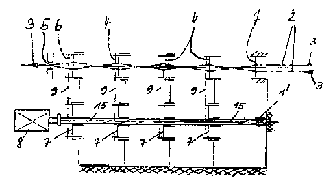
FIGS. 1 and 2 show schematically two different
embodiments of devices according to the invention,
FIG. 3 shows a schematic, sectional view of a
device according to the invention, and
FIGS. 4 and 5 show further embodiments of the
invention.
3a

i2i1?~1396 18:2a 21~'~44'4~3'~ HEhJR''~' f~t f=EIEt?EI~Ehs P~(aE a
In the embodirr~ents according to FIGS. 1 and 2, there is provided a fixed
guide 1 provided with bores arranged concentrically with respect to a center
axis
for receiving individual wires 2.
Subsepuent to the fixed guide 1 there are arranged ess~er~tially equally
spaced storing disks 4 along the pulling direction of the i~edividuei wires 2
which
is indicated by arrows 4, wherein the storing disks 4 are a~Iso provided with
bores
arranged concentrically with respect to a rotation axis of the laying disks 4
far
receiving individual wires 2. In this use, the storing disks 4 and a haying
disk 6
are capable of being driven in changing direction.
A cable guide ~ is provided following the laying disk 4 through u~rhich the
cable is wi~ndrawn.
1~ The storing disks 4 and the laying dish B are each driven via a
transmission member 9, such as a belt, by the drive disks 7 which are coupled
to
a motor 8.
in both embodiments, a torsion spring 15 is provided as a coupling
element which in the ernbodimant of FIG. 1 is secured to a part of the frame
in
the area of a fixed guide 1'.
4

12,~~17~199F 18:'7 21224::2~.~:3 HENR'~l IN FEIEr~F_TSEhJ P~~aE 06
f~ ~~"
In the embodirt~ent of FIC;. 2, the torsion spring is provided only for a
portion of the laying disks 4, i.e. coupled to the two laying disks closest to
the
motor 8.
Iry both embodiments, the drive disks B are coupled to th~ laying disks ~.
and the laying disk 6, respectively, via the belt 9. In this case, for all of
the drive
disks 7 coupled to the torsion spring 15 the same speed increasing ratio may
be
provided with respect to the associated storing disks 4 and laying disk 6,
respectively.
a
In the embodiment of 1~1G. 2, the two drive disks 7 closest to the fixed
guide 'I are coupled together via a rigid shaft 10 which is in tum couplad at
16 to
the torsion spring 15. In contrast to the speed increasing ratio of the two
drive
disks 7 closet to the motor 8, however, the speed increasing ratios for these
1S drive disks with respect to their associated storing disks 4 may be
different.
At the rotatably supported end of the rigid shaft 10 facing away from the
coupling 1~, a limit stop is provided for limiting the twisting angle of the
laying
disk ~ apt tftat respective position, the positions of the limit stop being
arranged in
20 such a way that the respective laying disk 4 is capable of rotating in both
SZ-
directions by the corresponding rotation angle.

1«'1~~1E~1E 28:27 2222442<=;.~ HEP~i~'Y' M ~EIE~;EZSEhJ PFai,E ~7
The difference of the twisting angles between the storing disk 4 which is
closest to the f$xed guide 1 and is stilt or is already driven by the spring,
and tt~e
laying disk 5 has to be equa$ or larger than the twisting angle required by
the
laying disk for acceleration. In this way, tha motor can be rapidly brought to
its
nominal speed and the reversing region from left to right or vice versa on the
stranded item can be kept short.
t=iG. ~ shows that the motor 5 and its shaft 11, rraspectiveiy, are coupled
in a torsian-free manner to the drive disk 7 which, in turn, is coupled in a
torsion-
free manner to the torsion spring 15. The drive disk ~ associated with the
storing
disk 4 closest to the motor 8 is also coupled in a torsion-free manner to tl~e
torsion spring 15, with the torsion spring 15 fixedly secured in a support 12
which is in turn supported by a frame portion 13 of the device.
In the embodiment of IFIG. 4, the torsion spring 15 is replaoed by a torsion
bar which provides an identical effect and function as if a torsion spring 9
was
used.
FIG. 5 shows an embodiment where the torsionaily elastic shaft is formed
by at least one taught, extendible filament-shaped or strip-shaped element 18
which is guided through eccentrically arranged bores 1 S of the drive disks 6
and
secured to the drive disk 6 closest to the rriotor ~, wherein the eccentricity
of the
6

12!1';'195E ~~i:27 21~'24~:'~~E.~ HE~R'~' M FE=EREI~Eta E'~GE ~E
0
bores in the drive disks 6 which are penetrated by the filament-sf~aped
element,
may increase in the direction tovvuaards the motet $. The cable or strip 18 is
preferably secured by a spring which is net shown, alternatively or irt
addition,
the cable may also comprise an elastically extendible material, such as
rubber,
plastic or the like, and may not be prestressed.
7

Representative Drawing
A single figure which represents the drawing illustrating the invention.
Administrative Status

2024-08-01:As part of the Next Generation Patents (NGP) transition, the Canadian Patents Database (CPD) now contains a more detailed Event History, which replicates the Event Log of our new back-office solution.

Please note that "Inactive:" events refers to events no longer in use in our new back-office solution.

For a clearer understanding of the status of the application/patent presented on this page, the site Disclaimer , as well as the definitions for Patent , Event History , Maintenance Fee  and Payment History  should be consulted.

Event History

Description Date
Time Limit for Reversal Expired 2015-06-29
Letter Sent 2014-06-30
Inactive: Office letter 2007-02-27
Inactive: Corrective payment - s.78.6 Act 2007-01-19
Grant by Issuance 2003-08-12
Inactive: Cover page published 2003-08-11
Pre-grant 2003-05-23
Inactive: Final fee received 2003-05-23
Inactive: Adhoc Request Documented 2003-02-21
Inactive: Office letter 2003-02-21
Inactive: Correspondence - Prosecution 2003-01-15
Notice of Allowance is Issued 2002-12-03
Letter Sent 2002-12-03
Notice of Allowance is Issued 2002-12-03
Inactive: Approved for allowance (AFA) 2002-11-25
Amendment Received - Voluntary Amendment 2002-10-17
Amendment Received - Voluntary Amendment 2002-10-07
Inactive: S.30(2) Rules - Examiner requisition 2002-06-17
Letter Sent 2002-06-12
Inactive: Entity size changed 2002-06-07
Amendment Received - Voluntary Amendment 2002-05-09
Request for Examination Received 2002-04-18
Request for Examination Requirements Determined Compliant 2002-04-18
All Requirements for Examination Determined Compliant 2002-04-18
Letter Sent 1997-09-24
Inactive: Single transfer 1997-07-28
Inactive: Notice - National entry - No RFE 1997-06-19
Inactive: IPC assigned 1997-06-18
Inactive: First IPC assigned 1997-06-18
Inactive: Notice - National entry - No RFE 1997-06-10
Inactive: Courtesy letter - Evidence 1997-04-29
Application Published (Open to Public Inspection) 1996-01-11

Abandonment History

There is no abandonment history.

Maintenance Fee

The last payment was received on 2003-05-21

Note : If the full payment has not been received on or before the date indicated, a further fee may be required which may be one of the following

  • the reinstatement fee;
  • the late payment fee; or
  • additional fee to reverse deemed expiry.

Please refer to the CIPO Patent Fees web page to see all current fee amounts.

Owners on Record

Note: Records showing the ownership history in alphabetical order.

Current Owners on Record
BERGSMANN, LUDWIG
Past Owners on Record
GERHARD SEIBERT
Past Owners that do not appear in the "Owners on Record" listing will appear in other documentation within the application.
Documents

To view selected files, please enter reCAPTCHA code :


To view images, click a link in the Document Description column. To download the documents, select one or more checkboxes in the first column and then click the "Download Selected in PDF format (Zip Archive)" or the "Download Selected as Single PDF" button.

List of published and non-published patent-specific documents on the CPD .

If you have any difficulty accessing content, you can call the Client Service Centre at 1-866-997-1936 or send them an e-mail at CIPO Client Service Centre.


Document
Description 
Date
(yyyy-mm-dd) 
Number of pages   Size of Image (KB) 
Representative drawing 2003-07-09 1 10
Cover Page 2003-07-09 1 40
Cover Page 1997-10-30 1 45
Abstract 1997-03-24 1 20
Description 1997-03-24 7 201
Claims 1997-03-24 2 61
Drawings 1997-03-24 3 77
Claims 2002-10-17 2 60
Description 2002-10-17 8 248
Representative drawing 1997-10-30 1 6
Notice of National Entry 1997-06-19 1 202
Notice of National Entry 1997-06-10 1 202
Courtesy - Certificate of registration (related document(s)) 1997-09-24 1 118
Reminder - Request for Examination 2002-03-04 1 119
Acknowledgement of Request for Examination 2002-06-12 1 179
Commissioner's Notice - Application Found Allowable 2002-12-03 1 160
Maintenance Fee Notice 2014-08-11 1 172
Correspondence 2003-02-21 1 15
Correspondence 2003-05-23 1 31
Fees 2003-05-21 1 36
Fees 2002-05-24 1 39
Correspondence 1997-04-29 2 48
PCT 1997-08-14 7 236
PCT 1997-07-15 8 228
PCT 1997-03-24 13 450
Fees 2000-05-16 1 39
Fees 2004-06-03 1 38
Correspondence 2007-02-27 1 12