Note: Descriptions are shown in the official language in which they were submitted.
CA 02201038 2005-07-29
- 1 -
"SUB-ASSEMBLY FOR LUBRICATING ROCK DRILL BIT"
Technical Field
The present invention relates to the lubrication of
drill bits used in rock drilling operations and in
particular to a sub-assembly to provide lubricant to the
bearings and wear surfaces of a rock drill bit.
Drilling into bedrock, for example, to enable
explosive charges to be placed for excavating ore in
open-cut mining operations can be carried out by either
rotary air blast drills (RAB-drills) and/or hammer
drills.
The drill bit is mounted at the forward end of a
drill string consisting of sections joined together by
appropriate connectors at either end of each section. A
stabiliser section maybe located behind the actual drill
bit to centre the drill bit within the bore hole. Two
standard connection threads are generally used in the
drilling industry, namely, BECO and API, and a crossover
connector is often required to accommodate sections and
sub-assemblies having different connection threads.
In the case of RAB-drills, air at high pressure
(typically 40 psi) and volume (750 to 2000 cubic feet per
minute) is delivered through a bore in the drill string
to the drill bit. The vast majority of the air supplied
to the drill bit which may, for example, be a blade or
roller type bit, exits from a jet nozzle arranged in the
interior dome area of the body of the bit which rotatably
mounts the bit cones. The air jet is used to convey the
debri.s created by the drilling operation away from the
drilling work face of the borehole. This debris travels
up the borehole past the drill string at a typical
bailing velocity of 5,000 to 7,000 feet per minute
depending on the size of the borehole and the drill
string. A portion of the air flow is directed through
CA 02201038 2005-07-29
- 2 -
so called air circulation passages in the drill bit body
for cooling the bearings of the bit cones.
The debris produced includes particulate matter and
dust. To reduce the dispersion of dust into the
environment, which has deleterious effects on both
equipment and personnel, the debris can be sprayed with
water. With conventional drill bits, the water is
supplied with the air through the drill string into the
drill bit where it exits together with the air through
the jet nozzle. However, in addition to suppressing
dust, the water also causes corrosion, in particular of
the bearings. It also produces a slurry which causes
wear of the cutting surfaces of the drill bit, reducing
the life of the bit and reducing drill penetration rates.
Both these are detrimental to operation costs since the
drill bit is a costly item to replace and the drill
penetration rate is the single most important factor in
operational costs.
It is known with conventional roller type bits to
provide in the air circulating passages so-called air
bearing filters to reduce water ingress into the
bearings. However, none of the air bearing filters
commercially available effectively reduce water ingress
to the bearings and corrosion problems which reduce bit
life.
W093/20331 (which is the publication number of the
application PCT/AU93/00141, as published on 14 October
1993, a patent application entitled "Sub-Assembly for
Rock Drilling" to this same Applicant) discloses a sub-
assembly for dust suppression in rock drilling which
effectively separates the blast air from the water such
that air only is passed onto the drill bit while the
water is injected into the upward travelling debris
behind the drill bit. The sub-assembly is inserted in
the drill string behind the drill bit and includes a
spiral raceway arranged within an inner tubular housing
which itself is arranged co-axially within an outer
tubular housing. The air-water mixture enters the inner
CA 02201038 2005-07-29
- 3 -
housing and is centrifuged as it passes along the spiral
raceway so that the liquid is expelled through a number
of orifices along the inner housing wall and into the
chamber between the inner and outer housing. The
separated water is directed through apertures in the
outer housing into the drill bore. At the end of the
spiral raceway, essentially air only passes through
openings into the drill bit. Thus, corrosion of the
bearings due to water ingress is substantially avoided
whilst still ensuring proper cooling of the bearings
through the air circulation passages.
With conventional RAB-drills attached to the drill
string it has also been proposed to introduce a water
soluble lubricant into the air-water mixture for
lubricating the bearings of the bit in order to reduce
water induced corrosion and extend bit life. One such
additive lubricant is known under the trade name SPHERE-
TRI-LUBE, distributed by Sheer Drilling Supplies,
Calgary, Alberta, Canada. The lubricant is added to
provide a ratio of 1:150 lubricant to water. However,
such addition of lubricants to the air-water mixture does
not entirely suppress corrosion and due to the layout of
conventional RAB-drill bits, most of the lubricant is
expelled with the air-water mixture through the jet
nozzle and only a small amount actually is directed into
the bit housing air channels to lubricate the bearings.
Also, drill bit life is only minimally extended as
compared to drill operations without additive lubricant.
Also, this method of introducing lubricant into the air-
water mixture would be fruitless where a dust suppression
sub-assembly of above described type is incorporated into
the drill string, since the lubricant would be separated
together with the water prior to reaching the drill bit.
It would thus be advantageous if the present
invention could provide a lubricating system for the
bearings and bearing surfaces within a rock drill bit,
CA 02201038 2005-07-29
- 4 -
i.e. . roller type bits, which provides a useful
alternative to existing methods of lubrication.
Disclosure of the Invention
According to a first aspect of the invention, there
is provided a lubricating sub-assembly for a rock drill,
comprising a housing with means to link the sub-assembly
into a drill string, preferably adjacent the drill bit, a
cavity being disposed within the housing for holding a
predetermined amount of a bearing lubricant. The sub-
assembly further incorporates means for communicating the
interior of the cavity with one or more air circulation
passages provided in the body of the drill bit which lead
to bearings for the bit cones within the drill bit body,
and means for dispensing an amount of the lubricant from
the cavity to the communicating means preferably only
when air is being conveyed through the drill string into
the drill bit during drilling operations.
Preferably, the lubricating sub-assembly can be
incorporated into a sub-assembly for dust suppression.
Alternatively, the lubricating sub-assembly may be a
self-contained modular unit comprising its own housing
section which is attached at either end by hollow
threaded connections, which may be either male or female,
between a dust suppression sub-assembly and the drill
bit.
Advantageously, the lubricating sub-assembly housing
may comprise an outer housing portion and an inner
housing portion, the inner housing defining at least part
of the cavity and at least one air passage extending
between the inner and outer housing for air to pass
through the sub-assembly and be directed to the drill
bit. Preferably, the inner and outer housings are co-
axial cylinders of different radii.
Advantageously, the dispensing means comprise a
pneumatically activated one-way valve arranged such as to
CA 02201038 2006-05-31
- 5 -
be operable by air flow through the drill string into a
lubricant dispensing position.
Preferably, the one-way valve incorporates a poppet-
type actuating rod biased to close a dispensing opening
between the cavity and the communicating means.
The actuating rod may preferably be hollow with at
least one longitudinal end thereof closed such as to
define a part cavity for the lubricant, the i_nterior of
the actuating rod being in fluid communication with the
interior of the inner housing, the dispensing opening
being provided near the closed longitudinal end of the
rod so as to communicate the interior of the rod with its
exterior and arranged to be closed against a sealing
surface when the rod is in a non-dispensing position and
be opened towards the communicating means upon actuation
of the rod by displacing the same along its longitudinal
extension into a dispensing position. The actuating rod
is advantageously received co-axially within the inner
housing and the hollow interior of the actuating rod
defines part of the cavity and the volume space between
the interior surface of the inner housing and the
exterior surface of the actuating rod defines a further
portion of the cavity, the interior of the actuating rod
being in fluid communication with the exterior.
Alternatively, the actuating rod can have an outer
diameter substantially equal to the inner diameter of the
inner housing such as to be received with a slide fit
within the inner housing, whereby the hollow actuating
rod provides the entire cavity for holding the bearing
lubricant.
Advantageously, the lower longitudinal end of the
rod is received within or passes through an annular seat
member with an intermediate fit that enables the
actuating rod to reciprocate therein, the dispensing
opening being arranged in the circumferential wall of the
rod such that when the rod is in the non-dispensing
position, the dispensing opening is closed by an internal
surface of the annular seat member and when the rod is in
the
CA 02201038 2006-05-31
- 6 -
dispensing position, lubricant can exit the dispensing
opening to enter the communicating means.
The dispensing opening can be dimensioned such that
gravity feeding can be achieved at a predetermined flow
rate and in dependence of the viscosity of the lubricant.
Alternatively, pressurisation means can be provided
communicating with the cavity to generate a pressure
differential to expel lubricant through an appropriately
dimensioned dispensing opening and with a predetermined
flow rate.
Preferably, the cavity and/or the hollow actuating
rod is arranged such as to be refillable. Heretofore,
the hollow actuating rod may be provided at a terminal
upper longitudinal end thereof with an opening
communicating with the interior of the rod and closeable
by a screw received within said opening. To facilitate
the lubricant refill operation, the hollow actuating rod
may comprise at least one lubricant balance hole.
In an alternative embodiment of the one-way valve,
the upper-type actuating rod incorporates a piston
portion arranged to provide positive pressurisation of
the lubricant upon the rod being depressed. Heretofore,
the rod may comprise a first, upper portion of greater
diameter than a second, lower end portion, an annular
shoulder between the portions providing a displacement
piston surface which can be reciprocatingly moved into
and out of a pressurisation cylinder formed in integral
extension of the annular seat, a dispensing channel or
slit being formed in the lower end portion which is
received within and closes a dispensing orifice of the
seat member. The arrangement is such that when the
actuating rod is in its non-dispensing position, the
piston surface is located outside the pressurisation
cylinder and the latter is in fluid communication with
the chamber holding the lubricant within the inner
housing and the dispensing orifice in the seat is fluidly
sealed off by the lower end portion. When the rod is
moved into the lubricant dispensing position,
CA 02201038 2006-05-31
- 7 -
the piston surface enters the pressurisatiori cylinder
thereby sealing of the cylinder for a short time span and
pressurising the lubricant contained therein. When the
dispensing channel of the lower end comes into fluid
communication through the seat orifice with the
communicating means leading to the drill bit, lubricant
is expelled under pressure towards the drill bit.
A backflow valve is advantageously provided between
the interior of the pressurisation cylinder and a chamber
of the internal housing holding the lubricant to
facilitate the rod being moved back into its non-
dispensing position.
Notwithstanding any other forms that may fall within
the scope of the invention, preferred embodiments will
now be described by way of example only with reference to
the accompanying drawings in which:
Brief Description of the Drawings
Figure 1 is a schematic partial longitudinal section
of a sub-assembly for dust suppression and lubricating
rock drill bits in accordance with a preferred embodiment
of the invention, the lubricating sub-assembly being
integral with the sub-assembly for dust suppression;
Figure 2 is a schematic illustration, in part in
longitudinal section, of a conventional roller type bit
for use with the sub-assembly illustrated in Figure 1;
Figure 3 is a schematic cross-section of an adaptor
for mounting within the threaded shoulder connection of
the drill bit illustrated in Figure 2 such as to provide
a means for communicating the interior of a lubricant
cavity of the lubricating sub-assembly illustrated in
Fig. 1 with at least some of the air circulation passages
of the drill bit which extend to the bearings for the bit
cones, the adaptor forming part of the sub-assembly;
Figure 4 is a top view on the adaptor of Figure 3;
and
Figure 5 is a schematic longitudinal section of a
second embodiment of the lubricating sub-assembly.
CA 02201038 2005-07-29
- 8 -
Best Mode for Carrying Out the Invention
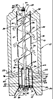
Figure 1 illustrates in schematic, partial
longitudinal section a sub-assembly for dust suppression
and lubricating drill bits which is mountable in a drill
string behind the drill bit head. The sub-assembly
comprises an outer cylindrical housing 10 which has at
its lower portion 20 a tapered rotary connection 12
adapted to receive the threaded rotary shoulder
connection 15 of a drill bit 14 illustrated in Figure 2.
This detachable connection is of conventional nature and
known in the field; it will not be described any further.
The sub-assembly also comprises a cylindrical inner
housing 16 which is coaxial with the outer housing 10 but
of lesser radius so as to create an annular chamber 18
between the inner housing 16 and the outer housing 10.
Around the periphery of the outer housing 10 and towards
the lower housing end 20, which in use receives the drill
bit 14 and has a greater wall thickness than the upper
part,, are provided a series of radially extending through
holes 22. The inner housing 16 has arranged therein a
tight-fitting spiral flange 24 supported on a hollow
central rod or tube 26 which is arranged coaxially with
the inner and outer housings 16, 10. The spiral flange
24 extends between an axial inlet opening 28 on the upper
terminal end of the inner housing 16 and ends with
distance from an exhaust opening 30 in the lower terminal
end of the inner housing 16. The spiral flange 24
provides a centrifugal raceway for an air-liquid mixture
fed into the sub-assembly as will be described
hereinafter. A second spiral raceway 32 having only
about one 180 turn is arranged 180 angularly spaced
apart~from the first spiral raceway 24 such as to provide
a second short initial centrifugal raceway for the air-
liquid mixture to be conveyed and separated in the dust
suppression sub-assembly as described below.
CA 02201038 2005-07-29
- 9 -
The inner housing 16 is provided with a plurality of
slots 34 in its wall located 180 angularly spaced apart
and along the length of the inner housing 16 such as to
be located adjacent the points where the spiral flange or
raceway 24 abuts against the inner surface of the inner
housing 16.
In operation of the dust suppression sub-assembly
connected to a rock drill bit, water and air enter
through the inlet opening 28 into the inner housing 16
from the drill string connected at the top end of the
sub-assembly (not shown), and flow along the spiral
raceways 32 and 24. The water is forced gradually
outwards by the centrifugal action of its motion along
the downward path on the spiral and exits, as shown by
arrows 38, through the plurality of slots 34 along the
length of the inner housing 16 into the chamber 18
between the inner housing 16 and the outer housing 10.
As would be evident to a skilled person in the art, the
water. is progressively removed from the in-coming air-
water stream as it progresses in downward direction along
the spiral raceway 24. The edges of the slots 34 may be
shaped with a trailing edge in the direction of travel of
the water so as to be curved inwards to act as deflectors
or scrapers to scrap the water from the inner walls of
the inner housing 16 and direct the water radially
outwards.
Due to the differences in mass, substantially only
air as indicated by arrows 36 passes the lower terminal
end of the spiral raceway 24 and exits the inner housing
16 as indicated by arrows 39 through a plurality of
axially extending, equidistantly spaced apart bores 42
provi'ded in an annular support bush 40 mounted at the
terminal end of the inner housing 16. The air continues
down into the interior of the shouldered connection 14 of
the drill bit 16 illustrated in Figure 2.
On the other hand, the water expelled through the
radial slots 34 continues to move outwards under the
effect of centrifugal forces, which results in a further
CA 02201038 2005-07-29
- 10 -
separation of water and any entrained air. The water
gathers at the inward facing surface of the outer housing
while the air tends to gather towards the outer
surface of the inner housing 16. The water separated by
5 this action travels down the inward facing surface of the
outer housing 10 where it exits the dust-suppression sub-
assembly through the radially extending holes 22 at the
base of taper boss 44.
In use, the radial holes 22 spray the expelled water
10 onto the debris forced up the bore hole by the
pressurised air exiting from the drill bit 14 in a manner
to be described more fully below. The pressure in the
volume space between the inner and outer housings 16, 10
is positive with respect to the outside of the outer
housing 10 received in the bore hole and provides
positive pressure to eject the water through the radial
holes 22. The size and number of radial bores 22 depends
on the volume of water to be dispersed and on the desire
to avoid excessive pressure loss in the upward travelling
debris.
The air gathered near the outside surface of the
inner housing 16 is free to re-enter the inner housing 16
through the water dispersing slots 34.
Arranged within the lower part 20 of the dust-
suppression sub-assembly is a sub-assembly for
lubricating the rock drill bit 14 as indicated generally
at 60. The lubricating sub-assembly 60 comprises a
cylindrical tube section 62 fixed at its upper terminal
end to the lower terminal end of the central supporting
rod 26 of the spiral raceway 24 through an annular
retention bush 63 which is preferably fitted into the
tube section 62 and which is fixed onto the lower
terminal end of rod 26. The lower terminal end of tube
section 62 is fixed within above-mentioned annular
support bush 40, so that the tube section 62 extends
coaxially within the lower part of the inner housing 16
and is axially fixed with respect thereto.
CA 02201038 2005-07-29
- 11 -
The lubricating sub-assembly further comprises a
pneumatically activated one-way valve assembly arranged
to dispense predetermined quantities of a lubricant from
the lubricating sub-assembly. In the illustrated
embodiment of Figure 1, the one-way valve includes a
poppet-type hollow actuator rod or plunger tube 64 which
is arranged coaxially within the tube section 62 and
extends within the hollow supporting rod 26 and protrudes
from the terminal upward end of the dust-suppression sub-
assembly as can be seen at the top of Figure 1. The
plunger tube 64 is arranged to reciprocate within hollow
rod 26 and tube section 62 against the biasing force of a
spring 66 arranged between an upper collar 68 of the tube
26 and an actuator head section 70 connected to the upper
terminal end of the plunger tube 64. A screw 72 is
removably secured into the upper terminal end of the
actuator head section body 70 and provides a means for
filling up the hollow plunger tube 64 with lubricant.
The terminal lower end of the hollow plunger tube 64 is
closed and only a dispensing orifice 74 is arranged in
the circumferential wall near the bottom end of the
plunger tube 64 as will be described herein below. At
least- two oil balance holes, one of which is indicated at
65 are provided in the circumferential wall of the
plunger tube 64 such that lubricant filled into the
plunger tube can ingress into the chamber 76 formed
between the inner surfaces 77 of the tube section 62, the
outer surface 78 of the plunger tube 64, the downward
facing surface 79 of the retention bush 64 and an annular
sealing bush 80 fitted into the lower end to close tube
section 62 and which has an axially extending bore with
an inner diameter adapted to receive the lower terminal
end of the plunger tube 64 with a fit preventing leakage
of lubricant contained in chamber 76 past the annular
seal surface 82 facing the lower terminal circumferential
surface of plunger tube 64.
The plunger tube 64 may have an outer diameter to
correspond with the inner diameter of the raceway
CA 02201038 2005-07-29
- 12 -
supporting rod 26 or be smaller such as to form an
annular chamber also within the supporting rod 26. In
such case, the upper terminal end of the raceway support
tube 26 has to be sealed with respect to the upper end of
plunger tube 64. Thus, the interior of plunger tube 64,
the optional annular chamber defined between the inner
surface of the raceway support tube 26 and the exterior
surface of the plunger tube 64 and the chamber defined
within the tube section 62 provide a predetermined volume
which is fillable with lubricant for lubricating the
bearings of the drill bit attached to the sub-assembly.
It should be noted that the spring constant of
spring 66 and the shape of the actuator body 70 are to be
dimensioned such that they maintain the dispensing
orifice 74 at the lower end of plunger tube 64 facing the
seal surface 82 when in a deactivated position of the
valve and such as to move the plunger tube 64 in downward
direction thereby shifting the dispensing orifice 74 into
the widened inner diameter bore 84 of sealing bush 80
upon positive air pressure of predetermined value being
applied at the actuator head section 70 of the plunger
tube 64. It should be appreciated that the profile of
the inside surface of the central axial bore through the
sealing bush 80 can be chosen and adapted to provide a
desired lubricant flow rate out of dispensing orifice 74
into the widened inner diameter bore section 84. Of
course, other types of seal seats can be implemented, for
example, where the plunger tube 64 is a (non-hollow)
plunger rod and the actual dispensing orifice would be
provided on the seating bore surface of the seal bush 80
itself, and a predetermined upward movement of the
plunger rod would be required to dispense lubricant
through said orifice. Different types of valve seats and
valve plungers may be used instead of the illustrated one
and are readily available to the skilled person. A
preferred form of a pressurising valve assembly is
discussed below in connection with Fig. 5.
CA 02201038 2005-07-29
- 13 -
The lubricating sub-assembly further includes a
communicating adaptor 100 illustrated in Figures 3 and 4.
The adaptor is used to provide fluid communication
between the central bore 84 of sealing bush 80 on one
side and air circulation passages 92 to leading the
bearings 90 for the bit cones 94 supported on the bit
body 96 of the drill bit 14 illustrated in Figure 2 on
the other side. The adaptor 100 comprises a circular
plate member 102 having, in the illustrated embodiment,
seven equidistantly spaced apart axial through holes 104
spaced radially from and surrounding a connecting tube
106 welded into a cylindrical sack hole on the upper
surface of support plate 102. Three inclined mounting
bores, 108 extend through the central region of support
plate 102 between the upper and lower surfaces such as to
communicate the interior of connecting tube 106 with the
lower side of support plate 102. Within each mounting
hole 108 is fixedly received a communication tube 110
extending in downward direction from the supporting plate
102 with a defined angle of inclination. The adaptor
assembly 100 is received within the threaded rotary
connection neck 15 of the drill bit body (see also Fig.
2). To this end, a stepped recess is machined on the
inside of the rotary connection neck 15 as is
schematically illustrated in Figure 3. Once mounted,
the adaptor assembly 100 is fixed against rotation and
axial, movement either by welding or appropriate retention
means such. as a key and circlip assembly. The adaptor
100 is arranged within the connection collar 15 of the
drill bit 14 such that the three communication tubes 110
are connected to a respective tubular connection
interface member 112 which itself communicates with the
air circulation passages 92 provided in the body 96 of
the drill bit 14 (see Fig. 2) . The air circulation
passages 92 are in communication with the different
bearings 90 supporting the rotary drill cones 94 on the
legs of the drill bit body 96. The layout of such drill
CA 02201038 2005-07-29
- 14 -
bit 14 is conventional and will not be described in any
further detail.
Thus, the adaptor assembly 100 provides a leak-free
communication path from the interior of connecting tube
106 of the lubricating sub-assembly 60 to the bearings 90
housed in the drill bit body 96 via the communication
tubes 110 and air circulation passages 92. The
connecting tube 106 has such dimensions as to be received
with a tight, leak-free fit within the bore 84 of the
sealing bush 80 in the lower part 20 of the outer housing
10 when the threaded rotary shouldered connection 15 is
threaded into the correspondingly threaded connector
section 12 of the sub-assembly. Thus, fluid
communication is provided between the lubricant filled
cavities of the lubricating-sub-assembly 60 (the adaptor
assembly 90 forming part thereof) and the air circulating
passages 92 leading to the bearings 90 of the drill bit
14. Fluid communication can be regulated or completely
shut-off by the plunger tube 64 of the one-way valve
assembly which thus acts as a backflow valve for
supplying predetermined lubricant amounts to the bearings
of the drill bit.
Turning now to Fig. 5, there is illustrated a second
embodiment of the lubricating sub-assembly, generally
indicated at 60. Apart from the differences noted below,
the sub-assembly is similar to the one described with
reference to Fig. 1, and the same reference numerals will
be used to denote same as functionally similar parts and
element.
As described above with reference to Fig. 1, the
lubricating sub-assembly 60 is mounted within the lower
part , 20 of the dust suppression sub-assembly and
comprises a cylindrical tube section 62 fixed at its
upper terminal end to a component of the dust sub-
assembly. The interior of the tube section 62 provides
the lubricant filled chamber 76. The annular support
bush of the embodiment of Fig. 1 which supports the lower
end of tube section 62 within the inner cylindrical
CA 02201038 2005-07-29
- 15 -
housing 16 of the dust suppression sub-assembly is
replaced by non-illustrated radially extending web
members, which center tube section 62 to extend coaxially
within the inner housing 16, and by a displaceable
annular plate 41 which closes the lower terminal annulus
between tube section 62 and the cylindrical inner housing
16. Annular plate 41 is supported in a position in
which it abuts on the lower terminal end of inner housing
16 by a coil-spring 43 with small spring coefficient
which itself is supported on a ledge formed in the
internal cavity of the lower part 20 of the outer housing
10. The inner edge of the annular plate 41 is guided
along a short length of seat member 80' - (which will be
described later in more detail) which closes the lower
end of tube section 62. The coil spring 43 and annular
plate 41 thus form an airlock which is opened when
positive air pressure is applied to the dust suppression
assembly as described above, thereby allowing air passage
as indicated by arrow 39a once depressed and prevents
backflow of any fluids into the dust suppression sub-
assembly when the drill bit is being driven too hard into
the bore head surface as occasionally happens.
As previously described with reference to Fig. 1, a
pneumatically activated one-way valve assembly is
arranged to dispense a metered quantity of the lubricant
which is received within holding chamber of tube section
62. In the embodiment illustrated in Fig. 5, the one-
way valve includes a poppet-type hollow or solid
actuating rod 64' which is arranged coaxially within the
tube section 62 for reciprocating movement and which is
operated in the manner previously described above with
reference to Fig. 1. The illustrated lower part of the
actuating rod 64' is subdivided into a first, upper
section 64a of greater diameter than a second, lower end
section 64b, so that an annular shoulder 64c is formed
between the two sections 64a, 64b and which provides a
displacement piston surface.
CA 02201038 2005-07-29
- 16 -
The seal bush or seat member 80' is fixedly fitted
into the lower end to close tube section 62 and comprises
an upper cylindrical boss portion 80b which mounts tube
section 62, and a lower cylindrical connection collar
80a. A bore 82a which provides the cylindrical sealing
surface 82 extends axially through the boss portion 80b
and has an inner diameter adapted to receive the lower
terminal rod end 64b with a fit allowing movement of the
rod within the bore 82a but preventing leakage of
lubricant from chamber 76 to a substantial extent past
the annular seal surface 82 on which the circumferential
surface of the lower rod end 64b abuts. Bore 82a ends
in a dispensing bore 84 of greater diameter which is
formed in collar 80a of the sealing bush 80'. As will
be further noted from Figure 5, an axially extending
dispensing channel or slit 74' is machined into the outer
peripheral surface of lower end rod section 64b to extend
from the shoulder 64c close to the terminal end of the
rod 64'.
In upward extension of the boss portion 80b of
sealing bush 80' and integral therewith is formed a
pressurisation cylinder 81 which has an inner diameter
which corresponds to the outer diameter of upper rod
secti-on 64a. The latter can be immersed into the
pressurisation cylinder 81 so that the piston surface 64c
pressurises the lubricant amount which is received
therein so as to dispense the metered lubricant under
pressure upon the actuating rod 64' being moved in
downward direction and the dispensing channel 74'
reaching a position in which it is in fluid communication
with the dispensing bore 84. This is achieved when
positive air pressure of predetermined value is applied
at the upper, non-illustrated actuator rod head section
as previously described. A backflow valve 67 is
arranged to provide fluid communication between the
interior of the pressurisation cylinder 81 and the
lubri'cant chamber 76 to allow lubricant ingress when
plunger rod 64' is moved in upward direction after the
CA 02201038 2005-07-29
- 17 -
lubricant dispensing operation is finalised. Thus, the
metered amount of lubricant contained in the
pressurisation cylinder 81 is dispensed to lubricate the
bearings for the drill bit cones supported on the drill
bit body as previously described with reference to Fig.
2.
As can be further seen in Figure 5, the cylindrical
collar 80a of sealing bush 80' receives therein in fluid
tight fit the connecting tube 106 of the communicating
adaptor 100 which is mounted in the threaded rotary
shoulder connection 15 of the drill bit, so that
lubricant entering the dispensing bore 84 is injected
into the communicating tubes 110 which lead to the air
circulation passages provided in the body of the drill
bit (see previous description).
In further modification of the embodiment
illustrated in Fig. 1, cooling air is branched off the
air supply chamber 18 of the dust suppression assembly
into dispensing bore 84 to be supplied as indicated by
arrow 39b together with the metered lubricant to the
bearings of the drill bit. To this end, a total of 4-
inclined air passage bores 81 extend from the outer
peripheral surface of the bores section 85b of the bush
80' dispensing bore 84 of sealing bush 80'. The lower
end of tube section 62 is heretofore provided with 4
bores which align with the corresponding openings of the
air passage bores 81.
The lubricant amount which will be dispensed from
the pressurisation cylinder 81 and the pressurisation
degree will depend on the geometry of the cylinder 81,
the displacement stroke length of piston surface 64c,
diameters of rod sections 64a, 64b and dimensions and
location of dispensing channel 74', of which more than
one can be provided.
In operation of the combined dust suppression and
lubri-cating sub-assembly as illustrated in Fig. 1 or Fig.
5, debris created by action of the drill bit are driven
upwards from the drill bit along the bore hole by the air
CA 02201038 2005-07-29
- 18 -
jettisoned through a jet nozzle 93 arranged in the cavity
dome 95 between the individual bit cones 94 of the drill
bit 14. Upon the debris-air mixture reaching the region
of the radial holes 22 in the outer housing of the dust
suppression sub-assembly area, it is wetted, the air then
carrying the resultant slurry up the bore hole. The dust
suppression sub-assembly ensures that little air remains
in the debris extraction water compared to that initially
fed through the mouth 28 of the inner housing 16 of the
sub-assembly at the beginning of the spiral raceway.
Accordingly, essentially dry air (90%-98% air) is
delivered to the drill bit; the drill bit cones 94 are
therefore subject to the blast of air only, rather than a
thick slurry of water, air and debris which rapidly wears
the drill bit and its bearings. Also, the essentially
dry air reaches through appropriately spaced air
circulation passages within the bit body the different
bearings of the cone bits thus effectively cooling the
bearings. These air circulation passages are preferably
additional to those to which the communication tubes 110
are connected; otherwise, the tubular interface members
112 have to be of a type which also admit air, apart from
lubricant. The substantial absence of water from the air
received within the drill bit body ensures minimal water
induced corrosion of the bearings. Furthermore, the
lubricant sub-assembly 60 provides a predetermined
lubricant amount from the lubricant chamber of the sub-
assembly upon actuation of the one-way valve assembly
through the adaptor assembly via its communication tubes
and the air circulation passages within the body of the
drill bit to the bearings, thereby substantially reducing
frictional wear and enhancing corrosion protection.
It is self-evident that the lubricating sub-assembly
can be provided as a separate, self-contained modular
section which can be connected between the drill bit and
the dust suppression sub-assembly, or to the stabiliser,
in absence of use of a sub-assembly for dust suppression.
As illustrated, the lubricating sub-assembly can be
CA 02201038 2005-07-29
- 19 -
built into the dust suppression sub-assembly or even the
stabiliser.
The inventive concept has been described with
reference to particular embodiments and it should be
appreciated that it may be embodied in other ways. For
instance, the dispensing valve assembly may be different
and not necessarily be actuated only upon positive air
pressure being applied through the drill string to the
drill bit. The size of the tube section 62 may be
adapted to hold a predetermined lubricant volume
therefore avoiding the need of re-filling the lubricating
sub-assembly prior to a time at which the drill bit cones
have to be replaced due to normal wear of the working or
cutting surfaces thereof. Furthermore, it will be
appreciated that the tube section 62 could be omitted all
together in case the available volume within the hollow
plunger tube is big enough to hold a sizeable quantity of
lubricant. Alternatively, and as indicated above, the
plunger tube may not be hollow as in the embodiment of
Fig. 1, therefore requiring a modified actuation and
dispensing mechanism wherein the plunger rod closes a
dispensing, orifice in the seat member or bush 80 as
illustrated in Fig. 5; the plunger is then moved in a
controlled manner in upward direction to allow passage of
predetermined quantities of lubricant from the chamber
within the tube section into the dispensing bore.
With a lubricating sub-assembly in accordance with
the present invention mounted in a drill string, a
considerable increase in consumable bit life is achieved
by way of preventing water corrosion of the bearings of
the drill bit and enhacing bearing lubrication. It is to
be understood that the lubricating oil can also be
directed to other friction surfaces and it is equally
evident that a lubricating sub-assembly can be
incorporated in a drill string using hammer drills
instead of the illustrated roller bit drill.
Providing a direct lubrication of the bearings and
friction surfaces on the drill bit by way of a
CA 02201038 2005-07-29
- 20 -
lubricating sub-assembly in accordance with the present
invention substantially increases life expectancy and
reduces otherwise high wastage of lubricants in the
presently carried out method of admixing soluble oil with
the water used for dust suppression or injecting oil
directly into the main airline. Lubricant storage inside
the specially devised sub-assembly, which can easily be
retrofitted into existing drill strings, enables direct
application of lubricant to the bearings and wear
surfaces with no loss of lubricant. It is expected that
bearing life will increase by at least a factor of four
(4) as compared to conventional assemblies and methods of
operation of drill bits. Advantageously, the lubricant
holding chambers of the lubricating sub-assembly can be
dimensioned such as to hold enough lubricant to enable
the drill bit to be operated to last 10,000 metres
drilling length before replacement or repair of the drill
bit cones due to frictional wear of cutting surfaces
becomes necessary, since only small amounts of lubricant
are riecessary to reduce friction and enhance bearing life
to such an extent that life expectancy of the bearings is
higher than the cutting surfaces of the drill.