Note: Descriptions are shown in the official language in which they were submitted.
;~ ~, ~ ~; 1
L ~ i1~ i (j i t
WO 96/10733 PCT/NL95/00335
Title: Flow sensor
The invention relates to a flow sensor, in particular
suitable for use in air flow measuring, comprising an impeller
suspended for free rotation in a tube section.
With known flow sensors of the above-mentioned type, a
fan impeller is for instance used as impeller, arranged in a
tube section so as to be freely rotatable therein. The
rotations of the impeller are measured, whereupon the flow
rate through the tube section is determined with some
precision. With the known flow sensors, the relation between a
measured speed and the flow rate through the tube section is
not linear and moreover depends on the pressure drop over the
measuring system. In particular at low speeds and small flow
rates, and at great pressure differences over the tube
section, a highly deviant behavior may be created.
A fan impeller is designed so that a rotation energy
can thereby be converted into an air movement. The number of
blades and the blade configuration of the fan impeller are
selected to that end. When such a fan impeller is employed as
a freely rotating fan impeller, i.e. a fan impeller not driven
by means of a motor or a like means, the relation between the
rotary speed and the flow rates through the surface covered by
the impeller will deviate substantially from a linear
relation, in particular at low speeds and/or great pressure
differences between the two sides of the impeller, and will
moreover be directly dependent on the pressure difference over
the tube section.
At low speeds and great pressure differences, air will
be led back through the impeller, the so-called back-flow,
which causes the rotary speed of the impeller to be changed at
a constant flow rate, for instance as a result of an
adjacently disposed ventilating fan. Moreover, a fan impeller
typically causes strong air turbulences, which also causes the
action of the flow sensor to be adversely affected. This means
that such flow sensors have a poor measuring characteristic,
in particular at low flow rates, and that these known flow
sensors are in particular not pressure-independent.
!'
n ~.
WO 96/10733 ~ ' "' ' ~'' r ~ PGT/NL95/00335
2
The object of the invention is to provide a flow
sensor of the type described in the opening paragraph, wherein
the drawbacks mentioned are avoided while the advantages are
maintained. To that end, the flow sensor according to the
invention is characterized by the features of claim 1.
The blade angles of the different cross sections of
the blades of the impeller of the flow sensor according to the
invention provide a flow sensor having an almost pressure-
independent measuring characteristic within the measuring
range of the flow sensor. The calibration combination to be
referred to as design couple, consisting of a calibration flow
rate and a calibration speed can be selected so that this
measuring characteristic can readily be adapted to the
measuring means and further means, if any, for the processing
of the registered speeds of the impeller during use. The
characteristic, given according to the invention, of the curve
of the blade angles over the blades of the impeller offers the
advantage that, starting from a design couple suitable for the
desired use and from a suitable tube section diameter, a
substantially pressure-independent flow sensor can always be
obtained, i.e. for any application a flow sensor can be
designed having a substantially linear measuring
characteristic, which measuring characteristic comprises at
least the design couple selected. Owing to its construction,
in particular in combination with a suitable material
selection, the flow sensor is suitable for use in dusty and
corrosive environments, at strongly varying temperatures and
at different humidities. The flow sensor can be used for gas
flow measurement, but is also suitable for use in fluid flow
measurement.
A flow sensor according to the invention is in
particular suitable for use in industrial, agricultural and
civil utilizations in respect of air conditioning, process
control, emission control, emission measurement in practical
circumstances and the like.
A further elaboration of the flow sensor according to
the invention is characterized by the features of claim 2.
r: ~
22 ~.~ ~ o ~r 1
WO 96/10733 PCT/NL95/00335
3
V~lhen a flow sensor with a freely-rotating impeller is
used, it is important that the speed of the impeller during
use remains within given limits at a minimum and maximum flow
rate to be measured, so as to preclude disturbances of the
measuring characteristic. At unduly high speeds, movements of
the blades will result in an erratic behavior of the impeller,
which adversely affects the measuring precision and the
sensitivity. Moreover, at unduly high speeds of the impeller,
unacceptable noise production and wear occur. At unduly low
speeds, the measuring precision of the flow sensor becomes too
low.
In order to obtain a better measuring behavior of the
flow sensor within the desired measuring range, the flow
sensor is preferably characterized by the features of claim 3.
In a particularly advantageous embodiment, the flow
sensor according to the invention is characterized by the
features of claims 4 and 5.
By providing the impeller with two, preferably
diametrically opposite blades, a stable impeller is obtained
which can be bearing-mounted in a simple manner, because only
minimum forces are exerted on the bearing. After all, unlike
the impeller of the known flow sensors, the impeller according
to the invention is not designed for the transfer of energy.
Only the friction of the bearing needs to be overcome.
Moreover, only a very small part of the frontal surface of the
tube section is covered by a stationary impeller. Owing to
these measures, the flow resistance, and accordingly the
impact of the impeller on the flow pattern in the tube section
are minimal. Because the blades extend to adjacent the inner
wall of the tube section, the entire tube section is covered
a during one revolution of the impeller. With the impeller
according to the invention, this has the advantage of
p rendering the motional pattern thereof independent of the flow
pattern in the tube section. The flow sensor according to the
invention can be used with both turbulent and laminar flow in
the tube section without affecting the measuring
L ~./ i ~ 'l
WO 96/10733 PCT/NL95/00335
4
characteristic, while in each case, the flow sensor keeps
functioning accurately.
In an alternative embodiment, the flow sensor is
characterized by the features of claim 9.
By disposing a ventilating fan in the tube section, a
compact device is obtained which can easily be installed,
while the impeller and the ventilating fan can be adjusted to
each other in an optimum manner. Arrangement of the
ventilating fan downstream of the impeller results in a high
accuracy of the flow sensor.
In this connection, it is particularly advantageous if
the flow sensor is also characterized by the features of
claim 10.
The opposite directions of rotation of the ventilating
fan and the impeller produces an advantageous flow pattern
within the tube section, which prevents disadvantageous
disturbances of the measuring characteristic, for instance
caused by undesired vibrations.
The invention further relates to an impeller of the
type set forth in the preamble of claim 14, which impeller
according to the invention is characterized by the features of
the characterizing part of claim 14.
Such an impeller can particularly advantageously be
arranged within a tube section and is then suitable for use
with a flow sensor, because it has substantially a pressure-
independent rotation characteristic. The impeller can easily
be adapted to the diameter of a suitable tube section, in such
a manner that at one rotation of the impeller within the tube
section, substantially the entire cross section of that tube
section is covered by the blades.
The invention moreover relates to a ventilating
device, in particular suitable for use for the ventilation of
spaces, and to a method for the manufacture of a flow sensor,
comprising a freely-rotating impeller disposed in a tube
section.
To explain the invention, exemplary embodiments of a
flow sensor and a ventilating device will hereinafter be
~~~,~ ~ ~..:~t i
WO 96/10733 PCT/NL95/00335
described with reference to the accompanying drawings,
wherein:
Fig. 1 is a sectional view of a stable comprising a
ventilating device;
5 Fig. 2 is a partially sectional side elevation of a
flow sensor according to the invention;
Fig. 3 is a sectional view of an impeller taken on the
line III-III in Fig. 2;
Fig. 4 schematically shows the bottom side of a blade
cross section according to Fig. 3; and
Fig. 5 is a front view of an impeller.
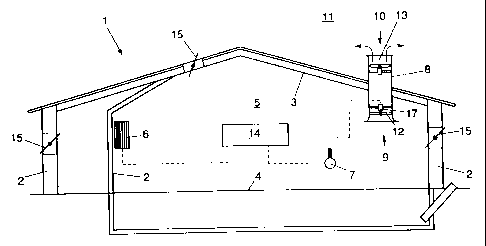
Fig. 1 shows a stable 1 comprising an inner space 5
defined by a number of walls 2, a roof 3 and a floor 4.
Provided in the inner space 5 are heating means 6 and
measuring means 7 for determining the composition of the air
in the inner space 5. Provided in the roof 3 is a tube section
8 communicating by a first open end 9 with the inner space 5
and connecting by the opposite, second open end 10 to the
outer space 11 of the stable 1. In the tube section 8, which
has a circular inner section, an impeller 12 is freely
rotatably suspended adjacent the inwardly facing first open
end 9, which impeller 12 will be further discussed
hereinafter. Adjacent the second open end 10, a ventilating
fan 13 is disposed in the tube section, by means of which
ventilating fan air can be discharged from the inner space 5
to the outer space 11 via the tube section 8.
The heating means 6, the air composition-measuring
means 7, the impeller 12 and the ventilating fan 13 are all
connected to a control unit 14, for instance a computer-
controlled regulating unit. Also connected to the regulating
unit 14 are controlled ventilation-regulating valves 15 in the
walls 2, the roof 3 and/or the floor 4. On the basis of the
air composition measured, the ventilation-regulating valves 15
are controlled into the open and closed positions, the
ventilating fan 13 being controlled in such a manner that a
desired air flow, necessary for freshening the air in the
inner space 5, is discharged through the tube section 8. In
~ ,-. .; / r; ,
WO 96/10733 ~ ~- ''% ' ~> 'T ~ PCT/NL95/00335
6
this connection, it is important that the air flow discharged
is accurately determined and regulated to obtain an optimum
ventilation of the inner space 5, without for instance wasting
unduly much heat and without causing draft.
The impeller 12 comprises two blades 16, disposed
diametrically opposite each other and attached to a core 30
which is bearing-mounted in a housing 32 so as to be smooth-
running, which housing is centrally suspended within the tube
section by means of a number of radial spokes 33. The core 30
has a small frontal surface and is aerodynamically shaped, so
that the flow pattern of the air within the tube section 8 is
minimally affected by the core 30. The axis of rotation S of
the impeller 12 coincides with the longitudinal axis of the
tube section 8. The blades 16 extend to near the inner wall of
the tube section 8. The distance between the inner wall of the
tube section 8 and the free end of the blade 16 is less than
2~ of the diameter of the tube section, and is preferably
approximately 1~. Accordingly, almost the entire cross section
of the tube section is covered by the blades 16 during use,
enabling the flow sensor to be used both in the case of
turbulent flow and in the case of laminar flow in the tube
section. Preferably, the direction of rotation of the impeller
is opposite to the direction of rotation of the ventilating
fan.
In the embodiment shown, the tube section is at its
first open end 9 provided with an outwardly bent inflow edge
31 whose curvature radius R is greater than 10~ of the
diameter D of the tube section. The impeller is preferably
disposed either at the level of the inflow edge 31 or at a
distance from the inflow edge 31 which is at least half the
diameter D of the tube section 8. By using of one of these
configurations, influence of the inflow pattern of the air in
the tube section 8 on the measuring characteristic of the flow
sensor is prevented. Further, for that purpose, the impeller
12 and the ventilating fan 13 are spaced apart a distance at
least corresponding to the diameter D of the tube section 8.
~Z .~ ,.' ~, /
1
WO 96/10733 L ~ ~~ ' ~ Li ~ PCT/NL95/00335
7
For measuring the flow rate through the tube section
8, the impeller 12 comprises measuring means 17 for
determining the speed of the impeller 12. The speed measured
is an indication for the flow rate on the basis of which for
instance the rotary speed of the ventilating fan 13 can be
adjusted, the position of the different regulating valves 15
can be accommodated and the heating 6 can be readjusted, by
means of the regulating unit 14.
To enable the flow rate to be calculated from the
speed of the impeller 12 in a cheap and reliable manner, it is
important that there is a linear relation between the flow
rate and the speed measured, regardless of pressure
differences between the inner space 5 and the outer space 11
and regardless of the flow pattern within the tube section 8.
This linear relation is substantially determined by the
configuration of the impeller 12, and in particular by the
blade configuration.
For this purpose, to the blades 16 of the impeller 12,
as shown in Fig. 2, it applies that the blade angle H of each
section meets the equation
[tg(H(r)) * Caldeb * C]/[r * D2]= Calrev j1J
wherein
r - distance section relative to the center of the
core (m);
H(r) - blade angle of section at distance r (°);
Caldeb = calibration flow rate (m3/h)
Calrev = calibration speed (rev/min)
D - diameter tube section (m)
wherein C lies between 0.003 and 0.004 and is preferably
6.67/1974. In practice, the blade angle preferably differs
maximally 3° from the optimum blade angle.
The blade angle H is defined as the angle included by
the blade 16 with the axis of rotation S of the impeller 12,
as is shown in Fig. 3.
For calculating the suitable configuration for the
blades 16, a calibration combination K is started from, which
can be referrred to as a design couple suitable for the
rt ~ ~:, f ~ T
WO 96!10733 L ~ " s '~ ~T ~ PCT/NL95/00335
8
application and consists of a calibration flow rate Caldeb and
an associated calibration speed Calrev. The design couple K is
inter alia selected on the basis of the regulating unit 14 and
the speed-measuring means 17 to be used, and forms a point on
the measuring characteristic of the flow sensor. As an
example, Table 1 shows the blade angles of an impeller 12
which is pressure-independent, and hence particularly suitable
for use in a flow sensor according to the invention.
Table 1
Caldeb 500 m3/h Maxdeb 8,000 m3/h
Calrev 125 rev/min Maxrev 2,000 rev/min
D 0.45 m Mindeb 120 m3/h
0.0034 Minrev 30 rev/min
r (m) H (r) () B (m)
0.05 36.8 0.100
0.06 42.0
0.07 46.4
0.08 50.2
0.09 53.4
0.10 56.3 0.061
0.11 58.8
0.12 60.9
0.13 62.8
0.14 64.5
0.15 66.0 0.051
0.16 67.4
0.17 68.6
0.18 69.7
0.19 70.6
0.20 71.5 0.047
0.21 72.4
n, " /
i ;
~ L~ ~ ~~ Lt 1
WO 96/10733 PCT/NL95/00335
9
Subsequently, for a further optimization of the flow
sensor, and in particular the impeller 12, for at least the
larger part of each blade 16, a suitable blade width B is
determined for each section, meeting the equation
[rl*cos (H1) *B1] / [r2*cos (H2) *B2] >1 [ZJ
wherein:
r1 = distance first section relative to the center of
the core (m);
r2 = distance second section relative to the center of
the core (m);
wherein r2 > rl;
H1 = blade angle first section (°);
H2 = blade angle second section (°);
B1 = Blade width first section (m); and
B2 = Blade width second section (m),
wherein to all blade angles of the impeller it applies that
they lie in one quadrant and the the blade angle H and blade
width B have a flowing curve over the blade. For the use of
the impeller in an air flow sensor in a situation as shown in
Fig. 1, the width of the blade should preferably be between 1
and 15 cm. For the embodiment described in Table 1, a blade
width B of 10 cm at a distance of 5 cm is started from. The
curve of the width over the blade is shown in Table 1 in the
right-hand column. In the embodiment shown, the core has a
diameter of approximately 10 cm.
In the case of air flow measurement by means of a freely
rotating impeller, the speed should preferably be kept within
a specific range. Unduly high speeds of the impeller 12
involve a great chance of instability of the blades 16 of the
impeller, which adversely affects the measuring
characteristic. Moreover, this causes substantial wear of the
different components of the device and an unpleasant noise
y level. At unduly low speeds, the measuring accuracy of the
flow sensor is too easily adversely affected.
Given a maximum and minimum allowable speed, a maximum
and minimum measurable flow rate can be determined for each
impeller 12 on the basis of the equations
~_'~~J ~ ~~t I
WO 96110733 PCT/NL95/00335
[ tg ( H ( r ) ~ ) * Maxdeb * C ] / [ r * D2 ] < Maxrev (3 J
and
[ tg ( H ( r ) min ) * Mindeb * C ] / [ r * DZ ] < Minrev (4 J
wherein:
5 H(r)~ = maximum blade angle section at distance r (°);
H(r)min = minimum blade angle section at distance r (°);
Maxdeb = maximum measuring flow rate (m3/h)
Mindeb = minimum measuring flow rate (m3/h)
Maxrev = maximum measuring speed (rev/min)
10 Minrev = minimum measuring speed (rev/min)
By filling in a blade angle H and the maximum
allowable speed in the upper equation (3J, the maximum
measurable flow rate can easily be determined, by filling in
the blade angle H and the minimum allowable speed in the lower
equation (4], the minimum measurable flow rate can easily be
determined.
Conversely, on the basis of the same equations (3J,
(4J, it is also possible to calculate a maximum allowable
blade angle for each section on the basis of the maximum flow
rate to be measured and the maximum allowable speed therefor,
and, likewise, to calculate a minimum blade angle for each
section by filling in a minimum flow rate to be measured and a
minimum speed required therefor. This offers the possibility
of determining, prior to the determination of the blade angles
for an impeller 12, the design limits on the basis of which a
favorable calibration combination K can be selected. Table 2
shows the maximum and minimum blade angle H(r)~, H(r)min for
the different sections for an impeller, starting from the
design criteria given in the heading of Table 2.
WO 96/10733 L L~.. ~"~ i
PCT/NL95/00335
11
Table 2
Maxdeb 6,000 m3/h
Maxrev 2,000 r/min
Mindeb 200 m3/h
Minrev 30 r/min
0.45 m
C 0.0034
radius min. angle max. angle
m (°) (°)
0.05 24.2 45
0.06 28.3 50.2
0.07 32.2 54.4
0.08 35.7 58
0.09 39 60.9
0.10 42 63.4
0.11 44.7 65.5
0.12 47.2 67.4
0 .13 49.4 68'.
9
0.14 51.5 70.3
0.15 53.4 71.5
0.16 55.2 72.6
0.17 56.8 73.6
0.18 58.3 74.5
0.19 59.7 75.2
0.20 60.9 76
0.21 62.1 76.6
0.22 63.2 77.2
0.23 64.2 77.7
0.24 65.1 78.2
0.25 66 78.7
0.26 66.8 79.1
0.27 67.6 79.5
0.28 68.3 79.9
,,?", ; 'L" 1
R'O 96/10733 L ~ " ' ~~ r PCTINL95I00335
12
When a design couple K has been selected, the optimum
blade angles H can be determined by filling in the first
equation [1J. If it appears that the blade angles H found lie
too much outside the limit values found with the third and
fourth equations f3], (4J, an adjusted design couple K can be
selected. In this manner, the curve of the blade angles can
easily be optimized. Next, for each blade section the width
can be determined on the basis of the second equation [2], in
such a manner that the blade configuration meets the
requirements set and is hence pressure-independent and
provides a desired, linear measuring characteristic of a
suitable accuracy.
Fig. 3 shows a cross section of a blade 16 of an
impeller 12. The blade 16 has a front side 18, a rear side 19,
a leading side 20 and a bent top side 21. In the embodiment
shown, the leading side 20 is substantially flat, which has a
positive influence on the pressure-independence of the
impeller. The curvature of the blade, given by the difference
between the inflow angle f~l and the outflow angle t32, as shown
in Fig. 4, is less than 5°, and preferably about 0°. The
maximum thickness of the blade is about 10~ of the blade
width, and is located at about 1/3 of the blade width,
measured from the front side 18 of the blade 16. The blade
angle H corresponds to the average of the inflow angle f31 and
the outf low angle f~2 .
Fig. 5 shows an impeller 40 suitable for use in a flow
sensor which is pressure-independent. The blade angles H1, HZ
of two sections at different distances rl, r2 from the core 30
meet the equation
(r2/rl) *tan(H1)=tan(H2) [5]
wherein
rl = distance first section relative to the center of
the core (m);
r2 = distance second section relative to the center of
the core (m);
H1 = blade angle first section (°);
H2 = blade angle second section (°).
r1 ''1 ~ <, f ,t x
WO 96/10733 1' ~ 'j ~ ~ it ~ PCTlNL95/00335
13
Starting from such an impeller 40, a flow sensor can
be assembled in a simple manner which is almost pressure-
independent. For that purpose, a suitable tube section
diameter D can for instance be determined starting from a
selected blade angle for one of the cross sections of a blade
41 and a suitable design couple K by filling in these values
in the first equation (1]. Then, the length L of the blades 41
can be adjusted to that tube section. When the values found
and a maximum allowable speed are filled in in the second
equation (2], an upper limit for the measuring range of the
flow meter is then given, and, similarly, when the third
equation j3] is filled in, a lower limit is given. Since the
flow sensor has a linear measuring characteristic, it can
readily be determined whether this maximum speed therefor will
actually occur. When this threatens to be exceeded, a
different calibration combination will have to be selected to
which, accordingly, a different diameter of the tube section
will be associated. In this manner, the suitable configuration
of a pressure-independent flow sensor having the desired
measuring range can in each case be obtained, starting from
the impeller 40. Of course, starting from a design couple, it
is also possible to determine for each tube section diameter
the suitable blade angle by filling in the found values in
equation [2].
With a method according to the invention a flow sensor
can be obtained which can be used in, for instance,
agricultural, industrial and civil applications for use in air
conditioning, process control, emission measurement, and the
like. The flow sensor can be used for, for instance, air and
fluid flow measurement in corrosive and dusty environments, at
different temperatures and degrees of humidity.
The flow sensor can be designed for measuring flow
rates of between 200 and 6000 m3/h, but greater and smaller
flow rates are also possible. The blade length of the impeller
can at least vary between 15 and 40 cm, but greater and
smaller blade lengths are also possible. The flow sensor
according to the invention is at least usable at pressure
WO 96/10733 f ~ C ~ ~; ~t j PCT/NL95/00335
14
differences between 0 and 120 Pa, and can achieve a measuring
accuracy of approximately 60 m3/h or less over the selected
measuring range. Of course, the invention is not limited to
the embodiments as shown by way of example. Many variations
are possible within the purview of the invention.
For instance, the impeller may be provided with a
different number of blades and the flow sensor may be used
without ventilating fan, for instance in the case of natural
ventilation. Other sensors may be connected to the regulating
unit, such as for instance mechanical switches and time
switches.
In the regulating unit different regulating programs
may be included, adapted to control a process wherein the flow
sensor is included.
Starting from one of more of the parameters given, the
flow sensor or the impeller according to the invention can in each
case be optimally adjusted to the process to be controlled. In
this connection, the selection of the magnitude of the parameters
is understood to fall within the scope of anyone skilled in the
art.