Note: Descriptions are shown in the official language in which they were submitted.
CA 02201986 2005-03-21
79832-34
1
BRAKE CONTROLhER FOR TRAILER BRAKES
Technical Field
The present invention relates generally to the recreational
vehicle field and, more particularly, to a system and method for
controlling electric brakes on a trailer being towed by a towing
vehicle.
Back~~round of the Invention
Electrical trailer brake control systems for controlling
electric trailer brakes are well known in the art. An example of
one prior art brake control system is the Reese Brakemann II
trailer brake control system presently being commercially
marketed by the assignee of the present invention.
Summary of the Invention
It is a primary object of the present invention to provide a
new and improved brake control system for controlling the brakes
on a trailer being towed by a towing vehicle. Advantageously,
the brake control system may be easily installed and requires
minimum maintenance while providing highly reliable and
dependable operation over a long service life.
Still another object of the present invention is to provide
a trailer brake control system exhibiting greater sensitivity and
enhanced response beyond that presently available with state of
the art brake controllers.
Yet another object of the present invention is~to provide a
CA 02201986 1997-04-07
2
~~smart« brake control system that automatically compensates not
only for changes in the rate of deceleration of the towing
vehicle under braking but also appropriately increases or
decreases the brake amperage control signal as required in
accordance with actual downhill or uphill braking conditions.
Still another object of the present invention is to provide
a new and improved brake control system that is able to sense
lock-up of the trailer brakes and in response thereto
systematically reduces the brake amperage control signal to
reeffect the desired braking performance.
Still another object of the present invention is to provide
a brake control system that eliminates the °hazard light pulsing~t
problem.
Yet an additional object of the present invention is to
provide a brake control system with manual and optional remote
manual overdrive as well as remote operator interface and
feedback subsystems which indicate improper connection of the
brake controller to the electric trailer brakes during
installation and also serve to identify the loss of or
malfunction of brake units during operation.
Additional objects, advantages and other novel features of
the invention will be set forth in part in the description that
follows and in part will become apparent to those skilled in the
art upon examination of the following or may be learned with the
practice of the invention. The objects and advantages of the
invention may be realized and obtained by means of the
instrumentalities and combinations particularly pointed out in
the appended claims.
To achieve the foregoing and other objects, and in
accordance with the purposes of the present invention as
CA 02201986 2005-03-21
79832-34
3
described herein, an improved system is provided for
controlling brakes on a trailer being towed by a towing
vehicle. The brake system includes a means, such as an
accelerometer for sensing the rate of deceleration of the
towing vehicle. Further, the accelerometer may be utilized
to sense inclination of the towing vehicle: that is, the
presence of the towing vehicle traversing an uphill or
downhill grade.
The system also includes a controller, preferably
including a dedicated fuzzy logic microcontroller and an
amplifier for generating the brake amperage output signal to
control the electric trailer brakes. More specifically, the
controller is responsive to inclination and rate of
deceleration control signals received from the accelerometer
and then functions to send a proportionate brake amperage
output signal to control the brakes on the trailer.
Accordingly, a broad aspect of the invention
provides a system for controlling brakes on a trailer being
towed by a towing vehicle, comprising: an accelerometer for
sensing inclination and a rate of deceleration of the towing
vehicle and providing inclination and rate of deceleration
control signals indicative thereof; and a controller
responsive to said inclination and rate of deceleration
control signals received from said accelerometer for sending
a proportionate brake amperage output signal to control the
brakes on the trailer. 4
Still more preferably, the brake control system
also includes a means for sensing the actuation of the
brakes of the towing vehicle and a means for sending a
towing vehicle actuation signal to the controller. The
controller only sends a proportionate brake amperage output
signal to control the brakes of the trailer when both rate
CA 02201986 2005-03-21
79832-34
3a
of deceleration and brake actuation control signals are
received simultaneously by the controller. In the absence
of the brake actuation signal, the controller does not send
a brake amperage output signal to initiate trailer braking.
Accordingly, any possibility of inadvertent trailer braking
in response to sensed deceleration occurring under non
braking conditions, such as when traversing uphill grades,
is eliminated.
The brake control system also includes a means for
manually overriding the system so as to thereby allow a
proportionate
CA 02201986 1997-04-07
4
brake amperage output signal to be produced when desired by the
vehicle operator even in the absence of either or both of the
rate of deceleration and brake actuation control signals. This
may be desirable under certain operating conditions in order to
control trailer sway or where the vehicle operator wishes to
apply the trailer brakes prior to the vehicle brakes.
Still further, the brake control system includes a brake
amperage feedback indicator. Such an indicator may, for example,
include a series of LED lights, a digital gauge or an analog
gauge for indicating the amperage of the brake output signal
being sent to control trailer braking. In this way the operator
is better able to monitor the operation of the system and may
confirm, for example, brake unit loss or malfunction. The system
also allows the operator to visually adjust the braking bias
between the trailer and towing vehicle in accordance with
operator preference and current driving conditions.
Still further, the brake control system includes a
temperature sensor which is connected to the controller to allow
compensation for temperature drift of the accelerometer.
Accordingly, the trailer control system provides consistent
operation under substantially any reasonably anticipatable
climatic conditions.
As an additional convenience feature, the brake control
system may include a means for indicating improper connection of
the system to the brakes on the trailer. Further, a circuit
breaker/fuse may be provided in the wiring circuit for protecting
the system from short circuit in the event of improper connection
to the battery or brakes of the trailer. Accordingly, the
operator installer is warned when improper connection occurs and
the brake control system is simultaneously protected from any
CA 02201986 2005-03-21
79832-34
possibility of damage due to that improper connection.
In accordance with yet another aspect of the
present invention, a method is provided for controlling the
brakes on a trailer being towed by a towing vehicle. The
5 method includes sensing the rate of deceleration of the
towing vehicle and sending a proportionate brake amperage
output signal to control the brakes of the trailer.
Additionally, the method includes sensing the inclination of
the towing vehicle and adjusting the proportionate brake
amperage output signal in accordance with the sensed
inclination. Accordingly, the brake amperage output signal
is increased when the. brakes are applied as the vehicle
traverses downhill grades and reduced when the brakes are
applied as the vehicle traverses uphill grades so as to
provide the desired level of braking force at all times.
In accordance with a further aspect of the method
there is a step of sensing actuation of the towing vehicle
brakes and limiting the sending of the proportionate brake
amperage output signal only to those situations where towing
vehicle brake actuation and rate of towing vehicle
deceleration are sensed and appropriate control signals are
simultaneously received by the controller. Such an
arrangement insures that the trailer brakes are only applied
at appropriate times.
Accordingly, a broad aspect of the invention
provides a method for controlling brakes on a trailer being
towed by a towing vehicle, comprising: sensing rate of
deceleration of one of said towing vehicle and said trailer;
sensing inclination of one of said towing vehicle and said
trailer; generating a variable deceleration signal as a
function of said rate of deceleration and a variable
inclination signal as a function of said sensed inclination;
CA 02201986 2005-03-21
79832-34
5a
sending a brake amperage output signal to control the brakes
of the trailer; and continuously proportioning said brake
amperage output signal in accordance with both said
deceleration and said inclination signal.
Another broad aspect of the invention provides a
method for adjustably controlling brakes on a trailer being
towed by a towing vehicle comprising the steps of: sensing
a deceleration of said towing vehicle; sensing the actuation
of said towing vehicle brakes; forwarding a towing vehicle
brake actuation signal to a controller upon sensing the
deceleration of said vehicle; sensing an inclination of one
of said trailer and said towing vehicles; forwarding a
vehicle inclination signal as a function of said sensed
inclination to said controller upon sensing said
inclination; sending a continuously proportionately adjusted
brake output signal to control the brakes of the trailer
when the brake actuation, the deceleration and the vehicle
inclination signals are received by said controller.
A further broad aspect of the invention provides a
method for controlling brakes on a trailer being towed by a
towing vehicle, comprising: sensing rate of deceleration of
one of the towing vehicle and the trailer; sensing
inclination of one of the towing vehicle and the trailer;
monitoring the sensed rate of inclination; continually
updating and storing the sensed inclination in a memory;
sensing the actuation of said towing vehicle brakes; sending
a brake amperage output signal to control the brakes on the
trailer; and proportioning said brake amperage output signal
in accordance with both said stored sensed inclination and
said deceleration signal.
Still other objects of the present invention will
become apparent to those skilled in this art from the
CA 02201986 2005-03-21
79832-34
5b
following description wherein there is shown and described a
preferred embodiment of this invention, simply by way of
illustration of one of the modes best suited to carry out
the invention. As it will be realized, the invention is
capable of other different embodiments and its several
details are capable of modification in various, obvious
aspects all without departing from the
CA 02201986 1997-04-07
6
invention. Accordingly, the drawings and descriptions will be
regarded as illustrative in nature and not as restrictive.
Brief Description of the Drawing
The accompanying drawing incorporated in and forming a part
of the specification, illustrates several aspects of the present
invention and together with the description serves to eXplain the
principles of the invention. In the drawing:
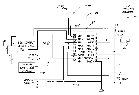
Figures 1 and la are schematics of the system of the present
invention for controlling brakes on a trailer.
Reference will now be made in detail to the present
preferred embodiment of the invention, an example of which is
illustrated in the accompanying drawing.
Detailed Description of the Invention
Reference is now made to Figure 1 showing a schematic of the
brake control system 10 of the present invention. As shown, the
brake control system 10 includes an accelerometer 12 such as an
Analog Devices, Inc. ADX05 Accelerometer having a resolution of 5
g and a microcontroller 14. Advantageously, the accelerometer 12
may be utilized to not only sense the rate of deceleration for
the towing vehicle in which the brake control system 10 is
mounted but also the tilt or inclination of the vehicle: that is
whether the vehicle is traveling uphill or downhill. This may be
done, for example, by processing the lower bandwidth signals from
the accelerometer as tilt or inclination and the higher bandwidth
signals as deceleration. Specifically, the accelerometer 12
monitors tilt so long as no input is received at pin number 15 of
the microcontroller 14. This tilt angle is continually updated
and stored. Once the vehicle brake lights are engaged or the
CA 02201986 1997-04-07
7
manual override switch is depressed, a signal is received at pin
number 15. The signal from the accelerometer at input 16 of the
microcontroller 14 is then processed as a rate of deceleration
and uphill/downhill adjustments in the brake amperage are made in
accordance with the last stored value of the tilt angle.
Preferably, the microcontroller 14 is a fuzzy logic
microcontroller such as an Adaptive Logic AL220PC. As will be
appreciated from the following, the combination of the
accelerometer 12 and microcontroller 14 serves to provide "smart"
braking through the electrical trailer brakes to which the system
10 is connected.
More specifically, the accelerometer 12 provides an
inclination control signal and a rate of deceleration control
signal to the microcontroller 14 that are indicative of the
inclination and rate of deceleration of the towing vehicle. The
microcontroller 14 instantaneously processes this information and
through its operative connection to the amplifier 16 sends a
proportionate brake amperage output signal along the control line
18 to control the brakes on the trailer. The greater the rate of
deceleration of the towing vehicle, the greater the brake
amperage output signal to the trailer brakes in order to apply
greater braking power. The strength of the brake amperage output
signal is, however, modified by the sensed inclination of the
towing vehicle. Accordingly, the normal brake amperage output
signal for level terrain operation is modified and increased when
downhill inclination is sensed and reduced when uphill
inclination is sensed. As a result the system 10 of the present
invention, provides full and effective real time compensation for
road grade conditions.
As should further be appreciated, the system 10 includes
CA 02201986 1997-04-07
8
many additional operating features that significantly enhance the
performance thereof. For example, a temperature sensor 20 is
connected to the controller 14 and functions to compensate for
fluctuations in the sensing capabilities of the accelerometer 12
due to temperature drift.
Additionally, the system 10 includes a means for sensing
actuation of the brakes of the towing vehicle and sending a
towing vehicle brake actuation signal to the controller 14. More
specifically, a wire conductor 22 is connected between the brake
light circuit of the towing vehicle and the controller 14. When
the towing vehicle brakes are engaged, the towing vehicle brake
lights are energized and this electrical signal is carried by the
conductor 22 to the controller 14 thereby giving the controller
an indication of towing vehicle brake engagement. The controller
14 is programmed so as to only provide a brake amperage output
signal along line 18 proportionate to the sensed inclination and
rate of deceleration when the towing vehicle brakes have been
engaged or activated. This eliminates any inadvertent braking
that might otherwise result from the accelerometer providing a
rate of deceleration signal under conditions where braking is not
truly desired (e.g. such as when momentum is lost traversing an
uphill grade).
The system 10 is also equipped with a means of manual
override. More specifically, a manual override switch 24 is
provided. When the manual override switch 24 is activated, the
controller 14 provides a brake amperage output signal to the
trailer brakes along line 18. This feature may be utilized by
the vehicle operator under certain operating conditions including
times when the operator is seeking to control trailer sway.
The system 10 also includes a brake amperage feedback
CA 02201986 1997-04-07
9
indicator for indicating brake amperage to a towing vehicle
operator so that the operator is able to monitor operation of the
system (note feedback line 25 in Figure 1). Preferably, the
brake amperage feedback indicator 26 may take the form of an LED
array as shown in the drawing Figure. It should be appreciated,
however, that a digital or analog gauge could also be utilized.
A switch, knob or other actuator (not shown) may be manually
manipulated by the operator to adjust the strength of the brake
amperage output signal as desired to control trailer
brake/vehicle brake bias or for other purposes. Of course, the
system l0 may also be equipped with a fuse or more preferably a
circuit~breaker to prevent damage to the accelerometer 12 and/or
controller 14 in the event the controller 10 is improperly
connected or wired to the towing vehicle or trailer brake system.
Further, the circuit breaker may be wired so as to close a
circuit to a warning lamp or beeper providing a video or audio
signal indicating improper connection.
In summary, the present system 10 senses towing vehicle
inclination as well as rate of deceleration in order to provide
smart braking. The system 10 compensates for uphill and downhill
operating conditions and sends a proportionate brake amperage
output signal to control the braking force provided by the brakes
of the trailer. The system 10 is also effective to provide
maximum braking power. More specifically, the accelerometer 12
is capable of sensing a decrease in the rate of deceleration when
the brakes lock up. This sensed decrease in the rate of
deceleration causes the microcontroller 14 to step down or reduce
the output from the power amplifier 16: that is, reduce the
brake amperage output signal to the trailer brakes. As a result,
braking force is reduced. This step down reduction in the power
CA 02201986 1997-04-07
output of the amplifier 16 continues until the rate of
deceleration again increases as a result of the wheels with which
the trailer brakes cooperate taking hold on the road surface.
The system 10 also compensates for and eliminates the
problem of hazard light pulsing. More specifically, the
microcontroller 14 is capable of learning the hazard light pulse
pattern of the vehicle and ignoring this input when controlling
trailer braking. Accordingly, it should be appreciated that the
braking system and method of the present invention provide a
10 number of advantages and features unavailable in prior art brake
systems design.
The foregoing description of a preferred embodiment of the
invention has been presented for purposes of illustration and
description. It is not intended to be exhaustive or to limit the
invention to the precise form disclosed. Obvious modifications
or variations are possible in light of the above teachings. The
embodiment was chosen and described to provide the best
illustration of the principles of the invention and its practical
application to thereby enable one of ordinary skill in the art to
utilize the invention in various embodiments and with various
modifications as are suited to the particular use contemplated.
All such modifications and variations are within the scope of the
invention as determined by the appended claims when interpreted
in accordance with the breadth to which they are fairly, legally
and equitably entitled.