Note: Descriptions are shown in the official language in which they were submitted.
CA 02202158 1999-10-21
-1 -
RECLINER CHAIR SEAT ASSEMBLY
AND METHOD O~ UPHOLSTERING
BACKGROUND OF THE INVENTION
1. Field of the Invention
The present invention relates generally to reclining chairs and, more
particularly, to a seat assembly for use in a reclining chair constructed from
pre-assembled modular components and method of upholstering same.
2. Description of Related Art
Recently, an improved method for assembling an article of furniture has been
developed which overcomes the disadvantages traditionally associated with
fabricating, assembling and upholstering reclining-type chairs. The improved
design
incorporates an integrated or "knock-down" construction of the reclining chair
facilitating application of unique fabrication and assembly techniques which
effectively
result in increased production efficiency and cost savings while concomitantly
producing a high-quality article of furniture. In general, the construction of
the
reclining chair is such that the pre-assembled actuation mechanism cannot be
divorced from the pre-upholstered frame components which, when assembled, are
rigidly interconnected to define a "box-like" chair frame or body from which
the pre-
assembled actuation mechanism is integrally suspended. In this manner,. the
conventional construction of supporting the actuation mechanism within a
separate
and distinct mechanism frame assembly is no longer required. The pre-assembled
actuation mechanism includes a drive rod and a front support shaft which are
each
directly supported between left and right upholstered side frame assemblies.
As such,
extremely precise alignment of the actuation mechanism with respect to each of
the
separate upholstered side frame assemblies is possible. Moreover, unique front
and
rear frame rail members interconnect the left and right side frame assemblies
to define
a "unitized" and extremely rigid box-like chair frame or body for inhibiting
side-to-side
flexion of the actuation mechanism suspended therein as well as of the side
frame
assemblies themselves. In addition to the structural and functional advantages
associated with the modular reclining chair of the present invention, a unique
method
~
CA 02202158 1999-10-21
2
of assembling the pre-assembled actuation mechanism as an integrated component
within the frame components is disclosed.
Also included is a leg rest assembly may be operated by the seat
occupant rotating an actuator lever through a limited angel which, in turn,
rotates
the drive rod for selectively extending or retracting a pair of leg rest
pantograph
linkages. The pantograph linkages are uniquely suspended for synchronous
actuation between the drive rod and the front support shaft and protrude
through
apertures provided in the front frame rail member. In addition, an over-
centered
toggle mechanism is provided to assist in extending and retracting the leg
rest
assembly and in retaining the leg rest assembly in its "extended" and "stowed"
positions.
the foregoing reclining chair design and method of making is the
subject of U.S. Patent Nos. 5,222,286 issued June 29, 1993; 5,288,126 issued
February 22, 1994; 5,301,413 issued April 12, 1994; and 5,323,526 issued June
28, 1994 all of which are commonly assigned to the assignee of the present
invention.
SUMMARY OF THE INVENTION
In accordance with the principles of the present invention, an improved
recliner chair seat assembly and method of upholstering is disclosed which is
designed to be readily incorporated into the modular recliner-type chairs
heretofore
described. As a primary object of the present invention, an improved seat
assembly
for a reclining chair which may be positioned lower with respect to the
reclining
chair actuation mechanism is provided. The improved seat assembly can further
be
simply, efficiently and rigidly assembled so as to significantly reduce its
overall
complexity, weight, and cost while providing improved operation and comfort.
It is an additional object of the present invention to provide swing
linkage means which is adapted to permit selective and independent "reclining"
movement of a seat back relative to an improved seat member as well as to
provide
actuation (i.e. protracting and retracting) of a leg rest assembly. The swing
linkage
means is selective positionable with respect to the seat assembly to vary the
amount of vertical displacement of the seat assembly in connection with the
"reclining" movement. As such, the present invention provides a reclining
chair
wherein the minimal force achieved via shifting the weight of the seat
occupant is
utilized as the primary means for moving the seat assembly between an
"upright"
position and a "reclined" position.
CA 02202158 1997-04-08
WO 96/11608 PCT/US95/12795
-3-
It is a further object of the present invention to provide a rocking/reclining
chair
having a front support shaft for connecting the side frame assemblies of the
chair to
form a rigid box-like frame, for supporting the leg rest pantograph assembly,
for
supporting the ratchet sector which selectively inhibits rocking movement of
the chair
and for supporting the seat assembly such that the seat assembly may be
positioned
lower with respect to the rocking/reclining chair actuation mechanism.
It is still another object of the present invention to provide a unique seat
cushion which is secured to the seat frame without staples and therefore can
be
repeatedly installed and removed without affecting the fd and look of the
cushion.
This unique seat cushion, when used in connection with the simpl~ed recliner
chair
and seat frame, facilitates upholstering of the chair.
It is yet a further object of the present invention to provide a front fabric
facia
which is secured to the front frame member of the chair without staples or
other
similar fasteners and therefore can be easily and repeatedly installed and
removed.
Thus, the new front fabric facia, when used in connection with the simplified
recliner
chair frame, also facilitates upholstering of the chair.
Additional objects, advantages, and features of the present invention will
become apparent from the following description and appended claims, taken in
conjunction with the accompanying drawings.
DESCRIPTION OF THE DRAWINGS
Figures 1 A through 1 D are perspective views of an exemplary reclining chair
apparatus shown in various operative positions, the "modular" components of
which
have been fabricated and assembled in accordance with the principles of the
present
invention;
Figure 2 is an exploded front perspective view of a reclining chair of the
type
shown in Figure 1 with upholstery, springs and other parts removed from the
frame
components for illustrating their integrated and interdependent association
with an
improved seat frame construction;
Figure 3 is an opposite perspective view of the reclining chair shown in
Figure 2 with the deletion of the pantograph leg rest, and other actuation
components,
and the addition of upholstery cushions for the seat frame and seat back;
Figure 4 is an exploded view of the front frame rail assembly shown in
Figures 2 and 3;
CA 02202158 1997-04-08
WO 96/11608 PCT/US95/12795
-4-
Figure 5 is a sectional view taken along line 5-5 of Figure 4 having an
installed
upholstered front center panel adapted to be releasably secured to the front
cross
member;
Figure 6 is a sectional view taken along line 6-6 of Figure 4 having an
installed
upholstered front end panel adapted to be releasably secured to the front
cross
member;
Figure 7 is a partial top view of the seat assembly shown in Figures 2 and 3;
Figure 8 is a partial side view of the seat assembly shown in Figures 2 and 3;
Figure 9 is a partial sectional view taken along line 9-9 of Figure 8
illustrating
the rear attachment of the seat frame to the chair frame;
Figure 10 is a partial sectional view taken along line 10-10 of Figure 8
illustrating the front attachment of the seat flame to the chair frame;
Figure 11 is a partial sectional view showing an installed upholstered seat
cushion adapted to be releasably secured to the seat frame of the present
invention;
and
Figure 12A through 12H are various perspective views provided to illustrate
one preferred method for assembling the reclining chair apparatus of the
present
invention.
DETAILED DESCRIPTION OF THE INVENTION
In accordance with the teachings of the present invention, an improved seat
frame construction for use in single and mufti-person articles of furniture
(i.e. chairs
and sofas or loveseats) is disclosed. In addition, the present invention is
also directed
to a method of assembling and upholstering the improved seat frame
construction as
a pre-assembled and "integrated" component of a reclining-type chair or the
like. As
will be described, the pre-assembled seat frame is adapted to be positioned
lower
with respect to the reclining chair actuation mechanism, and likewise, with
respect to
the chair base and the floor. In a preferred embodiment, the seat frame is
assembled
from metal frame members prior to integration into a finished assembled
reclining
chair. Such construction allows for interconnecting the seat frame to the
actuation
CA 02202158 1997-04-08
WO 96/11608 PCT/US95/12795
-5-
mechanism along a vertical surface of the seat frame side members thereby
allowing
the seat frame to be lower in a finished chair.
In the disclosed embodiment, the article of furniture is shown as a
combination
recliner and platform rocker, hereinafter referred to reclining/rocking chair
10, which
includes a pre-assembled actuation mechanism 12 and various upholstered frame
components that can be quickly and simply assembled in a modular fashion as a
seating unit. Such "modular" construction provides a significant advancement
over
conventional furniture fabrication and assembly techniques since manipulation
of
heavy and cumbersome chair frames during upholstery installation is no longer
required. As such, the frame components can be upholstered prior to modular
assembly to actuation mechanism 12 so as to improve individual component
quality
as well as overall system quality and production efficiency. In addition,
selected frame
components, such as the front cross member, seat frame and seat back, can be
adapted to accept upholstered trim panels following modular assembly. For
example,
a seat cushion and an upholstered front trim panel can be adapted to
releaseably
attached to chair 10 after assembly thereof as will be further described
herein.
Moreover, since the seat frame 20 may be positioned lower with respect to the
actuation mechanism 12, recliner chair occupants of varying height will find
the chair
more comfortable and larger removable upholstered cushions may be used.
With particular reference now to the drawings, the functional and structural
aspects of actuation mechanism 12, shown operably suspended from the frame
components of recliner/rocker chair 10, will now be described. More
particularly,
Figure 1 A depicts an exemplary combination reclining/rocking chair 10 having
its seat
assembly 14 shown in a fully "upright" position for permitting a seat occupant
to enjoy
conventional seating. Figure 1 B illustrates reclining/rocking chair 10 in the
"upright"
position with its associated leg rest assembly 16 shown protracted to its
"extended"
position. As seen in Figure 1 C, seat assembly 14 includes a seat back 18
shown in
CA 02202158 1997-04-08
WO 96/11608 PCT/US95/12795
-6-
a "reclined" position relative to a seat frame 20 while leg rest assembly 16
is
positioned in its retracted or "stowed" position. As is known, reclining
movement of
seat assembly 14 is accomplished by the seat occupant deliberately applying
pressure
to seat back 18 such that a seat swing mechanism causes seat frame 20 to move
forwardly and vertically upward for maintaining seating comfort while the
included
angle increases therebetween. Chair 10 may be easily returned to its "upright"
position upon deliberate application of rearward pressure to seat assembly 14
or,
more simply, if the seat occupant leans forward to remove pressure from seat
back
18. Finally, Figure 1 D shows seat assembly 14 of chair 10 in the "reclined"
position
with its respective leg rest assembly 16 protracted to the "extended"
position. In
accordance with the embodiment shown, and as will be described from the
following
disclosure, the entire chair 10 can be easily "rocked" with respect to
stationary base
assembly 22. While the present invention is shown in conjunction with a
reclininglrocking chair as heretofore described, it should be generally
understood that
the simplified seat assembly, upholstery cushions and fabric facias further
detailed
hereafter may be incorporated into a variety of recliner-type chairs, motion
sofa units
and the like.
In accordance with a primary design feature of the present invention, the
various pre-assembled frame components which provide for operably suspending
actuation mechanism 12 within reclining/rocking chair 10 will now be clearly
described.
For purposes of clarity, Figure 2 shows the various pre-assembled frame
components
with their upholstery, padding, springs, etc. removed to better illustrate the
interdependency of the frame components construction which can be rapidly and
rigidly assembled in a relative easy and efficient manner. Therefore, most 'rf
not all of
the frame components can be individually fabricated or sub-assembled to
include the
requisite brackets, springs, padding and upholstery on an "off-line" batch-
type basis.
CA 02202158 1997-04-08
WO 96/11608 PCT/US95/12795
_7_
Thereafter, the various pre-assembled frame components are modularly assembled
for totally integrating actuation mechanism 12 therein.
As seen in Figures 2 through 8, actuation mechanism 12 of reclining/rocking
chair 10 is integrated into and operably suspended from left and right side
frame
assemblies 24. In addition to side frame assemblies 24, reclining/rocking
chair 10 also
includes front and rear frame rail members 26 and 28, respectively, which when
interconnected define a rigid "box-like" chair frame. Actuation mechanism 12
is pre-
assembled to include a drive rod 30 and front support shaft 32, both of which
are
spatially oriented to be precisely located and "suspended" from left and right
side
frame assemblies 24. A rigid cross-brace 34 is secured between drive rod 30
and
support shaft 32 for providing structural rigidity within actuation mechanism
12. Leg
rest assembly 16 is suspended from actuation mechanism 12 for permitting the
seat
occupant to selectively actuate leg rest assembly 16.
As best seen in Figure 2, most of the structural frame components such as
side frame assemblies 24, front frame rail member or assembly 26, seat frame
20, seat
back frame 18 and leg rest frame board 40 are each fabricated and/or
constructed in
a manner which enables them to support springs, padding, upholstery, etc. in
order
to complete a decorative and stylish reclining/rocking chair 10 similar to
that shown
in Figures 1 A through 1 D.
With reference now to Figures 4-6, reclining chair 10, in a presently
preferred
embodiment, includes front frame rail 26 assembly as shown. As can be seen
from
Figure 4, front frame rail assembly 26 is a multi-piece assembly including
lower cross-
member segment 42, end member segments 44 extending upwardly from opposite
lateral ends of cross-member segment 42 and which are substantially parallel
to, but
laterally displaced from, cross-member segment 42. Central segment 46 is also
provided and secured substantially midway between end member segments 44. In
CA 02202158 1997-04-08
WO 96/11608 PCT/L1S95/12795
_$_
a presently preferred embodiment, central segment 46 is a ratchet sector used
in
conjunction with a pawl mechanism to provide additional comfort features as
will be
described hereinafter. Lower cross-member segment 42 is generally L-shaped in
cross section having vertical flange 48 and horizontal flange 50. Recess 52 is
formed
In the middle of lower cross-member segment 42 for receiving central segment
46 by
locally bending vertical flange 48 rearvvard and slightly off vertical. Recess
54, similar
to recess 52, is formed at each end of lower cross-member segment 42 for
receiving
end member segments 44. The orientation of recess 52 and central segment 46
and
recess 54 and end member segments 44 facilitate the alignment and assembly of
front
frame rail assembly 26. Central segment 46 and end member segments 44 are
rigidly
secured to lower cross-member segment 42 by, for example, threaded fasteners
47.
It should be understood, however, that any suitable means for fastening, such
as by
welding, riveting, or the like, may be used to secure the front frame rail
assembly 26
together.
End member segments 44 are formed with an outer flanged bracket segment
56 which extends transversely from each end segment 44 and includes a series
of
bores 50 which are alignable with a series of bores (not shown) formed in side
frame
assemblies 24 for rigidly securing front frame rail assembly 26 between side
frame
assemblies 24. In addition, each flanged bracket segment 56 also includes a
guide
slot 60 for retaining and locating opposite end portions of support shaft 32
thereon.
As noted, the front face of each end segment 44 is generally parallel to but
laterally
displaced from lower cross-member segment 42 and includes a bore 62 which is
aligned in a common horizontal plane with guide slots 60. Bores 62 are
provided for
fixing end segments 44 of front frame rail assembly 26 to end portions of
support shaft
32.
CA 02202158 1997-04-08
WO 96/11608 PCT/US95/12795
_g_
Central segment 46 cooperates with the laterally-spaced end segments 44 for
defining a pair of enlarged open-ended apertures 64 for permitting extension
and
retraction of leg rest assembly 16. A set of four bores 68 are formed in top
segment
66 for fixing central segment 46 of front frame rail assembly 26 to a central
portion of
support shaft 32 and cross-brace 34.
Accordingly, support shaft 32 is preferably pre-drilled with four bores which
are
alignable with bores 62 and 68 formed in end member segments 44 and central
segment 46, respectively, for receiving threaded fasteners 47 therein to
rigidly secure
support shaft 32 directly to front frame rail assembly 26. Similarly, cross
brace 34 is
secured to central segment 46 with threaded fastener 47. Thus, eight threaded
fasteners - three across lower cross member segment 42, four across support
shaft
32 and one in cross brace 34, are used to assembly front cross member 26 into
a
rigid, rectangular assembly. As such, support shaft 32 is non-rotatably fixed
to front
frame rail assembly 26 and acts as an upper cross-member for providing
superior
rigidity to the front portion of chair 10. As can be further appreciated,
forming lower
cross-member segment 42, end members segments 44 and central segment 46 as
separate pieces greatly reduces the complexity of the metal forming dies and
simplifies the assembly operations such that overall cost is reduced while
quality of
the reclining chair is enhanced. An additional benefit of the front frame rail
assembly
26 is that the lower cross-member 42 may now be displaced laterally from end
member segments 44 and central segment 46 for providing additional clearance
for
leg rest assembly 16.
As best seen in Figure 6, end member segments 44 are formed with a forward
extending flange 70 onto which mounting tab 72 is formed at its forward end.
Similarly, as seen in Figure 5, central segment 46 is formed with a forward
extending
flange 74 onto which mounting surface 76 is formed at its forward end. Thus,
the
'~ ~ CA 02202158 1999-10-21
exterior surface of lower cross-member segment 42 in a completed front frame
rail
assembly 26 is displaced laterally from end member segments 44 and central
segment 46 while still maintaining a substantially parallel relationship
thereto. Such
a displaced mounting arrangement of lower cross-member segment 42 provides for
5 maintaining the compact nature of the chair of the present invention as
compared
to conventional chairs while providing additional clearance between the chair
frame
and the leg rest frame board 40 for accommodating such features as a "pop-up"
ottoman frame board (not shown) is the leg rest member is so equipped. For an
example of such features, see Canadian Application serial No. 2,202,160,
entitled
10 "Dual Leg Rest Assembly" filed on October 12, 1995 and commonly owned by
the
assignee of the present invention. Such additional clearance space can be seen
in
Figures 4 and 5 which clearly illustrates the displaced position of lower
cross-
member segment 42 with respect to central segment 46 and end member segments
44. End member segments 44 and lower cross-member segment 42 are each
formed with a plurality of apertures 78 for receiving push-in retainers for
mounting
front tailgate 80 to front frame rail assembly 26 as will be further described
hereinafter.
The reclining chair of the present invention further includes a three-
piece front tailgate or fabric facia 80 for uphalstering front cross-member
segment
42, end member segments 44 and central segment 46 while providing clearance
for
pantograph linkage mechanism 36. Referring now to Figure 5, front center facia
82
is secured to front cross-member segment 42 and central segment 46. Front
center
facia 82 includes outer fabric layer 84 secured to backing board 86 for
providing
shape and rigidity to front center facia 82. llVhile there are a variety of
means for
securing the fabric layer 84 to backing board 86, it is presently preferred to
utilize
a suitable adhesive.
CA 02202158 1997-04-08
WO 96/11608 PCT/US95/12795
-11
J-strip 88 is secured to the lower edge of front center facia 82. In general,
J-strip 88 has a leg portion 90 which provides a surface for attaching J-strip
88 to
facie 82 typically by stitching the strip to the fabric layer 84. Hook portion
92 is
formed in J-strip 88 and is adapted to engage a metal flange. For example, J-
strip 88
can be releasably positioned to engage lower horizontal flange 50 for
attaching front
center facie 82 to front cross member segment 42. Fastener 94 is disposed in
the
upper portion of front center facie 82 and extends through fabric layer 84 and
backing
board 86. After J-strip 88 is secured to front cross-member segment 42,
fastener 94
is inserted into aperture 78 disposed through central segment 4 for securing
front
center facie 82 in place.
Referring now to Figures 3 and 6, front end facie 96 includes fabric layer 98
and backing board 100. Front end facie 96 is secured to lower cross-member
segment 42 and end member 44 in a manner similar to that heretofore describe
in
conjunction with front center facie 82 incorporating J-strip 102 and fastener
104.
With reference to the Figures 2, 3 and 11, a seat frame is illustrated which
affords greater adaptability of features for the present invention. For
example, seat
frame 20 may be configured with differing numbers of seat springs without
requiring
different components. Similarly, the geometry of the reclining mechanism can
be
altered to vary the amount of tilting associated with the reclining feature of
the chair.
Referring now to Figures 7 and 8, seat frame 20 includes front cross rail 110
and rear cross rail 112 transversely located by a pair of laterally-spaced
(i.e., right and
left) side bars 114, 116 which are symmetrical opposites of each other. Front
cross
rail 110 is generally L-shaped in cross section having vertical front flange
118, top
flange 120 and a pair of end flanges 122 extending parallel to side bars 114,
116 for
securing side bars 114 and 116 thereto. The rearward edge of top flange 120 is
bent
WO 96/11608
CA 02202158 1997-04-08
PCT/US95/12795
-12-
slightly downward for a securing cushion to seat frame 20 as can best be seen
in
Figure 19 and which will be described hereafter.
Side rails 114, 116 are also generally L-shaped in cross section having
vertical
side flange 124 and top flange 126 which extends generally horizontal but is
bent
slightly downward at its inboard edge similar to front cross rail 110. A pair
of inwardly
extending end flanges 128 are formed on the rear end of side rails 114,116 for
securing rear cross rail 112 thereto. Rear cross rail 112 is generally Z-
shaped in cross
section having upper and lower flanges 130 and 134 extending transversely and
connected by web 132. Rear cross rail 112 is secured to side rail end flanges
128
such that web 132 is disposed off of the vertical axis. Front cross rail 110,
rear cross
rail 112 and side rails 114,116 are adapted to be secured together with
threaded
fasteners to form a rigid, flat rectangular structure which permits use of
loose or
detachable cushions.
A plurality of sinuous seat springs 136 are disposed between front and rear
cross rails 110, 112 for supporting seat cushion 200. U-shaped spring clips
138
secure seat springs 136 to front cross rail 110 and include a pair of
laterally extending
legs 140 connected by transverse mid portion 142. Spring clip 138 is inserted
into
corresponding holes 144 in front cross rail 110 such that mid portion i 42
engages top
flange 120 and legs 140 extend through holes 144 towards rear cross rail 112.
Each
end of spring clip 138 has a hook 146 formed therein for retaining the front
end of
seat spring 138. Similarly, the back end of seat spring 138 has a hook 148
formed
therein which can be inserted into a corresponding hole 150 in lower flange
134 of
rear cross rail 112.
As best seen in Figure 7, front and rear cross rails 110, 112 are provided
with
a plurality of holes such that the number of seat springs incorporated into
seat frame
CA 02202158 1997-04-08
WO 96/11608 PCT/US95/12795
-13-
20 can be modified without requiring different frame components. In this
manner, the
same seat frame can be utilized in different styles and lines of chairs.
With reference to Figures 7, 8 and 11, seat frame 20 is supported from side
frame assemblies 24 and adapted for reclining movement by means of seat swing
mechanism. Since left and right side rails 114, 116 are mirror images,
reference will
only be made to left side rail 114. Upstanding post 152 is formed in the rear
portion
of side rail 114. Swing link 154 is pivotally connected to upstanding post 152
for
supporting the back of seat frame 20 and allowing relative motion between seat
frame
20 and seat back frame 18. Side rails 114 further includes downwardly
extending tab
156 for connecting rear frictional drag mechanism 158 to seat frame 20.
As best shown in Figure 9, rear frictional drag mechanism 158 is located
adjacent side rail 114 and provides means for resisting the reclining movement
of seat
assembly 14 in response to relative motion between seat frame 20 and seat back
frame 18. On each side of seat frame 20, a pair of thin metal slide members
160
having lost-motion slot 162 are interdisposed between three nylon washers 164
which
are held in place by retainer 166 and threaded fastener 170 which pinch slide
members 160 together. Retainer 166 includes a pair of tabs 168 which extend
through slots 162 of slide member 160 for properly orienting slide members
160.
Further, spring 174 is concentrically located on fastener 170 for clamping
slide
members 160 between retainer 166 and frame tab 156. The friction generated by
rear
frictional drag mechanism 158 can be adjusted with adjusting nut 172 which
increases
or decreases the preload in compression spring 174.
Referring again to Figures 8 and 10, the front portion of seat frame 20 is
supported from side frame assemblies 24 by support shaft 32. Side rail 114 is
adapted to receive a pair of front slide brackets 176. In the presently
preferred
embodiment front slide brackets 176 are secured to side rails 114 with
threaded
CA 02202158 1997-04-08
WO 96/11608 PCT/US95I12795
-14-
fasteners. Side rails 114 each have notched portion 178 formed therein for
providing
clearance to allow seat frame 20 to move relative to support shaft 32 as it
travels
through the range of reclining motion. This additional clearance enables seat
frame
20 to be positioned lower with respect to actuation mechanism 12. The forward
attachment point is common with the fasteners used to secure side rail 114
with front
cross rail 110. A plurality of apertures 180 are formed in side rail 114 to
provide a
rearward attachment point for front slide bracket 176. Apertures 180 enable
front slide
bracket 176 to be positioned in more than one orientation. In this way, seat
frame 20
can be customized to provide varying degrees of vertical movement in
conjunction
with the associated horizontal movement during reclining.
As previously described, front slide bracket 176 includes lost motion slot 182
for guiding and limiting the fore/aft motion of seat frame 20 on support shaft
32. Front
slide bracket 176 further includes front frictional drag mechanism 184. As
best seen
in Figure 10, front frictional drag mechanism 184 includes nylon insert 86
disposed
within lost-motion slot 182. Compression spring 188 is concentrically located
on
support shaft 32, surrounded by a pair of washer 190 and transversely
positioned by
spacer clip 192 to fixedly retain nylon insert in front slide bracket 176 and
to center
the seat assembly in support shaft 32. If one or both of the seat assembly
side rails
are tapered, as opposed to being straight, when, for example, the seating unit
is
incorporated next to other modular units in a sofa or the like, the amount of
spacing
between the seat assembly and the side frame assemblies 24 may vary.
The reclining chair of the present invention further includes a seat cushion
200
specifically designed for use with metal seat frame 20 with simplifies the
steps
necessary for upholstering a reclining chair. With reference now to Figures 3
and 11,
seat cushion 200 of the present invention will now be described. Seat cushion
200
is adapted to be placed directly on top of seat springs 136 and includes
integral
CA 02202158 1997-04-08
WO 96/11608 PCT/US95/12795
-15-
attachment strips 202, 204 and 206 which engage portions of seat frame 20 for
retaining seat cushion 200 thereto.
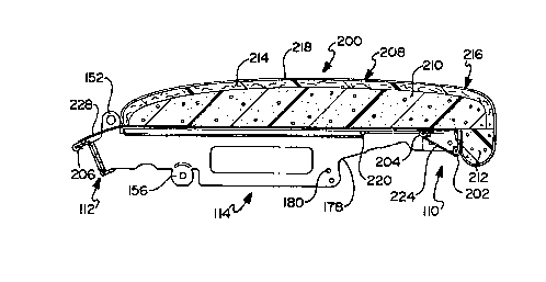
The shape of seat cushion 200 is generally defined by foam cushion 208
having a knee bolster located along the front edge and tapered rear portion
located
along the rear edge. In the presently preferred embodiment, foam cushion 208
is
constructed from two-pieces of suitable foam adhesively bonded together - an
upper
blank 210 which includes the seat and a lower portion 212 which forms a knee
bolster.
Seat cushion 200 further includes contour layer 214 disposed on top of
cushion 208 and the wrapping around knee bolster 212 for providing a smooth
surface with a "stuffed" look. Thermofil~ foam or other suitable material may
be used
for contour layer 214. Outer upholstery fabric layer 216 includes top panel
218 and
side panels 220 (Figure 3) for covering the exposed surtaces of seat cushion
200.
Side panels 220 further include wing portions 222 which can be tucked in
between
seat frame 20 and side frame assemblies 24 to provide a continuous upholstered
look.
taper portions 224, 226 and 228 are stitched to the ends of fabric layer 216
and
substantially cover the unexposed surfaces of foam cushion 208 including the
portions
which abut seat frame 20 to prevent seat springs 136 from abrading foam
cushion
208. A tear resistant material may be is utilized for the liner.
Seat cushion 200 is releasably attached to seat frame 20 by a plurality of
plastic J-strips, including front inner J-strip 202, front outer J-strip 204
and rear J-strip
206. These J-strips are similar to those described in conjunction with fabric
facias
heretofore discussed. Front inner J-strip is disposed on cushion 208 behind
knee
bolster 212 and engages vertical front flange 118. Similarly, front outer J-
strip 204 is
stitched to liner 224 along the front transverse edge of seat cushion 200 and
grasps
horizontal top flange 120 of front cross rail 110. Thus, a smooth attachment
is
- . CA 02202158 1999-10-21
16
achieved by utilizing two attachment strips along the front of cushion 200.
Rear
J-strip 206 is stitched to liner 228 along the rear transverse edge of seat
cushion
200 and grasps upper flange 130 of rear cross rail 1 12.
The dimensions of fabric layer 216 are such that foam cushion 208
must be slightly compressed to appropriately position J-strips 202, 204, and
206
over their respective flanges. When released, the expansion of foam cushion
208
causes J-strips 202, 204, and 206 to be pulled tight against their respective
flanges. Furthermore, the expansion of foam cushion 208 acts to pull fabric
layer
216 taunt on seat cushion 200 and give the cushion an aesthetically pleasing
appearance.
Referring again to Figures 2 and 3, seat back 18 is in the form of a rigid
relatively rectangular assembly. Seat back frame 18 includes right and left
hand
side members 230, 232 and upper and lower cross-pieces 234, 236, respectively.
As is known, seat back frame 18 can be removably mounted on an upper portion
of rear swing links 154 by means of slide brackets 238 secured at suitable
locations
on side members 230, 232. A preferred construction of slide brackets 238 for
this
type of mounting is shown and described in IJ.S. Pat. No. 5,184,871, assigned
to
the common assignee of the present invention. Seat back frame 18 could be
readily
adapted to secure back cushion 240 in a manner similar to seat cushion 200.
For
example, seat back frame 18 could be fabricated from metal frame components
similar to seat assembly 20 of the present invention and back cushion 240
could
be constructed (as shown) for ease of attachment like seat cushion 200.
Leg rest assembly 16 is shown to include leg rest frame board 40
having an outer surface that is padded and upholstered so that finished
reclining/rocking chair 10 will be as seen in Figures 1 A through 1 D. Frame
board
40 is supported and moved by identical left and right hand pantograph linkages
36.
~
. ~ . CA 02202158 1999-10-21
17
Left and right spring-assist toggle assemblies 38 are provided which work
coactively
with leg rest pantograph linkages 36. Toggle assemblies 38 provide means for
securely holding frame board 40 of leg rest assembly 16 in a fully retracted
position.
Toggle assemblies 38 are also operable to supply a spring force for biasingly
urging
leg rest assembly 16 toward one of its extended and retracted positions.
Pantograph linkages 36 and toggle assemblies 38 may be similar in function and
structure to that shown in Figure 3 of U.S. Patent 3,096,121, assigned to the
common Assignee of the present invention, with the exception that pantograph
linkages 36 are operably suspended about 'the second set of "fixed" suspension
points defined by support shaft 32. Alternatively, pantograph linkages 36 and
toggle assemblies 38 may be similar in function and structure to that shown in
Canadian Application Serial No. 2,202,159 entitled "Pawl and Ratchet Assembly"
filed on October 2, 1995 and commonly owned by the assignee of the present
invention. Reference may be made to the above-identified patent and
application.
To provide means for permitting the chair frame 10 to rock relative to
base assembly 22, contoured rocker blocks 242 are provided which are secured
to
side frame assemblies 24. Rocker blocks 242 are positioned to engage an upper
surface of base assembly 22 in a "rockable" relation therewith. Rocker blocks
242
and base assembly 22 are interconnected by a double coil spring "rocker"
device,
generally shown at 244. As will be appreciated, rocker spring device 244 is
operable to permit balanced rocking movement of chair 10 with respect to fixed
base assembly 22 without causing seat assembly 14 to recline inadvertently.
Preferably, rocker spring device 244 is similar to that disclosed in U.S. pat.
No.
5,171,000, commonly owned by the assignee of the present invention.
In accordance with another comfort feature associated with
combination reclining/rocking chair 10, a locking apparatus 246 is provided
that is
~
_ CA 02202158 1999-10-21
18
operable to releasably hold chair 10 in any one of a plurality of rearwardly
"tilted"
positions upon leg rest assembly 16 being selectively moved to its fully
extended
position. Locking apparatus 246 is also operable to inhibit subsequent rocking
movement of chair 10 in a forward direction following movement to a desired
S rearwardly "tilted" position. Preferably, locking apparatus 246 is ratchet
type
locking mechanism that is actuated upon angular movement of drive rod 30. In
general, pawl mechanism 248 acts between ratchet sector 46 and base assembly
22 for providing a number of sequential lockable rearwardly "tilted"
positions.
Presently, preferred examples of locking mechanisms are thoroughly shown and
disclosed in U.S. Patent No. 5,328,235 and Oanadian patent Application Serial
No.
2,202,160 entitled "Dual Leg Rest Assembly" filed on October 12, 1995 and
commonly owned by the assignee of the present invention.
From the foregoing description one skilled in the art will readily
appreciate that the design of the present invention utilizes support shaft 32
to
integrate five positioning and supporting functions of chair 10. The front
portion
of side frame assemblies 24 are located and connected by the ends of support
shaft
32 and end member segments 44 attached thereto. Pantograph linkage assembly
36 is partially suspended from and supported by support shaft 32. The upper
end
of ratchet sector 46 of locking mechanism 246 is secured to and supported by
support shaft 32. Similarly, the front portion of seat frame 20 is supported
support
shaft 32 via front slide brackets 176. In addition, the configuration of
notched
portion 178 formed in side rails 114 enable seat frame 20 to be positioned
closer
to support shaft 32 and thus lower relative to actuation mechanism 12. By
combining these functions into support shaft 32, a chair having integrated
components not heretofore found in other prior art devices is disclosed.
While a general description of the method of assembling the "modular"
~
. ~ . CA 02202158 1999-10-21
19
pre-assembled frame components will now be given, a detailed description of
the
method of assembling is provided in U.S. Patent Nos. 5,222,286 issued on June
29, 1993 and 5,301,413 issued April 12, 1994. The improved method of the
present invention permits sequential assembly of the pre-assembled and/or
upholstered components in a simple and efficient manner for significantly
reducing
overall system complexity, weight and cost while promoting superior quality
and
reliability.
Referring now to Figures 12A through 12H, actuation mechanism 12
including front slide bracket 176 is disposed on support shaft 32 and located
on jig
300. Front cross member assembly 26 including lower cross member segment 42,
end member segments 44 and central member segment 46 are suspended from
support rod 32. Jig 300 may include side portions (not shown? extending
vertically
from the outboard edges of base 300 to align components of front cross member
assembly 26 relative to the components of actuation mechanism 12 such that
lower
cross member segment 42, end member segment 44 and central member segment
46 are perpendicularly situated with respect to drive rod 30 and support rod
32,
while maintaining drive rod 30 and support shaft 32 in parallel alignment.
Once
appropriately positioned, front cross member assembly 26 is secured to support
rod
32 and cross brace 34 with threaded fasteners to form a rigid, unitary
assembly
suspended from jig 300, as best seen in Figure 12B.
Next, side frame assemblies 24 are appropriately positioned on
actuation mechanism 12. Front frame member 26 is aligned and secured to side
frame assemblies 24 with threaded fasteners at three locations per side
through
apertures 58 in end member segments 44. Similarly, rear frame member 28 is
aligned and secured to side frame assembly 24 at two locations per side. Seat
assembly 14 is
CA 02202158 1997-04-08
WO 96/11608 PCT/US95/12795
-20-
appropriately positioned and secured at the front portion to front slide
bracket 176
and at the rear portion to side frame assembly 24. Chair 10 is then removed
from jig
300 and positioned and coupled to chair base assembly 22 to enable rocking
movement thereof.
With reference to Figures 3 and 11 seat cushion 200 having J-strips 202, 204
and 206 is positioned onto seat frame 20. First, J-strip 202 is disposed on
and
engages vertical flange 118. Next, liner portion 224 of seat cushion 200 is
wrapped
under front frame rail 110 such that J-strip 204 engages the edge of
horizontal flange
120 to secure the front edge of seat cushion 200 to seat frame 20. Finally,
rear liner
portion 228 is extended backward such that J-strip 206 engages upper flange
130 of
rear frame rail 112 to secure the rear portion of seat cushion 200 to seat
frame 20.
With reference now to Figures 3, 5 and 6, front fabric facia 80 is located on
and secured to front frame rail 26. J-strip 102 disposed on the lower edge of
center
fabric facia 82 is disposed on and engages horizontal flange 50. The upper
portion
of center fabric facia 82 is positioned relative to ratchet sector 46.
Fastener 104 is
inserted through center fabric facia 82 into aperture 78 for further securing
center
fabric facia 82 to front frame rail segment 26. Similarly, end fabric facia 82
is located
and secured to front frame rail 26. J-strip 102 disposed on the lower edge of
end
fabric facia 96 is disposed on and engages horizontal flange 50. The upper
portion
of end fabric facia 96 is positioned relative to end member segments 44.
Fastener
104 is inserted through end fabric facia 96 into aperture 78 for further
securing end
fabric facia 96 to front frame rail 26.
Referring again to Figures 12A through 12H, assembly of the modular reclining
chair is completed by providing seat back 18 which slidingly engages a portion
of
swing link means 154. As is relatively apparent from examination of the
figures, the
pre-assembled components can be interconnected in a number of other acceptable
CA 02202158 1997-04-08
WO 96/11608 PCT/US95/12795
-21 -
sequential operations to produce "knock-down" or modular chair 10. The method
of
assembly disclosed herein is advantageous in that virtually all of the
components can
be pre-assembled "off-linen for quick and efficient modular interconnection in
a highly
repeatable and precise fashion.
The foregoing discussion discloses and describes an exemplary embodiment
of the present invention. One skilled in the art will readily recognize from
such
discussion, and from the accompanying drawings and claims, that various
changes,
mod~cations and variations can be made therein without departing from the
spirit and
scope of the invention as defined in the following claims.