Note: Descriptions are shown in the official language in which they were submitted.
' CA 02202200 1997-04-09
MEDICAL OR SURGICAL APPLIANCE, IN PARTICULAR
A URL~tE COLLECTION DEVICE
Urine collection devices are known. as are other medical or
surgical appliances which are worn on the body. One example is illustrated in
our U.K. Patent Application No. 2,?96,66~. The present invention aims to
provide an appliance, e.g. a urine collection device of high capacity, which
is
particularly comfortable to wear and yet easy to attach and remove.
In PCT Application No. W096/06646 there is disclosed a coupling device
for a leg urinal. A leg bag has straps. one end of each strap is provided with
loop material and the other end with hook material. The straps can be wrapped
around the leg and easily connected together at a comfortable tension as
determined by the patient. This arrangement has no positive way of ensuring
that
the bag is prevented from shifting its position relative to of the strap.
In U.K. Patent Application No. 2.? 1~,? 1 lA there is shown a urine baa
( 1) made of two flexible sheets ( 10,11 ) welded together at their edges and
along
two vertical lines ( 16,17) to divide the bag into three vertical chambers (
18 to
20). Two pairs of mounting apertures ('?1, 22, 23 and 24) receive respective
straps (2 and 3) by which the bag is secured around the leg (4). The straps (2
and 3) pass behind the bag (1) between the bag and the leg where they have
portions (32) of increased width that are stiffened by folding back at their
ends
(33 and 34). A part (35) of each strap (2 and 3) is elastic and they have
press-to-
close loop and hook fabric fasteners. The portions (32) of greater width limit
the
extent by which the edges of the bag can slide together along the strap as the
bag
tills with urine. thereby reducing bunching. However, if it is desired to
remove
this design of bag from the leg, it is necessary either to withdraw a
considerable
length of strap through the apertures (21 and 22, or 23 and 24), which is time
consuming and awkward for elderly or infirm wearers. or to strip apart the
strap
ends. This stripping apart causes a situation wherein, brietly, the mounting
of
the bag on the leg is insecure. It the bag is full, this will cause
apprehension to
elderly or infirm persons. ft is an aim of the present invention to provide an
' CA 02202200 1997-04-09
improved arrangement.
According to one aspect of the invention, there is provided a method of
attaching a medical or surgical appliance to a part of the body of the wearer
of
the appliance, including providing a pair of slots or holes in the appliance,
providing a band of fabric material of a first kind which has a pair of tabs
permanently fixed thereon. at equal spacing to the holes or slots, each tab
being
of a fabric material of a second kind. threading the band through said holes
or
slots, and releasably securing each tab to the band in face-to-face manner.
In an advantageous embodiment of the invention, the material of the first
kind is a fabric having loops on one of its surfaces and the material of the
second
kind is a fabric having hooks on one of its surfaces.
In use, the band extends around the relevant body part of the wearer and
holds the appliance onto it. once the tab is closed onto the band.
According to another aspect of the invention, there is provided a medical
or surgical appliance having two holes or slots therein through each of which
a
band can be threaded, first and second tabs each permanently attached to the
band, and a fabric of a first kind on at least one surface of the band and a
fabric
of a second kind on at least one surface of each tab, the tabs being located
on the
band such that the distance between them is substantially equal to the
distance
between the holes or slots, and the tabs being connected to the band and
arranged
so that the band can be manipulated to fasten together said surfaces in face-
to-
face arrangement and thereby hold the appliance onto the band.
According to a further aspect of the invention, there is provided a medical
or surgical appliance suitable for attachment to the leg of a wearer, the
appliance
comprising a bag and an attachment means, the bag having two pairs of zones
which are defined by plastics welds and which are sealed against ingress of
liquid, each of these zones being provided with a through slot which is
substantially vertical when the bag is being worn on a wearer who is in a
normal
upright position; and the attachment means comprising at least a pair of
bands,
one such band having a first and second tab thereon permantently attached
thereto
CA 02202200 1997-04-09
-3-
at a mutual spacing substantially equal to the spacing between the slots of
one
pair of zones, and the other such band having a first and a second tab thereon
permanently attached thereto at a mutual spacing substantially equal to the
spacing of the slots of the other pair of zones, each of said tabs having
either a
fabric of a first kind or a fabric of a second kind or a fabric of a first
kind on a
surface which in use confronts the tab whereby these surfaces can be
manipulated
to fasten together in face-to-face arrangement.
In a preferred embodiment. upper and lower bands may be provided.
Desirably the upper band is wider than the lower band.
According to a preferred embodiment the present invention. there is
provided a urine collection device in which a bag, optionally pleated. for
receiving urine is secured in known manner to a pubic attachment plate. has at
least two slots in non-liquid containing regions of the bag, and is connected
to
a leg band via a pair of tabs. the tabs having surfaces which carry hooks or
loops
IS and the band having a surface which carries loops or hooks as the case may
be,
whereby interengagement between the hooks and loops of the respective surfaces
' holds the bag to the band and hence to the wearer.
The invention will be better understood from the following non-limiting
description of an example thereof given with reference to the accompanying
drawings in which:-
Figures IA and IB is a perspective views of two examples of an
appliance, e.g. a urine collection device, according to the invention; like
parts
have like numerals in these Figures;
Figures 2 and 2A show an appliance according to a second embodiment
of the invention;
Figures 3 and 4 show form of band usable ici the invention; and
Figures 5 and 6 show a further embodiment of band usable in the
invention.
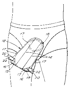
The urine collection device shown in Figure I A comprises a plastics hag
3U 12 having front and rear walls and having pleats l=a- in order to render it
capable
. ' CA 02202200 1997-04-09
of carrying, if necessary, a substantial quantity of urine. The bag is made by
superposing a pair of sheets which are then welded together by a plastics weld
17 which defines the liquid-containing volume of the bag. Areas 16 in the
lower
region of the bag are located outside the weld and contain slots 19
therethrough.
The upper end of the bag is provided with a pubic pressure plate and fitting
18
so that the plate can be fitted to the wearer around his or her pubic area.
For
further information on how such a plate and tilting may be attached to the
body
of a male wearer, the reader is referred to U.K. Patent No. 2 233 232B.
However, other forms of pubic fitting may be employed.
A leg band 20 encircles the leg of the wearer. this band being provided
with a surface area having fabric hooks. A pair of tabs ?? are provided. each
having one of its ends permanently attached to the band ?0. The tabs 22 have
one of their surfaces provided with tabric loops. The loops and hooks referred
to may be of the kind which are found in the well known fastening arrangement
known under the Trade Mark VELCRO. The loops may be on the tabs and the
hooks on the leg band, or the loops may be on the leg band and the hooks on
the
tabs. In use, the tabs are pushed through the slots 19 and folded over as
shown
?0
to engage with the confronting surface of the leg band. The spacing between
the
tabs is substantially equal to that between the holes or slots. Hence the bag
12
can be held smoothly spread out. and supported by the relevant limb of the
wearer. It will be understood that in use the two tabs which may be "Velcro"
are pushed through the slots in the leg bag and fastened back onto the face of
the
band. The face of the band is made up of a loop type material which receives
the hooks on the "Velcro" tabs. Once the tabs are fastened down the bag is
held
secure and is unable to bunch toward its centre. The bands are fastened to the
leg and held in place by a tab (e.g. fi9), see Figure 3. as is commonplace in
the
art. Therefore, the bag is held in a safe. secure and comfortable manner while
yet being readily released for removal it~ required. An arrangement of spaced
slots in a bag together with equally spaced tabs on a band can be employed in
3U various kinds of collection bag, e.g. a le~~-Uag arrangement of the kind
shown in
CA 02202200 1997-04-09
_5_
PCT Application No. W096/06646.
The urine collection device shown in Figure IB is similar, except that it
does not have pleats. Its upper end is in use fixed to a pubic plate and
fitting and
its lower end is secured to a leg of the wearer by a band 20 which is similar
to
that described in connection with Figure LA. In Figure LB, the tabs are not
visible.
Referring now to Figures 2 and 2A, these show a leg bag 30 forming part
of the invention comprising a pair of plastics sheets welded together around
the
periphery by a weld seam 32. A tube connector 34 is welded into the top of the
bag, through which urine enters. A drainage tap 36 welded to a lower portion
of the bag allows urine to be emptied from the bag. The two plastics sheets
are
joined together by the weld seam 32 and the liquid-containing portion of the
bag
is defined by a second weld seam 38 which merges with the weld seam 32 at two
opposed middle regions of the bag. It is seen that these two seams 32, 38
l5 demarcate four zones 40, 42, 44, 46 of the bag from which liquid is
excluded.
Each such zone has a through slot 50. The slots 50 are substantially vertical
when the appliance is in its normal upright position of use, as it would be if
attached to the leg of a person standing upright. The plastics surrounding the
slots is strengthened by a short weld as is more clearly illustrated at 33 in
Figure
2A. This is to prevent the bag film being inadvertently torn. Each of the
slots
SOA to SOD is dimensioned to receive a corresponding tab.
Figures 3 and 4 illustrate in cross-section and plan view respectively, one
form of band usable in the present invention. The band 60 may be made of a
nylon-rubber mixture and is manually extensible to a limited extent. A pair of
tabs 62 are fixed to the band 60, e.g. by stitching as shown at 64, at
locations
along the band 60, the spacing between the stitched areas 64 being
substantially
equal to the spacing between a pair of slots SOA, SOB. As shown in the
drawing,
this spacing is substantially the same as the spacing between slots SOC and
SOD
but it would of course be different if the bag shape were such that it is
wider (or
narrower) at the bottom than at the top. 'fhe side 66 of the band has a loop-
type
~
' CA 02202200 1997-04-09
-6-
fabric thereon and an end portion 68 of the band, stitched to the remainder of
the
band at 70, has (took-type fabric on its surface 69. This enables the ends to
be
joined as desired so that the bag 30 can be attached to a leg. The surfaces
62A
have hook-type fabric theron.
The construction of the band 80 shown in Figures 5 and 6 is generally
similar to that shown in Figures 3 and 4 except that in the Figures 5 and 6
embodiment, instead of two tabs 62, a single strip of suitable material 82 is
attached to the band 80; this has hook-type fabric 84 on the indicated
portions 86
of the material. The side 80A of the band carries loop-type fabric. The
material
l0 82 is stitched to the band 80 at the region 88.
A system comprising a band which carries a pair of tabs fixed thereto, the
tabs in their fastened position cwerlying the band and having either hooks or
loops to cooperate with loops or hooks on the band can of course be employed
to secure various kinds of medical or surgical appliance to the body of a
wearer.
IS For example a catheter or a wound protector could be supported by such an
arrangement. The spacing of the tabs ~~ould be substantially equal to the
spacing
of slots provided in il~e appliance, so as to achieve the benefit of holding
the
appliance on the body without bunching or crumpling.