Note: Descriptions are shown in the official language in which they were submitted.
CA 02202203 2000-10-12
ULTRASONIC VIBRATION CtITTlR
Background of the Invention
This invention relates to a cutter for cutting a
workpiece with ultrasonic vibration.
An ultrasonic vibration cutter is known in which a
cutter such as a dicing blade, diamond cutter or saw blade
is integrally provided in a resonator which resonates with
ultrasonic vibration having a predetermined frequency. Such
a cutter is used as a tool for cutting such species as a
semiconductor chip as a semiconductor element from a wafer
for the production of a semiconductors a metal foil; a
printed circuit board or a synthetic resin substrate.
However, the ultrasonic vibration cutter of the prior
art is uneconomical since the cutter alone cannot be
replaced because the cutter is integrally provided in the
resonator.
Summarv of the Invention
To cope with this problem, the present invention
provides an economically advantageous ultrasonic vibration
cutter which allows for the replacement of the cutter
component.
According to a first aspect of the present invention,
there is provided an ultrasonic vibration cutter for cutting
a workpiece with a cutter installed on a resonator which
resonates with ultrasonic vibration having a predetermined
frequency. Since the cutter is installed at the minimum
amplitude point or in the vicinity thereof, vibration in a
- 1 -
CA 02202203 2000-10-12
cutting direction can be efficiently given to the cutter so
that cutting can be carried out efficiently.
The resonator has a large diameter portion and a male
screw portion projecting coaxially from one end surface of
the large diameter portion. The cutter, having a cutting
blade on a disk-shaped peripheral portion thereof, is fitted
onto the male screw portion, and a nut is fastened to the
male screw portion projecting from this cutter to install
the cutter detachably in such a manner that the cutter is
located at the minimum vibration amplitude point of the
resonator with the nut and the large diameter portion. The
cutter can be fixed firmly with the fastening force of the
nut.
Further, since the cutter is detachably installed with
the nut in such a manner that it is located at the minimum
vibration amplitude point, the cutter can be replaced with
ease by disconnecting the nut from the male screw portion.
More specifically, there is provided ari ultrasonic
vibration cutting device comprising a resonator which
resonates with an ultrasonic vibration having a
predetermined frequency. The resonator has a plurality of
small diameter portions, a large diameter portion and a male
screw portion, wherein the portions are formed as a single
body of the resonator and arranged in a sequence of one of
the small diameter portions, the large diameter portion, the
male screw portion and another of the small diameter
portions in a state of a straight line in an axial direction
from an end of the resonator to another end of the same. At
- 2 -
CA 02202203 2000-10-12
According to a second aspect of the present invention,
there is provided an ultrasonic vibration cutter for cutting
workpieces with two cutters installed on a resonator which
resonates with ultrasonic vibration having a predetermined
frequency. Since the two cutters are detachably installed
at an equal distance from the minimum vibration amplitude
point of the resonator, cutting can be carried out with the
two cutters.
Since the two cutters of the same shape are installed
with nuts with predetermined spacing therebetween, the
cutters can be replaced with ease by disconnecting the nuts
from the male screw portions.
Further, when a plurality of cutters of the same shape
are installed with nuts with predetermined spacing
therebetween, members having a predetermined width can be
cut out from a workpiece.
More specifically, there is provided an ultrasonic
vibration cutting device comprising a resonator which
resonates with an ultrasonic vibration having a
predetermined frequency. The resonator has a plurality of
small diameter portions, a large diameter portion and a
plurality of male screw portions, wherein the portions are
formed as a single body of the resonator and arranged in a
sequence of one of the small diameter portions, one of the
male screw portions, the large diameter portion, another of
the male screw portions and another of the small diameter
portions in a state of a straight line in an axial direction
from an end of the resonator to another end of the same. At
least one of the small diameter portions has a screw
- 2b -
CA 02202203 2000-10-12
connecting means at a center of its end surface for
coaxially connecting a mating member which is to be
connected with the resonator, the large diameter portion is
located at a position of a minimum vibration amplitude point
(a modal point) of the vibration in an axial direction of
the resonator. The male screw portions have a diameter
smaller than that of the larger diameter portion but larger
than that of the small diameter portions. .
The ultrasonic vibration cutting device of this second
aspect of the invention also comprises a plurality of
cutting means of disk shape for cutting a workpiece, each of
the cutting means having a central through-hole fitted over
the male screw portion with contact and having a periphery
working as an annular cutting blade and having a diameter
larger than that of the larger diameter portion.
The ultrasonic vibration cutting device of this second
aspect of the invention further comprises a plurality of nut
means for detachably securing the cutting means to the
resonator, each of the nut means having an external shape
identical with that of the large diameter portion, wherein
the plurality of cutting means are placed with equidistance
with respect to the minimum vibration amplitude point of the
vibration in the axial direction of the resonator by the
large diameter portion. The large diameter portion, cutting
blades of the cutting means, nut means, and male screw
portions are subjected to a vibration mode converted to a
radial direction which is perpendicular to the axial
direction of the resonator at the minimum vibration
amplitude point in the axial direction. This is done under
- 2c -
CA 02202203 2000-10-12
the condition that the cutting means are sandwiched between
the large diameter portion and the nut means which are
secured to the male screw portions after the cutting means
are fitted over the male screw portions.
The above and other objectives, features and advantages
of the invention will become more apparent from the
following description when taken in conjunction with the
accompanying drawings.
Brief Description of the Drawings
Fig. 1 shows a first embodiment of the present
invention, wherein Fig. 1(a) is a perspective view of the
outer appearance of the embodiment, Fig. 1(b) is an exploded
sectional view and Fig. 1(c) is a waveform diagram showing
relationship with vibration waveform.
Fig. 2 shows a second embodiment of the present
invention, wherein Fig. 2(a) is a perspective view of the
outer appearance of the embodiment, Fig. 2(b) is an exploded
sectional view and Fig. 2(c) is a waveform diagram showing
relationship with vibration waveform.
Detailed Description of the Preferred Embodiments
Fig. 1 shows a first embodiment of the present
invention in which a single diamond cutter 2 which projects
in a direction perpendicular to a central axis L is
installed on a single resonator 1 which is molded
substantially cylindrical and has the central axis L by a
single nut 3. The resonator 1 has a large diameter portion
la having a smaller diameter than that of the diamond cutter
- 3 -
CA 02202203 1997-04-09
2, a small diameter portion lb coaxially provided on one end
surface of the large diameter portion la, a male screw
portion 1c coaxially provided on the other end surface of
the large diameter portion la and fitted into a through hole
2a of the diamond cutter 2, a small diameter portion ld
coaxially provided on an end surface of the male screw
portion lc, and screw holes ie and if formed in the centers
of the end surfaces of the small diameter portions lb and
ld. A commercial product having a through hole 2a in the
center is used as the diamond cutter 2. The nut 3 has a
threaded portion 3a to be fitted onto the male screw portion
lb of the resonator 1.
In this embodiment, the through hole 2a of the diamond
cutter 2 a.s fitted onto the male screw portion lc of the
resonator i, the nut 3 is fitted onto the male screw portion
lc projecting from the through hole 2a, and a fastening tool
is fitted into one of tool holes,, not shown, formed in the
outer peripheral surfaces of the small diameter portions lb
and ld of the resonator 1 to fasten the nut 3 firmly by
rotating it in a.fastening direction, whereby the single
diamond cutter 2 is brought into close contact with the
large diameter portion la of the resonator 1 in such a
manner that it is coaxially sandwiched between the large .
diameter portion 1a and the nut 3 and an outer peripheral
portion of the diamond cutter 2 which is a cutting blade
having diamond powders adhered thereto projects outward from
the resonator 1. In this assembled ultrasonic vibration
cutter, the output end of a transducer which is an electro- -
acoustic or electro-vibration transducer formed of a
CA 02202203 1997-04-09
piezoelectric element or magnetostrictive element for
converting into mechanical energy electric energy which is
output by generating vertical ultrasonic vibration having a
predetermined frequency with power supplied from an unshown
ultrasonic generator is coaxially connected to the small
diameter portion lb of the resonator 1 with the screw hole
1e in the resonator 1, an unshown screw hole formed in the
output end of the transducer and unshown headless screws to
be screwed into these screw holes. This resonator 1 is
formed like a. rod from super steel such as SKD11 or the like
and hardened in a vacuum atmosphere, or is formed like a rod
from a sintered metal. The resonator 1 is an ultrasonic
horn itself which applies ultrasonic vibration transmitted
from the unshown transducer connected thereto to the diamond
cutter 2 and has a length equal to half the wavelength from
the maximum vibration amplitude point fl to the maximum
vibration amplitude point f3 as shown in Fig. 1(c) while the
diamond cutter 2 is installed on the resonator 1 in such a
manner that it a.s sandwiched between the resonator 1 and the
nut 3 when the resonator 1 is seen from the transducer. The
minimum amplitude point f2 is located at an intermediate
position of the thickness of the diamond cutter 2 attached
to the resonator 1. In this case, the large diameter
portion 1a and the male screw portion lc of the resonator 1
and the nut 3 constitute the fastening unit A of the present
invention.
According to the structure of this embodiment, since
the diamond cutter 2 is sandwiched between the resonator 1
and the nut 3, the diamond cutter 2 can be exchanged with
- 5-
CA 02202203 1997-04-09
ease by fitting the fastening tool into the above unshown
tool hole formed in the.resonator 1 and rotating the nut in
a loosening direction. Therefore, this embodiment is
economically advantageous.
The unshown transducer is connected to one end of this
assembled ultrasonic vibration cutter and then this assembly
is attached to a holding portion of an ultrasonic vibration
cutting machine with one side or both sides thereof
supported by the holding portion so that it is rotated
driven by an unshown motor or rotated along with the
horizontal movement of the holder. When the resonator 1 is
resonated with vertical ultrasonic vibration by supplying
power to the transducer, as shown in Fig. l(c), vibrations
indicated by W rtual lines Z1 and L2 which cross each other
at a right angle at the minimum amplitude point f2 and
resonate with each other are generated alternately in the
resonator 1, portions located at the maximum vibration
amplitude points f1 and f3 of the resonator 1 vibrate in a
direction shown by an arrow xl in Fig. 1(c), and the cutting
blade of the diamond cutter 2 located at the minimum
vibration amplitude point f2 vibrates in a direction shown
by an arrow Y1 in Fig. 1(c) which is perpendicular to the
direction shown by the .arrow xl. The outer peripheral
portion of the diamond cutter 2 is brought into contact with
a portion to be cut of a workpiece such as a wafer, metal
foil, printed circuit board or synthetic resin substrate by
the above rotation driven by the motor or rotation along
with the horizontal movement of the holder to cut a
semiconductor chip as a semiconductor element from a wafer,
CA 02202203 1997-04-09
metal foil, printed circuit board or synthetic.resin
substrate.
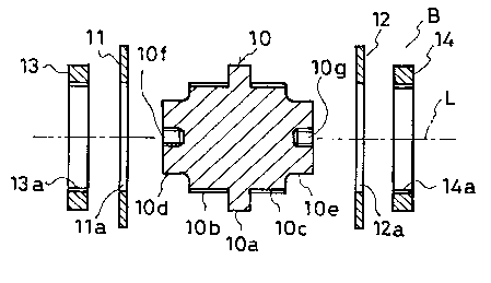
Fig. 2 shows a second embodiment of the present
invention. Two diamond cutters 11 and 12 of the same shape
which project in a direction perpendicular to the central
axis L are installed on the outer peripheral surface of a
single resonator 10 formed substantially cylindrical and
having the central axis L with two nuts 13 and 14 in such a
manner that there is predetermined spacing between the
cutters 11 and 12. The resonator 10 has a large diameter
portion lDa having a smaller diameter than those of the
diamond cutters 11 and 12, male screw portions 10b and 10c
to be fitted into through holes 11a and 12a formed in the
diamond cutters 11 and 12 and coaxially provided on both end
surfaces of"the large diameter portion 10, small diameter
portions lOd and 10e coaxially provided on the end surfaces
of the male screw portions lOb and lOc, and screw holes i0f
and lOg formed in the centers of the end surfaces of the
small diameter portions i0d and 10e, respectively.
Commercial products having through holes lla and 12a in the
centers thereof are used as the diamond cutters 11 and 12.
The nuts 13 and 14 have threaded portions 13a and 14a to be
fitted onto the male screw portions lOb and lOc of the
resonator 10, respectively.
In this embodiment, the through hole 11a of the diamond
cutter 11 is fitted onto the male screw portion lOb of the
resonator 10, the nut 13 is fitted onto the male screw
portion lOb projecting from the through hole lla, and a
fastening tool is fitted into a tool hole, not shown, formed
CA 02202203 1997-04-09
in the outer peripheral surface of the small diameter
portion 10d of the resonator 10 to fasten the nut 13 firmly
by rotating it in a fastening direction. Meanwhile, the
through hole 12a of the diamond cutter 12 is fitted onto the
male screw portion i0c of the resonator i0, the nut 14 is
fitted onto the male screw portion lOc projecting from the
through hole 12a, and a fastening tool is fitted into a tool
hole, not shown, formed in the outer peripheral surface of
the small diameter portion 10e of the resonator 10 to fasten
the nut 14 firmly by rotating it in a fastening direction.
Thereby, the two diamond cutters 11 and 12 are brought into
close contact with the large diameter portion l0a of the
resonator to in such a manner that they are coaxially
sandwiched between the large diameter portion l0a and the
nuts 13 and_.i4, respectively, with predetermined spacing
therebetween which is the thickness of the large diameter
portion l0a and outer peripheral portions of the diamond
cutters 11 and 12 which are cutting blades having diamond
powders adhered thereto project outward from the resonator
10. In this assembled ultrasonic vibration cutter, the
output end of a transducer which is an electro-acoustic or
electro-vibration transducer formed of a piezoelectric
element or magnetostrictive element for converting into
mechanical energy electric energy which is output by
generating vertical ultrasonic vibration having a
predetermined frequency with power supplied from the unshown
ultrasonic generator is coaxially connected to the small
diameter portion 10d of the resonator 10 with the screw hole
lOf in the resonator 10, an unshown screw hole formed in the
_$_
-CA 02202203 1997-04-09
output.end of the transducer and unshown headless screws to
be screwed into these screw holes. This resonator 10 is
formed like a rod from super steel such as SRD11 or the like
and hardened in a vacuum atmosphere, or is formed like a rod
from a sintered metal. The resonator 10 is an ultrasonic
horn itself which applies ultrasonic vibration transmitted
from the unshown transducer connected thereto to the diamond
cutters 11 and 12. While the diamond cutters 11 and 12 are
installed on the resonator 10 in such a manner that they are
sandwiched between the resonator 10 and the nuts 13 and 14,
respectively, when the resonator 10 is seen from the
transducer, as shown in Fig. 2(c), vibrations indicated by
virtual lines Z11 and L12 which cross each other at a right
angle at the minimum vibration amplitude point f12 and
resonate with each other are generated alternately in the
resonator 10, the resonator 10 has a length half the
wavelength from the maximum vibration amplitude point fil to
the maximum vibration amplitude point f13, the minimum
amplitude point fl2 is located at an intermediate position
of the thickness of the large diameter portion 10a of the
resonator 10, and the two diamond cutters 11 and 12 are
located on both sides of the minimum vibration amplitude
point f12 at an equal distance therefrom. In this case, the
large diameter portion l0a and the male screw portions lOb
and lOc of the resonator 10 and the nuts 13 and 14
constitute the fastening unit B of the present invention.
According to the structure of this embodiment, since
the two diamond cutters 11 and 12 are installed on the
resonator 10 with the nuts 13 and 14, a fastening tool is
-9-
CA 02202203 1997-04-09
r
inserted into one or both of the unshown tool holes formed
in the outer peripheral surfaces of the small diameter
portions lOd and l0e of the resonator IO and the nuts 13 and
14 are rotated in a loosening direction to exchange the
diamond cutters 11 and 12 with ease. Therefore, it is
economically advantageous.
The unshown transducer is connected to one end of this
assembled ultrasonic vibration cutter and then this assembly
is attached to a holding portion of an ultrasonic vibration
cutting machine with one side or both sides thereof
supported by the holding portion so that it is rotated
driven by an unshown motor or rotated along with the
horizontal movement of the holder. When the resonator 10 is
resonated with vertical ultrasonic vibration by supplying
power to the transducer, as shown in Fig. 2(c), portions
located at the maximum vibration amplitude points fll and
f13 of the resonator 10 vibrate in a direction shown by an
arrow X2 in Fig. 2{c), and the cutting blades of the diamond
cutters 11 and 12 located in the vicinity of the minimum
vibration amplitude point f12 vibrate in a direction shown
by an arrow Y2 in Fig. 2(c) which is perpendicular to the
direction shown by the arrow X2. The outer peripheral
portions of the diamond cutters 11 and 12 are brought into
contact with portions to be cut of a workpiece such as a
wafer, metal foil, printed circuit board or synthetic resin
substrate by the above rotation driven by the motor or
rotation along with the horizontal movement of the holder to
cut a semiconductor chip as a semiconductor element from a
-10-
CA 02202203 1997-04-09
wafer, metal foil, printed circuit board or synthetic resin
substrate to a predetermined width.
In this second embodiment, cutting to a width other
than the predetermined width as in the first embodiment is
possible using the cutter 11, for example. In this case,
when the material of a workpiece is soft like a synthetic
resin with a small vibration amplitude, cutting may be
carried out by removing the other cutter 12 and installing
the nut 14. However, when the material of a workpiece is
hard like a wafer or a metal foil with a large vibration
amplitude, the vibration amplitude must be well balanced
using an unshown dummy cutter having substantially the same
mass as that of the cutter 12 in place of the cutter 12.
The diameter of the dummy cutter is made smaller than that
of the cutter 11 used for cutting to prevent the dummy
cutter from contacting the workpiece while the cutter 11
cuts the workpiece in contact with the workpiece with the
result that a cutting operation can be performed properly.
In the first and second embodiments, when the vibration
amplitude is large, it is recommended to reduce the
thicknesses in a radial direction of the nuts 3, 13 and 14,
namely, the thicknesses between the threaded portions 3a,
13a and 14a and the outer peripheral surfaces thereof so. as
to reduce a vibration energy loss. In this case, when the
outer diameters of the nuts 3, 13 and 14 are made
substantially equal to the outer diameters of the large
diameter portions la and l0a of the resonators 1 and 10 and
the outer diameters of the male screw portions lc, lOb and -
lOc of the resonators 1 and 10 and the inner diameters. of
-11-
CA 02202203 1997-04-09
the threaded portions 3a, 13a and 14a of the nuts 3, 13 and
14 are made large to reduce the thick~esses in a radial
direction of the nuts 3, 13 and 14, the vibration amplitude
is well balanced.
In the first and second embodiments, when the fastening
directions of the nuts 3, 13 and 14 are set to a fastening
direction with respect to the rotation directions of the
cutters 2, 11 and 12 during a cutting operation, the nuts 3,
13 and 14 can be prevented from being loosened during a
cutting operation.
In Figs. 1 and 2, the cutting blades of the diamond
cutters 2, 11 and 12 are simply illustrated to have a
rectangular section. It is the most common that these
cutting blades are actually formed to have a wedge-shaped
section. ..
If a dicing blade or saw blade other than the diamond
cutters 2, 11 and i2 is used as a cutter according to the
material of a workpiece, the same function and effect as
those of the above embodiments can be obtained.
A plurality of structures in which two cutters are
installed on both sides of the large diameter portion l0a of
the resonator 10 with the nuts 13 and 14 may be provided on
the outer peripheral surface~of the resonator i0 as a matter
of course. Alternatively, a plurality of structures in
which one cutter is installed on one side of the large
diameter portion la of the resonator 1 with the nut 3 may be
provided on the outer peripheral surface of the resonator 1
as a matter of course.
-12-