Note: Descriptions are shown in the official language in which they were submitted.
CA 02202262 1997-04-09
WO96/16753 PCT~S95/13983
Description
FIN FOLDING MACHINE FOR CORRUGATING SHEET MATERIAL
Technical Field
This invention relates generally to
apparatus for corrugating sheet material for use in
heat exchangers or recuperators and, more
particularly, to an improved fin folding machine with
mechanically actuated forming and clamping members
capable of increased forming speed.
Backqround Art
Apparatus for corrugating sheet material for
use as the primary surface plates of heat exchangers
or recuperators for gas turbine engines and the like
are known in the art. In one technique, as disclosed
in U.S. Patent No. 3,892,119, by Kenneth J. Miller
et.al., issued 01 July 1975, corrugating apparatus
sequentially folds relatively thin sheet material into
closely spaced, deeply drawn serpentine convolutions.
Such apparatus can produce about 40 fins per inch with
a height of about 3.175 mm (0.125 inches), thus
providing a large surface area that is essential for
high capacity heat exchangers. However, this
apparatus uses opposed forming members that are
powered by hydraulic cylinders. In addition, the
forming members are carried on relatively massive
pivotally mounted shoes. While the apparatus works
quite well at slower speeds, it can not be run
satisfactorily at a speed exceeding more than 150
cycles per minute. Above this limit, the forming
members tend to overshoot their desired depth of
formation positions, even with the use of mechanical
stops. Thus, precise fin height is lost and the thin
sheet material may be over stressed, causing tears or
other failures.
CA 02202262 1997-04-09
W O 96/167S3 PC~r~US95/13983
--2
The present invention is directed to
overcoming the shortcomings of prior fin folding
machines by providing a fin folding machine that is
capable of forming thin sheet material into high
aspect ratio serpentine corrugations at a more
productive operating speed.
Disclosure of the Invention
In accordance with one aspect of the present
invention, a fin folding machine is provided for
sequentially folding relatively thin sheet metal
material into narrowly grooved corrugations. The fin
folding machine includes a pair of opposed clamping
tools disposed on opposite sides of the sheet
material. The clamping tools are movable in a
direction transverse to and into engagement with the
sheet material to clamp the sheet material
therebetween. A pair o~ opposed forming tools are
disposed on opposite sides of the sheet material and
are sequentially movable in a direction transverse to
and into engagement with the sheet material to fold
the sheet material in one direction by the engagement
of one of the forming tools and then in the opposite
direction by the engagement of the other of the
forming tools. At least four accumulators are
included, each of which is adapted to apply a force to
continuously urge a respective one of the clamping and
forming tools into engagement with the sheet material.
At least four camming devices are also included, each
being adapted to move a respective one of the clamping
and forming tools away from engagement with the sheet
material to a clearance position, and to prevent its
respective clamping or forming tool from exceeding a
predetermined material engagement stop position
CA 02202262 lss7-04-os
WO96/16753 PCT~S95/13983
regardless of the operating speed of the fin folding
machine.
Brief Description of the Drawinqs
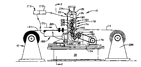
Fig. 1 is a diagrammatic side elevational
view of a fin folding machine embodying the principles
of the present invention in association with a
material feeder for thin sheet material and in which a
portion of an upright side support for the machine has
been broken away to disclose the drive system;
Fig. 2 is a diagrammatic end elevational
view of the fin folding machine as viewed in the
direction of the arrows 2-2 in Fig. 1 and in which,
for clarity, the material feeder has been removed;
Fig. 3 is a diagrammatic enlarged
fragmentary sectional view of one of the side support
members illustrating the clamping and forming members
and their connection to the accumulator system as
viewed in the direction of the arrows 3-3 in Fig. 2;
Fig. 4-8 are diagrammatic side views
illustrating the various sequential positions of the
clamping and forming members during operation from
their fully opened position illustrated in Fig. 4 to
their fully closed position illustrated in Fig.8;
Fig. 9 is graph illustrating cam
displacement in degrees of rotation for the four cams
and their relative cam profiles; and
Fig. 10 is a diagrammatic fragmentary
sectional view of the linear bearings for orientation
and guiding of the elongate plates of the clamping and
forming tools;
Fig. 11 is a diagrammatic enlarged
fragmentary isometric view illustrating the general
construction of one of the forming members of the
present invention; and
CA 02202262 1997-04-09
WO96tl6753 PCT~S95/13983
Fig. 12 is a diagrammatic isometric view of
a formed corrugation produced by the fin folding
machine utilizing the principles of the subject
invention.
Best Mode for Carryinq Out the Invention
Referring more particularly to the drawings,
a fin folding machine embodying the principles of the
present invention is generally indicated at 10 in
Figs. 1 and 2. The fin folding machine 10 is for use
in sequentially folding substantially flat, relatively
thin sheet material, indicated at 12, into a narrowly
grooved corrugated configuration 14, as best seen in
Figs. 3-8 and 12, by sequential single-fold forming
steps which will hereinafter be described. The sheet
material 12 is preferably stainless steel having a
thickness of approximately .8 mm (0.003 inches). Such
stainless steel sheet material 12 is commonly
commercially available in large rolls of 304.8 mm (12
inches) wide material. Such rolls may be supported on
a free wheeling delivery reel stand 16 for delivery to
the machine 10 along a generally horizontally disposed
path 18 (Fig. 3).
As best shown in Fig 2, the fin folding machine
10 includes a frame structure 20 having an opening 22
therethrough defined by a pair of upright side support
members 24, 26, a top support member 28 between the
upper ends of the side support members 24, and a base
support member 30 between the lower ends of the side
support members 24, 26.
To sequentially fold the relatively thin
sheet metal material 12 into the narrowly grooved
corrugations 14, the fin folding machine 10 includes a
pair of opposed upper and lower clamping tools 32, 34,
as shown in Fig.3, which are disposed on opposite
CA 02202262 1997-04-09
WO96/16753 PCT~S95/13983
sides of the sheet material 12, and a pair of upper
and lower opposed forming tools 36, 38, which are also
disposed on opposite sides of the sheet material 12.
The clamping tools 32, 34 are movable in a direction
transverse to and into engagement with the sheet
material 12 to clamp the sheet material therebetween.
The forming tools 36, 38 are similarly sequentially
movable in a direction transverse to and into
engagement with the sheet material 12 to fold the
sheet material in one direction by the engagement of
the first forming tool 36 and then in the opposite
direction by the engagement of the second forming tool
38.
After transformation, as best shown in Fig.
12, the corrugated material 14 includes a plurality of
alternating upwardly and downwardly opening,
transversely extending, relatively deep serpentine
grooves 42 and 44 having relatively closely spaced,
substantially vertical sidewalls or fins 46 as they
are commonly called.
Each of the clamping and forming tools 32,
34, 36, 38, as best shown in Figs 4-8 and 11,
includes an elongated plate 48, a tool holder 50
attached to one end of its respective plate 48, and a
tool 52 attached to the tool holder 50. The tool 52
of the first or upper clamping tool 32 is provided
with a downwardly extending serpentine knife blade
portion 56 (Fig.4). Such blade portion 56 is
configured to be received into the last to be formed
upwardly opening groove 42. The tool 52 of the second
or lower clamping tool 34 is provided with an upwardly
extending serpentine knife blade portion 60 that is
configured to be received against the last fin 46 to
be formed of the last formed groove 42 and in a
closely spaced offset and mating-relation to the blade
CA 02202262 lss7-04-os
WO96/16753 PCT~S95/13983
portion 56 of the first clamping tool 32 so as to
clamp the material 12 therebetween during the forming
operation. The tool 52 of the first or upper forming
tool 36 has a similar knife blade portion 62, while
the tool 52 of the second or lower forming tool 38 is
provided with a serpentine die forming side surface 64
and a substantially flat distal end surface 68. The
distal end surface 68 and an opposed end surface 70
formed on the upper forming tool 36 cooperate to
flatten or de-wrinkle the sheet material 12 adjacent
the last formed fin 46 as shown in Fig. 8.
As shown in Figs 2 and 10, each of the
elongated plates 48 are oriented transversely between
the side support members 24, 26 of the frame structure
20 and each has a first end 72 adjacent one of the
side support members 24 and a second opposite end 74
adjacent the other of the side support members 26.
Linear bearing means 76 are provided for
reciprocatably mounting each of the elongated plates
48 to the frame structure 20 for movement of each
plate 48 along a linear path transverse to the sheet
material 12. Such bearing means 76 preferably
includes a pair of vertically aligned bearing sets 80,
82, each carried adjacent one of the ends 72, 74 of a
25 respective one of the four elongated plates 48. Each
bearing 80, 82 is disposed in slidable bearing contact
with and is guided by a bracket 84 that is attached to
a respective one of the uprights side supports 24, 26
of the frame structure 20. Bearing means 76 also
includes appropriate sets of mating linear bearings
86, 88 carried on a respective one of first and second
sides go, 92 of the four elongated plates 48, and in
facing relationship to each other, the bearings 86 on
one such plate 48 being in slidable bearing contact
35 with the bearing 88 of the facing plate 48. Such
CA 02202262 1997 - 04 - 09
W096l16753 PCT~S95tl3983
--7--
bearings 80, 82, 86, 88 may be made of any suitable
anti-friction material, such as bronze.
As illustrated in Figs. 2 and 3, the fin
folding machine 10 also includes an accumulator system
94 for applying a substantially continuous force on
each of the clamping and forming tools 32, 34, 36, and
38 to urge each of the tools into engagement with the
sheet material 12. The accumulator system 94
preferably includes a pair of nitrogen gas cylinders
96, 98 for each of the clamping and forming tools 32,
34, 36, and 38. Each of the upper elongated plates 48
of the clamping and forming tools 32 and 36 have a top
end 100 adjacent the top support member 28, while each
of the lower plates 48 of the clamping and forming
tools 34 and 38 have a bottom end 101 adjacent the
base support member 30. Each pair of gas cylinders 96,
98 are mounted between a respective one of the top
support member 28 and the base support member 30 and
an adjacent end 100, 101 of their respective elongated
plates 48. Each gas cylinder 96, 98 is charged with a
substantial gas pressure sufficient to cause the
clamping tools 32, 34 to clamp the sheet material 12
therebetween and each of the forming tools 32, 34 to
fold such sheet material. Nitrogen gas cylinders 96,
98 with a gas charge pressure of approximately 103,350
kPa (15,000 p.s.i.) have been found to be suitable.
As best shown in Figs. 4-8, two sets of four
camming devices 102, 104, 106, and 108 are provided to
overcome the accumulator force of cylinders 96, 98 and
to move a respective one of the clamping and forming
tools 32, 34, 36, and 38 away from engagement with the
sheet material 12 to a clearance position.shown in
Fig. 4. It should be noted that the set of camming
devices shown in Figs. 4-8 are at one end 72 of the
elongated plates 48. A matching set of cams are
CA 02202262 1997-04-09
WO96/16753 PCT~S95/13983
located at the other end 74 of the elongated plates,
but as they are the mirror image of the first set,
they are not shown in the drawings.
Each of the camming devices 102, 104, 106,
and 108 is also adapted to prevent its respective
clamping or forming tool 32, 34, 36, or 38 from
exceeding a predetermined sheet material engagement
stop position regardless of the operating speed of the
fin folding machine. To accomplish this, each set of
the camming devices 102, 104, 106, and 108 includes a
pair of cam followers, only one of which is shown at
112 in Fig. 4-8, and an associated pair of cams, one
of which is shown at 116, for each of the clamping
tools 32, 34 and the forming tools 36, 38. A
respective one of the pair of cam followers 112 is
rotatably carried on one of the opposite ends 72, 74
of each of the elongated plates 48. Each cam 116 is
rotatably carried on an adjacent one of the side
support members 24 or 26.
In particular, each of the pairs of cams 116
includes a first pair of cams, one of which is shown
at 122, for operating the first one of the clamping
tools 32, a second pair of cams, one of which is shown
at 124, for operating the second one of the clamping
tools 34, a third pair of cams, one of which is shown
at 126, for operating the first one of the forming
tools 36, and a fourth pair of cams, one of which is
shown at 128, for operating the second one of the
forming tools 38. Each of the cams 122, 124, 126, and
-30 128 is provided with a different predetermined
profile, with each having a full null portion at 132
and a full lifting lobe portion at 134 thereon. Each
full lifting lobe portion 134 is adapted to lift its
respective tool 32, 34, 36, and 38 to the sheet
material clearance position shown in Fig. 4, while the
CA 02202262 1997-04-09
WO 96/16753 PCT/US95/13983
full null portion 132 is adapted to permit its
respective tool to assume its predetermined sheet
material engagement stop position as shown in Fig. 8.
The cams 122, 124, 126, and 128 are also interposed
the sheet material 12 and its respective cam follower
112 to mechanically prevent its respective tool from
overrunning its predetermined sheet material stop
position.
While in actuality, cams 122 and 124 may
rotate in one direction while cams 126 and 128 rotate
in the opposite direction, all of the cams are shown
as rotating in a clockwise direction in Figs. 4-8 for
the sake of clarity. Also, the relative angular
position of each cam is indicated by an arrow 136 in
Fig. 6.
As indicated in Fig. 7, the profile of each
cam 122, 124, 126, 128 has a lowering transition
portion 138 between the lobe and null portions 134,
132 on one side of the cams and a raising transition
portion 140 between the lobe and null portions on the
other side. The terminus of the lowering transition
portion 138 with the lobe portion 134 of each cam
provides a first or end of lobe point 142, while its
terminus with the null portion 132 provides a second
or start of null point 144. Likewise, the terminus of
the raising transition portion 140 with the null
portion 132 provides a third or end of null point 146,
while its terminus with the lobe portion 134 provides
a fourth or start of lobe point 148.
The profiles of the cams 122, 124, 126 and
128 are graphically illustrated in Fig. 9 and numbered
as cam profiles #1, #2, #3 and #4, respectively. In
Fig. 9, it can readily be seen that end of lobe point
142 for cam profile #1 of cam 122 is located at 0
degrees of cam displacement and transcends downward
CA 02202262 1997-04-09
WO 96/16753 PCT/US95113983
--10--
along the lowering transition portion 138 to the start
of null point 144 at approximately 60 degrees of
displacement. From there, the profile of cam 122
proceeds along the null portion 132 until reaching the
5 end of null point 146 after approximately 250 degrees
of displacement. The profile then proceeds up the
raising transition portion 140 to the start of lobe
point 148, and then along the lobe portion 134 to the
starting point at 0 degrees. The end of lobe point
142 for cam profile #2 is generally coincident to the
start of null point 144 for cam profile #1, delaying
its lowering transition portion 138 relative to cam
profile #1. Likewise, the lowering transition
portions 138 of cam profiles #3 and #4 are
sequentially delayed, as can be seen in Fig. 9, to
actuate the cams 122, 124, 126 and 128 in a sequential
fashion. All of the raising transition portions could
be coincident to each other. However, the raising
transition portions 140 of cam profiles #2 and #3
preferably precede those of cam profiles #1 and #4 to
allow for smoother operation of the machine 10.
With this arrangement, starting with all of
the tools 32, 34, 36, and 38 in their clearance
position shown in Fig. 4, the first or upper clamping
tool 32 will be the first to move to its sheet
material stop position, followed closely by movement
of the second or lower clamping tool 34 to its stop
position, which is then followed by the first or upper
forming tool 36 and lastly by the second or lower
forming tool 38 to their respective stop positions.
After all of the tools 32, 34, 36, and 38 reach their
stop positions, the lower clamping tool 34 and the
upper forming tool 36 will return together to their
clearance positions, followed closely by the upper
clamping tool 32 and the lower forming tool 38.
CA 02202262 1997-04-09
WO96/16753 PCT~S95/13983
--11--
As shown in Figs. 1 and 2, the fin folding
machine 10 is also provided with a material feeder 168
for intermittently feeding a preselected length of the
sheet metal material 12 in a first direction as
indicated by the arrow 170, into the opening 22 of the
fin folding machine 10. The feeder 168 is adapted to
permit unrestricted travel of the material 12 in the
first direction 170, but prevents the travel of the
material in an opposite direction.
A drive system 174, shown in Fig. 1,
includes an electric motor 176 and a drive train 178
adapted to be driven by the motor and is provided for
rotatably driving each of the cams 122, 124, 126, and
128 that are rotatably mounted in side support member
24. A similar gear train 178, not shown, is provided
on the opposite side support member 26 to drive the
cams 122, 124, 126, and 128 mounted therein in a
similar fashion. The motor 176 is drivingly connected
to a main cross shaft 192 by a drive belt 194. The
cross shaft 192 extends between the side support
members 24. As shown in Fig. 1, the cross shaft 192
has a spur gear 196 that meshes with an idler gear 198
that is rotatably mounted to the side support member
24. The idler gear 198, in turn, is meshed with a
spur gear 200 for the second cam 124. The spur gear
200 for the second cam 124, in turn, is meshed with a
spur gear 202 for the fourth cam 128. An idler gear
204 is rotatably mounted to the side support member 24
and is used to transfer the driving motion of the spur
gear 202 for the fourth cam 128 to a spur gear 206 for
the third cam 126. The spur gear 206 for the third
cam 126 is, in turn, meshed with a spur gear 208 for
the first cam 122. A common shaft 190 is used to
connect each of the spur gears 200, 202, 206 and 208
to its respective cams 124, 128, 126 and 122.
CA 02202262 l997-04-09
WO 96/16753 PCT~S95/13983
- 12 -
A control system 210 is provided for
controlling the material feeder 168 when the drive
system 174 is in operation. The control system 210
includes a controller 212 and a sensor 214. The
sensor 214 is adapted to sense the angular position of
the camming devices 102, 104, 106, and 108 and to
deliver a control signal to the controller 212. The
controller 212 is adapted to actuate the material
feeder 168 in response to the control signal to cause
the material feeder 168 to advance the sheet material
12 when the clamping and forming tools 32, 34, 36, and
38 are all in their respective clearance positions.
As best shown in Fig. 3, the fin folding
machine 10 further includes an inlet guide 224 for
guiding the sheet material 12 along the predetermined
path 18 toward the clamping and forming tools 32, 34,
36, and 38 and an outlet guide 226 for guiding the
corrugated material 14 along the path away from the
clamping and forming tools. As shown in Fig. 1, a
take-up reel stand 228 is also preferably provided for
receiving the corrugated material 14 from the fin
folding machine 10.
Industrial ApPlicability
The fin folding machine 10 constructed in
accordance with the teachings of the present invention
advantageously forms thin sheet metal material 12 into
high aspect ratio, serpentine corrugations 14 suitable
for use as the primary surface plates of heat
exchangers or recuperators at a higher forming speed
than heretofore possible. Such higher forming speed
is made possible by the use of cams 122, 124, 126, and
128 and accumulators 96, 98. The high pressure
accumulators 96, 98 are effective in keeping the cam
followers 112 for the forming and clamping tools 32,
CA 02202262 1997-04-09
WO 96/167S3 rCl~lUS95113g83
--13--
34, 36, and 38 in continuous contact with the cams
122, 124, 126 and 128, while the location of the cams
on the inside of the cam followers 11 provide a
physical stop and prevent the forming and clamping
tools 32, 34, 36, and 38 from overshooting the desired
forming or clamping positions, regardless of the speed
of the forming operation. As a consequence, more
precisely formed corrugations 14 are obtainable at
higher forming rates, thus increasing production,
while reducing the amount of scrap due to misformed
material.
Because the clamping and forming tools 32,
34, 36, and 38 move in a linear, rather than an
arcuate, path, the present fin folding machine 10 also
improves the life of the knife blades 56, 60, and 62
used in the clamping and forming tools 32, 34 and 36.
This is because the amount of sliding movement between
the sheet material 12 and the sides of the blades 56,
60, and 62 and the amount of bending loads on the
blades are reduced. As a consequence, the blades 56,
60, and 62 do not wear out as fast, nor do they break
as often.
Other aspects, objects and advantages of the
present invention can be obtained for a study of the
drawings, the disclosure and the appended claims.