Language selection

Search

Patent 2202386 Summary

Third-party information liability

Some of the information on this Web page has been provided by external sources. The Government of Canada is not responsible for the accuracy, reliability or currency of the information supplied by external sources. Users wishing to rely upon this information should consult directly with the source of the information. Content provided by external sources is not subject to official languages, privacy and accessibility requirements.

Claims and Abstract availability

Any discrepancies in the text and image of the Claims and Abstract are due to differing posting times. Text of the Claims and Abstract are posted:

  • At the time the application is open to public inspection;
  • At the time of issue of the patent (grant).
(12) Patent Application: (11) CA 2202386
(54) English Title: PAPERBOARD INTERLOCK ARRANGEMENT
(54) French Title: SYSTEME D'ASSEMBLAGE PAR ENCHEVETREMENT POUR MORCEAUX DE CARTON
Status: Deemed Abandoned and Beyond the Period of Reinstatement - Pending Response to Notice of Disregarded Communication
Bibliographic Data
(51) International Patent Classification (IPC):
  • B65D 71/00 (2006.01)
(72) Inventors :
  • BRIAND, NATHALIE (France)
(73) Owners :
  • RIVERWOOD INTERNATIONAL CORPORATION
  • RIVERWOOD INTERNATIONAL CORPORATION
(71) Applicants :
  • RIVERWOOD INTERNATIONAL CORPORATION (United States of America)
  • RIVERWOOD INTERNATIONAL CORPORATION (United States of America)
(74) Agent: GOWLING WLG (CANADA) LLP
(74) Associate agent:
(45) Issued:
(86) PCT Filing Date: 1995-10-17
(87) Open to Public Inspection: 1996-05-02
Availability of licence: N/A
Dedicated to the Public: N/A
(25) Language of filing: English

Patent Cooperation Treaty (PCT): Yes
(86) PCT Filing Number: PCT/GB1995/002448
(87) International Publication Number: WO 1996012656
(85) National Entry: 1997-04-10

(30) Application Priority Data:
Application No. Country/Territory Date
9421188.5 (United Kingdom) 1994-10-20

Abstracts

English Abstract


There is provided an interlock arrangement for two pieces of paperboard. The
arrangement comprises at least one flap (19) projecting from one piece, the
leading portion (20) of which flap (19) is folded back about a waist section
fold line (23). The leading portion (20) has laterally projecting portions
(21) and is inserted through an opening (27) cut into the other piece of
paperboard. The lateral projections (21) pass through the opening then tend to
spring up so as to prevent withdrawal. The tip of the leading portion (20)
remains held by the opening cut thereby ensuring that the flap (19) remains
double thickness when engaged in the opening (27).


French Abstract

L'invention concerne un système permettant d'assembler par enchevêtrement deux morceaux de carton. Ledit système comprend au moins un volet (19) faisant saillie à partir d'un des morceaux de carton, dont la partie avant est rabattue autour d'une ligne de pliage (23) de la partie centrale. La partie avant (20) comporte deux parties (21) faisant saillie latéralement et est introduite dans une ouverture (27) découpée dans l'autre morceau de carton. Les saillies latérales (21) traversent ladite ouverture et ont tendance à remonter par un effet de ressort, ce qui empêche leur retrait. La pointe de la partie avant (20) est retenue par le bord de l'ouverture, ce qui garantit que le volet (19) conserve sa double épaisseur lorsqu'il est introduit dans l'ouverture (27).

Claims

Note: Claims are shown in the official language in which they were submitted.

- 6 -
CLAIMS
1. According to the present invention there is
provided an interlocking arrangement for
connecting two pieces of paperboard comprising at
least one flap projecting from one of said pieces
for cooperation with at least one respective
opening in said second piece, the or each flap
having a leading portion farthest from the
remainder of said one piece of paperboard, behind
which leading portion is a portion which projects
laterally at Least in one direction, the or each
flap being folded such that the leading portion
and the laterally projecting portion are folded
back on the rest of the flap, the flap is then in
use inserted into its associated opening folded
area or areas first, such that when the laterally
projecting portion passes through the opening
takes up a position clear of the edge of the
opening thereby preventing withdrawal while the
leading portion remains held by the opening. Such
an interlocking arrangement can lie generally flat
relative to the pieces of paperboard.
2. An interlocking arrangement as claimed in claim 1
wherein each flap has portions projecting
laterally in both directions, the flap having a
waisted section immediately behind said projecting
portions, at which waist the flap is folded back
along a straight line.
3. An interlocking arrangement as claimed in claim 2
wherein the opening comprises a single cut having
two ends.

- 7 -
4. An interlocking arrangement as claimed in claim 3
wherein the laterally projecting portions are
angled into the waist and into the leading
portion.
5. An interlocking arrangement as claimed in claim 4
wherein the maximum width across the laterally
projecting portions of each flap is substantially
the same as the maximum width of the associated
opening.
6. An interlocking arrangement as claimed in claim 5
wherein the ends of the opening cut are angled in
a manner corresponding to the angling, when folded
back, of the laterally projecting portions towards
the leading portion.
7. An interlocking arrangement as claimed in claim 6
wherein the flaps are dimensioned in such a way
that over insertion such that the leading portions
clear the edges of the openings is not possible.
8. An interlocking arrangement as claimed in any one
of claims 1 to 7 wherein the two pieces of
paperboard are constituted by ends of a wraparound
sleeve for containing one or more articles.
9. An interlocking arrangement as claimed in any one
of claims 1 to 8 wherein two or more of said flaps
are provided on one end of the sleeve and two or
more of said openings are provided on the other
end of the sleeve.
10. An interlocking arrangement as claimed in any one
of claims 1 to 9 wherein the ends of the openings

- 8 -
are aligned on a fold line such that the free
portion of the sleeve end hinges about the fold to
assist the insertion of the flaps.
11. An interlocking arrangement as claimed in claim 10
wherein the fold comprises two end sections joined
by a C-shaped cut extending away from the leading
portion of the flap so that when folded back, a
tab projects forwardly of the fold line.

Description

Note: Descriptions are shown in the official language in which they were submitted.


CA 02202386 1997-04-10
WO96112656 PCT/GB95/02448
-- 1 --
PAPERBOARD INTERLOCR ARRANGEMENT
This invention reLates to interlock
arrangements between two pieces of paperboard. In
particular, but not exclusively the invention relates
to such arrangements for securing the ends of a
paperboard sleeve about an article or articles.
According to the present invention there is
provided an interlocking arrangement for connecting two
pieces of paperboard comprising at least one flap
projecting from one of said pieces for cooperation with
at least one respective opening in said second piece,
the or each flap having a leading portion farthest from
the remainder of said one piece of paperboard, behind
which leading portion is a portion which projects
laterally at least in one direction, the or each flap
being folded such that the leading portion and the
laterally projecting portion are folded back on the
rest of the flap, the flap is then in use inserted into
its associated opening folded area or areas first, such
that when the laterally projecting portion passes
through the opening takes up a position clear of the
edge of the opening thereby preventing withdrawal while
the leading portion remains held by .he opening. Such
an interlocking arrangement can lie generally flat
relative to the pieces of paperboard.
Preferably each flap has portions projecting
laterally in both directions, the flap having a waisted
section immediately behind said projecting portions, at
which waist the flap is folded back along a straight
3 line.
In preferred embodiments the opening comprises
a single cut having two ends.
With chosen arrangements the laterally
projecting portions are angled into the waist and into
the leading portion. Also the maximum width across the

CA 02202386 lss7-04-lo
WO96/12656 PCT/GB95/02448
-- 2
laterally projecting portions of each flap is
substantially the same as the maximum width of the
associated opening. ~t is a preferred feature that the
ends of the opening cut are angled in a manner
corresponding to the angling, when folded back, of the
laterally projecting portions towards the leading
portion.
Preferably the flaps are dimensioned in such a
way that over insertion such that the leading portions
clear the edges of the openings is not possible.
In certain embodiments the two pieces of
paperboard are constituted by ends of a wraparound
sleeve for containing one or more articles. Preferably
two or more of said flaps are provided on one end of
the sleeve and two or more of said openings are
provided on the other end of the sleeve.
One preferred feature is that the ends of the
openings are aligned on a fold line such that the free
portion of the sleeve end hinges about the fold to
assist the insertion of the flaps.
Another feature is that the fold comprises two
end sections joined by a C-shaped cut extending away
from the leading portion of the flap so that when
folded back, a tab projects forwardly of the fold line.
Embodiments of the present invention will now
be described in more detail. The description makes
reference to the accompanying drawings in which:
Figure l shows a blank for a carton
incorporating an interlocking arrangement according to
the present invention,
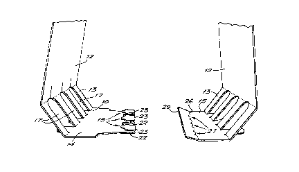
Figures 2a and 2b show perspective end views of
the interlocking arrangement of figure l before and
after connection,
Figure 3 is a part sectional plan view of an
assembled interlocking arrangement,
Figure 4 is a schematic ena view of the

CA 02202386 19s7-04-1o
WO96/l2656 PCT/GB95/024~8
-- 3
assembled interlocking arrangement of figure 3,
Figure 5 shows a blank for a carton
incorporating another interlocking arrangement
according to the present invention, ~nd
Figures 6a and 6b show perspective end views o~
the interlocking arrangement of figure 5 before and
after connection.
In figures 1 to 4 there is shown a blank 10 for
forming a sleeve-like carton for retaining three
articles. The blank 10 has a top 11, main side panels
12, sesondary side panels 13, a first base panel 14 and
a second base panel 15. Cut outs 16 are provided for
locating the tops of the articles and cutouts 17 are
provided for locating the bottoms of the articles.
These features are well ]cnown in the art of carton
5 manufacture.
The first base panel 14 is hingedly connected
to its associated side panel 13 by means of a fold 18
which connects the ends of the cutouts 17. The base
panel 14 is formed with three projecting flaps 19 each
20 having a leading portion 20. Immediately behind, that
is on the side nearest the cutouts 17, are laterally
projecting portions 21 which are angled laterally
outwards at 22 from a waist section 23 in the form of a
fold. Behind the waist, at 24, the flap again flares
25 laterally towards the widest parts 25 of the flap 19.
The widest parts 25 are just further from the waist 23
than the widest parts of the laterally projecting
portions 21, but are of a similar lateral width.
The second base panel 15 has a furthe~ fold 26
3 interspersed with three openings 27 in the form of
cuts. Th~ openings 27 are located at positions which
correspond to the positions of the flaps 19 on the
r first base panel 14 when the blank 10 is folded to make

CA 02202386 1997-04-lo
WO96/12656 PCTIGB95/02448
the carton. The lateral ends 28 of each opening 27 are
angled towards the free edge 29 of the base panel 15 in
the inward direction and then the central portion 30 of
the opening returns to the imaginary continuation of
the fold 26. The lateral width of the openings are
just marginally larger than the width of the laterally
extending portions 21 of the flaps 19.
The connection of the interlocking arrangement
will now be described. For the sake of convenience the
connection of only one fLap l9/opening 27 will be
described. The first step is to bring the two base
panels 14, 15 towards each other. The leading portion
and laterally projecting portions of the flap 19 are
folded upwards and back on the remainder of the flap
about the waist fold 23. Also the end of the second
base panel 15 is folded up slightly about the fold 26
thereby widening the op~ning 27. The flap 19, fold 23
0 first is then inserted through the opening 27. The
portions 21 are just able to pass through the opening
27 and when they have cleared the angled ends 28 of the
aperture 27 they tend to spring upwardly thus
preventing withdrawal of the flap 19 relative to the
opening 27 because the leading edges, now facing
backwards, of the laterally projecting portions 21
engage the angled ends 28 of the opening 27. At the
same time the central portion 30 of the opening is
located such that the leading portion 20 of the flap 19
does not clear the opening 27 remains held below the
second base panel 15. Further insertion of the flap is
not possible because the ends of the openings 27 engage
the widest parts 25 of the flap 19 at its join with the
rest of the base panel 14.
When the arrangement is fully interlocked the
interlock is generally flat. Such an interlock is,
therefore, particularly suitable for use with flat-

CA 02202386 1997-04-10
WO g6/12656 PCT/GB95102448
bottomed articles or containers, but can be used for
other articles or containers.
In the alternative version shown in figures 5
and 6 most features are the same as those in figures 1
to 4 and so have been given like reference numerals.
The principal difference is that the waist hinge 23 on
the flap 19 is not continuous but has a C-shaped cut 50
made centrally between two end folds 51. When the
leading portion 20 is folded back the tab 52 inside the
C-shaped -ut 50 projects forwardly of the hinge folds
51. When the flap 19 is interconnected with the
opening 27, the tab 52 remains projecting forwardly.
The article held at the location of the tab 52 tends to
press down on the tab thereby tending to encourage the
later~lly projecting portions 21 to raise further so as
to strengthen the engagement with the ends 28 of the
opening 27.
It will be appreciated that the shapes and
dimensions discussed above are examples of suitable
arrangements. Other pack sizes are of course equally
suitable and it is also possible that the interlock
could be provided on any paperboard article not
necessarily cartons for multipacks.
3o
-

Representative Drawing
A single figure which represents the drawing illustrating the invention.
Administrative Status

2024-08-01:As part of the Next Generation Patents (NGP) transition, the Canadian Patents Database (CPD) now contains a more detailed Event History, which replicates the Event Log of our new back-office solution.

Please note that "Inactive:" events refers to events no longer in use in our new back-office solution.

For a clearer understanding of the status of the application/patent presented on this page, the site Disclaimer , as well as the definitions for Patent , Event History , Maintenance Fee  and Payment History  should be consulted.

Event History

Description Date
Application Not Reinstated by Deadline 2003-10-17
Inactive: Dead - RFE never made 2003-10-17
Deemed Abandoned - Failure to Respond to Maintenance Fee Notice 2003-10-17
Inactive: Abandon-RFE+Late fee unpaid-Correspondence sent 2002-10-17
Letter Sent 1997-09-18
Inactive: First IPC assigned 1997-08-06
Inactive: IPC assigned 1997-08-06
Inactive: Notice - National entry - No RFE 1997-07-04
Inactive: Applicant deleted 1997-07-03
Inactive: Single transfer 1997-06-10
Inactive: Courtesy letter - Evidence 1997-05-13
Application Published (Open to Public Inspection) 1996-05-02

Abandonment History

Abandonment Date Reason Reinstatement Date
2003-10-17

Maintenance Fee

The last payment was received on 2002-10-04

Note : If the full payment has not been received on or before the date indicated, a further fee may be required which may be one of the following

  • the reinstatement fee;
  • the late payment fee; or
  • additional fee to reverse deemed expiry.

Please refer to the CIPO Patent Fees web page to see all current fee amounts.

Fee History

Fee Type Anniversary Year Due Date Paid Date
Basic national fee - standard 1997-04-10
Registration of a document 1997-04-10
MF (application, 2nd anniv.) - standard 02 1997-10-17 1997-09-24
MF (application, 3rd anniv.) - standard 03 1998-10-19 1998-09-30
MF (application, 4th anniv.) - standard 04 1999-10-18 1999-10-01
MF (application, 5th anniv.) - standard 05 2000-10-17 2000-10-05
MF (application, 6th anniv.) - standard 06 2001-10-17 2001-10-04
MF (application, 7th anniv.) - standard 07 2002-10-17 2002-10-04
Owners on Record

Note: Records showing the ownership history in alphabetical order.

Current Owners on Record
RIVERWOOD INTERNATIONAL CORPORATION
Past Owners on Record
NATHALIE BRIAND
Past Owners that do not appear in the "Owners on Record" listing will appear in other documentation within the application.
Documents

To view selected files, please enter reCAPTCHA code :


To view images, click a link in the Document Description column. To download the documents, select one or more checkboxes in the first column and then click the "Download Selected in PDF format (Zip Archive)" or the "Download Selected as Single PDF" button.

List of published and non-published patent-specific documents on the CPD .

If you have any difficulty accessing content, you can call the Client Service Centre at 1-866-997-1936 or send them an e-mail at CIPO Client Service Centre.


Document
Description 
Date
(yyyy-mm-dd) 
Number of pages   Size of Image (KB) 
Representative drawing 1997-08-25 1 8
Description 1997-04-10 5 203
Claims 1997-04-10 3 81
Drawings 1997-04-10 6 115
Abstract 1997-04-10 1 51
Cover Page 1997-08-25 1 48
Reminder of maintenance fee due 1997-07-03 1 111
Notice of National Entry 1997-07-04 1 193
Courtesy - Certificate of registration (related document(s)) 1997-09-18 1 118
Reminder - Request for Examination 2002-06-18 1 128
Courtesy - Abandonment Letter (Request for Examination) 2002-12-27 1 167
Courtesy - Abandonment Letter (Maintenance Fee) 2003-12-15 1 177
Correspondence 1997-05-13 1 39
PCT 1997-04-10 10 322