Language selection

Search

Patent 2202672 Summary

Third-party information liability

Some of the information on this Web page has been provided by external sources. The Government of Canada is not responsible for the accuracy, reliability or currency of the information supplied by external sources. Users wishing to rely upon this information should consult directly with the source of the information. Content provided by external sources is not subject to official languages, privacy and accessibility requirements.

Claims and Abstract availability

Any discrepancies in the text and image of the Claims and Abstract are due to differing posting times. Text of the Claims and Abstract are posted:

  • At the time the application is open to public inspection;
  • At the time of issue of the patent (grant).
(12) Patent: (11) CA 2202672
(54) English Title: SENSING TILT-COLUMN STEERING SHAFT TORQUE
(54) French Title: DETECTION DU COUPLE SUR COLONNE DE DIRECTION INCLINABLE
Status: Expired and beyond the Period of Reversal
Bibliographic Data
(51) International Patent Classification (IPC):
  • B62D 01/18 (2006.01)
  • G01L 05/22 (2006.01)
(72) Inventors :
  • PADULA, SANTO A. (United States of America)
(73) Owners :
  • EATON CORPORATION
(71) Applicants :
  • EATON CORPORATION (United States of America)
(74) Agent: BORDEN LADNER GERVAIS LLP
(74) Associate agent:
(45) Issued: 2002-09-24
(22) Filed Date: 1997-04-14
(41) Open to Public Inspection: 1997-10-30
Examination requested: 1999-02-12
Availability of licence: N/A
Dedicated to the Public: N/A
(25) Language of filing: English

Patent Cooperation Treaty (PCT): No

(30) Application Priority Data:
Application No. Country/Territory Date
08/641,456 (United States of America) 1996-04-30

Abstracts

English Abstract


A torque transducer has a circumferentially sleeve press fitted on the
user-tiltable portion of a vehicle steering shaft and disposed axially intermediate the shaft
support bearings. A stationary pickup coil is mounted over the sleeve and located with
respect to the sleeve by a second pair of bearings. In an alternate embodiment, two
circumferentially magnetized, axially spaced sleeves are utilized.


French Abstract

Cette invention concerne un transducteur de couple qui comporte un manchon magnétisé à polarisation circulaire monté à force sur la partie inclinable de la colonne de direction, entre les paliers-support de la colonne. Un bobinage statique de détection est monté sur le manchon et maintenu en place par une deuxième paire de paliers. Dans une autre variante de l'invention, on fait appel à deux manchons magnétisés à polarisation circulaire et axialement espacés.

Claims

Note: Claims are shown in the official language in which they were submitted.

WE CLAIM:
1. A tiltable steering column assembly for a vehicle comprising:
(a) lower support column means rigidly mounted on the vehicle structure;
(b) upper support column means tiltably mounted on the lower support column for
user selected pivotal movement about a generally horizontal axis transverse to
the vehicle;
(c) a lower steering shaft received through said lower support column;
(d) an upper steering shaft received through said upper support column means and journalled thereon for rotation in a pair of axially spaced bearings;
(e) swivel joint means interconnecting said upper and lower steering shaft and
operative for transmitting torque therebetween;
(f) a magnetic elastic active element fixedly attached to said upper shaft at a
location axially intermediate said pair of bearings, said element operative to be
torsionally strained by application of torque to said upper shaft; and
(g) electromagnetic means disposed on said upper column means adjacent said
magnetic elastic element and operative to detect torsional strain of said
element and provide an electrical signal indicative thereof.
2. The assembly defined in claim 1, wherein said magneto elastic element comprises at
least one circumferentially magnetized sleeve press-fitted onto said upper steering
shaft.
3. The assembly defined in claim 1, wherein said electromagnetic means includes a
coiled conductor.
- 5 -

4. The assembly defined in claim 1, wherein said magneto elastic active element
comprises a pair of axially spaced annular members.
5. The assembly defined in claim 1, wherein said magneto elastic element has an annular
configuration and is magnetized in the circumferential direction.
-6-
.

Description

Note: Descriptions are shown in the official language in which they were submitted.


CA 02202672 l997-04-l4
'' . '
95-CON-366 (LE)
SENSING TILT- COLUMN STEERING SHAFT
TORQUE
BACKGROUND OF TIIE INVENTION
The present invention relates to user adjustable or tiltable steering wheels employed
in passenger motor vehicles. Tiltable steering wheels currently employed in passenger motor
vehicles commonly employ a user releasable latch which enables pivoting of the steering
5 wheel about a horizontal axis transverse to the vehicle for moving the steering wheel to a
position facilitating passenger entry or exit from the driver's position in the vehicle. Tiltable
steering wheels have found wide-spread acceptance in passenger vehicles.
It has been desired to provide an electrical indication of the torque or steering effort
applied to the steering wheel by the vehicle driver and to employ such an electrical signal for
10 diagnostic and control purposes in the vehicle; one such application being control of a power
steering mechanism based, in part, upon a continuous electrical indication of the torque
applied to the steering wheel. However, in view of the swivel joint employed in the steering
shaft to ~comm~ t~ the tilting movement of the wheel, it has been found difficult to
provide a way or means of sensing the torque in such a tiltable steering wheel and yet provide
15 a reliable electrical signal indication of the applied torque to the wheel. It has long been
desired to IJa~ ulally find a way or means of providing an electric signal indicative of torque
applied to the steering wheel by the driver in a manner which is simple, reliable and low in
cost and easy to install on the steering wheel shaft during assembly of the tiltable steering
wheel mechanism in the vehicle during
2o SUMMARY OF TIIE INVENTION
It is an object of the present invention to provide an electrical signal çontim ","~ly
indicative of the torque applied to a vehicle steering wheel shaft by the driver during
I

.CA 02202672 1997-04-14
; '' .
95-CON-366 (LE)
operation of the vehicle; and, it is a further object of the invention to provide such an
electrical signal in a vehicle equipped with a tiltable steering wheel.
The present invention provides a ~ ;. . active element in the fomm of a
sleeve attached, and preferably press-fitted, onto the steering shaft between the joumal
5 bearings for the upper or tiltable portion of the steering shaft. A pick up coil is mounted over
the sleeve and is located by a pair of bearings which straddle the sleeve. In the preferred
practice, the sleeve is ~ ,U..~.~ , and, in an altemative ~i..lL _ ' a pair
of sleeves may be employed spaced axially on the steering shaft.
BRIEF DESCRIPTION OF TEIE DRAWINGS
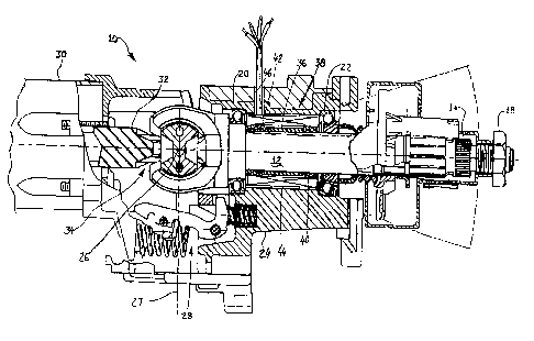
FIG 1 is a cross-section taken vertically through the steering shaft axis of a tilt wheel
steering, ' , and,
FIG 2 is an enlarged portion of a view similar to FIG. I of another embodiment of the
invention.
DETAILED DESCRIPTION
Referring to FIG. 1, a tiltable steering wheel assembly is indicated generally at 10 and
has an upper steering shaft 12 which has the upper end thereof splined at 14 and threaded for
receiving thereon a steering wheel hub (not shown) which is retained by nut 18. Upper
steering shaft 12 is joumalled in a pair of axially spaced bearings 20, 22 disposed in an upper,
tiltable, support column 24. The tiltable support column structure 24 is mounted on a lower
2 0 stationary support column 3 0 provided on the vehicle body structure (not shown).
The upper support column 24 pivots about an axis extending h( "~, and
of the vehicle and thus p~ ,uL to the picture plane in FIG. 1 and located
as denoted by reference numeral 26; it being understood that axis 26 is ~ di~,uL~ to the
dashed line 27 and intersects same. A user releasable latch mechanism indicated generally at
2 5 28 enables the user to latch the upper steering shaft 12 in any of several tilt positions
-- 2--
.

.CA 02202672 1997-04-14
95-CON-366 (LE)
indicated between the dashed outlines in FIG. 1.
Lower steering column section 30, which is rigidly attached to the vehicle's body
structure, supports a lower steering shaft 32 which is joumalled for rotation therein. Shaft 32
has its upper end connected to the lower end of upper steering shaft 12 by a suitable swivel
5 joint indicated generally at 34 such that the upper steering shaft 12 may be tilted about axis
26 with respect to lower shaft 32 but with torque ~ connection maintained
Referring to FIG. 1, upper steering shaft 12 has provided thereon and attached rigidly
thereto a torque sensor indicated generally at 3 8 which has a, .~ active element in
10 the fomm of a C;ll,UIl~~ '- ' annular sleeve 36 known in the art and which ispreferably press-fitted onto the shaft 12 ' bearings 20, 22. The magnetic sleeve36 is disposed between a pair of bearings 42, 40 disposed on axially opposite sides of the
sleeve 36 with the inner races of bearings 40, 42 registered on shaft 12. A magnetic pick up
coil 44 is registered on the outer races of bearings 40, 42; and, coil 44 has electrical leads
extending outwardly through support 24 in an aperture 46 fommed therein. The coil thùs
remains stationary and is located on and journalled on the upper steering shaft 12 for accurate
location with respect to the In~i7~d sleeve 36.
In operation when torque is applied to shaft 12 through steering wheel hub 16 by the
vehicle operator, the torsional strain in shaft 12 in the region between bearings 20, 22 is
20 transmitted to sleeve 36 causing disturbance ofthe lines ofthe magnetic field and the
resultant distortion creates an electrically detectable current in coil 44 which may be remotely
processed to indicate the torque applied to shaft 12.
Referring to FIG. 2, an altemative ~,...I,c ' of the torque sensor installation in a
tiltable steering wheel and is indicated generally at 138 and includes an upper steering shaft
112 joumalledinbearings 120,122assembledinuppersupportcolumnstructure 124which
is tiltably mounted on a lower support column. Sensor 138 has a pair of ~ ,u..~., I~y
" .~, 1;,. .1 l...,~,,.. 1,-~l ~l;~. rings 136, 137 press fltted on shaft 112 in axially spaced
An electrical pick up coil 144 is disposed thereover and joumalled on shaft 112
by suitable bearings 140, 142. In the t;---bOd;....,..L of FIG. 2 the coil 144 is operative to sense
- 3--

CA 02202672 1997-04-14
.
95-CON-366 (LE)
the differential torsional strain between the ~ ' elements 136, 137 in a malmer
similartothei bc" of FIG. 1.
The present invention thus provides a simple, reliable and low cost way of
~ a tiltable steering column assembly for providir~g an electrical signal indicative
5 of the torque applied to the steering shaft by the vehicle operator.
Although the invention has h."~ been described with respect to the illustrated
' - ' , it will be understood that the invention is capable of .",~ and variation
and is limited only by the scope of the following claims.

Representative Drawing
A single figure which represents the drawing illustrating the invention.
Administrative Status

2024-08-01:As part of the Next Generation Patents (NGP) transition, the Canadian Patents Database (CPD) now contains a more detailed Event History, which replicates the Event Log of our new back-office solution.

Please note that "Inactive:" events refers to events no longer in use in our new back-office solution.

For a clearer understanding of the status of the application/patent presented on this page, the site Disclaimer , as well as the definitions for Patent , Event History , Maintenance Fee  and Payment History  should be consulted.

Event History

Description Date
Inactive: IPC from MCD 2006-03-12
Time Limit for Reversal Expired 2005-04-14
Letter Sent 2004-04-14
Grant by Issuance 2002-09-24
Inactive: Cover page published 2002-09-23
Inactive: Final fee received 2002-07-15
Pre-grant 2002-07-15
Notice of Allowance is Issued 2002-02-15
Letter Sent 2002-02-15
Inactive: Approved for allowance (AFA) 2002-02-05
Letter Sent 1999-03-12
All Requirements for Examination Determined Compliant 1999-02-12
Request for Examination Received 1999-02-12
Request for Examination Requirements Determined Compliant 1999-02-12
Application Published (Open to Public Inspection) 1997-10-30
Inactive: First IPC assigned 1997-07-22
Inactive: IPC assigned 1997-07-22
Inactive: Filing certificate - No RFE (English) 1997-06-26
Letter Sent 1997-06-24

Abandonment History

There is no abandonment history.

Maintenance Fee

The last payment was received on 2002-03-25

Note : If the full payment has not been received on or before the date indicated, a further fee may be required which may be one of the following

  • the reinstatement fee;
  • the late payment fee; or
  • additional fee to reverse deemed expiry.

Patent fees are adjusted on the 1st of January every year. The amounts above are the current amounts if received by December 31 of the current year.
Please refer to the CIPO Patent Fees web page to see all current fee amounts.

Fee History

Fee Type Anniversary Year Due Date Paid Date
Registration of a document 1997-04-14
Application fee - standard 1997-04-14
Request for examination - standard 1999-02-12
MF (application, 2nd anniv.) - standard 02 1999-04-14 1999-03-18
MF (application, 3rd anniv.) - standard 03 2000-04-14 2000-03-17
MF (application, 4th anniv.) - standard 04 2001-04-16 2001-03-23
MF (application, 5th anniv.) - standard 05 2002-04-15 2002-03-25
Final fee - standard 2002-07-15
MF (patent, 6th anniv.) - standard 2003-04-14 2003-03-19
Owners on Record

Note: Records showing the ownership history in alphabetical order.

Current Owners on Record
EATON CORPORATION
Past Owners on Record
SANTO A. PADULA
Past Owners that do not appear in the "Owners on Record" listing will appear in other documentation within the application.
Documents

To view selected files, please enter reCAPTCHA code :


To view images, click a link in the Document Description column. To download the documents, select one or more checkboxes in the first column and then click the "Download Selected in PDF format (Zip Archive)" or the "Download Selected as Single PDF" button.

List of published and non-published patent-specific documents on the CPD .

If you have any difficulty accessing content, you can call the Client Service Centre at 1-866-997-1936 or send them an e-mail at CIPO Client Service Centre.


Document
Description 
Date
(yyyy-mm-dd) 
Number of pages   Size of Image (KB) 
Abstract 1997-04-13 1 11
Description 1997-04-13 4 153
Claims 1997-04-13 2 39
Drawings 1997-04-13 2 55
Representative drawing 2002-08-20 1 23
Representative drawing 1997-12-04 1 15
Abstract 2002-09-22 1 11
Claims 2002-09-22 2 39
Drawings 2002-09-22 2 55
Description 2002-09-22 4 153
Courtesy - Certificate of registration (related document(s)) 1997-06-23 1 118
Filing Certificate (English) 1997-06-25 1 165
Reminder of maintenance fee due 1998-12-14 1 110
Acknowledgement of Request for Examination 1999-03-11 1 178
Commissioner's Notice - Application Found Allowable 2002-02-14 1 164
Maintenance Fee Notice 2004-06-08 1 173
Correspondence 2002-07-11 1 25