Note: Descriptions are shown in the official language in which they were submitted.
CA 02202674 2003-O1-29
GRATE ASSEMBLY FOR A FLUIDIZ$D 8ED 80ILER
The present invention relates to a grate assembly for a
fluidized bed boiler to be used in particular in connection
with a layered fluidized bed or a circulating fluidized bed.
A grate assembly for a fluidized bed boiler is described in
Finnish patent application Fl-935455, wherein the grate
assembly consists at least partially of a number of spaced
apart parallel aporge pipes or the like extending side-by-side
in a substantially horizontal plane. The aporge pipes are
provided with means for supplying fluidizing air from within
the aporge pipes into the combustion chamber located above the
grate assembly. Coarse combustion products are discharged
through an aperture system situated between the aporge pipes
and into a receiver unit fitted below the grate assembly. At
least some of the sparge pipes are provided with a cooling
medium circulating system, whereby at least a part of the
cooling medium flow conduits of the system are arranged at the
upper edge of the aporge pipes to extend in the longitudinal
direction of the aporge pipes and at least partly laterally
limit the aperture system in the upper region of the sparge
pipes. The fluidizing air is supplied by way of tubular air
supply conduits which extend upward from the upper surface of
the aporge pipes. The air supply conduits are provided with
air nozzle apertures at the top.
Such a grate assembly has proven functional in practice, in
- particular with regard to cooling of the grate assembly. It
has been noticed in practice that it is advantageous for
cooling of the sparge pipes to position the coolant conduits
at least partially within an upper edge of the aporge pipes
and such that the respective coolant conduits of two adjacent
aporge pipes are located at the upper edges of the
intermediate aperture. An implementation of this type of a
cooling medium circulation system is shown in Finnish patent
application F1-935455. The edge area of the aporge pipe is
CA 02202674 1997-04-14
- 2 -
cooled, thereby reducing heat tension therein, which is
critical in view of the endurance of the sparge pipe. This
applies in particular to the corner area where the
substantially horizontal upper surface of the sparge pipe
meets the substantially vertical side wall of the sparge pipe,
i.e., the substantially vertical side edge of the aperture
system. Although this arrangement is advantageous for the
cooling of the sparge pipes, it is disadvantageous with
respect to the fluidizing air supply. Due to the placement of
the coolant conduits at the upper edges of the aperture
system, the fluidizing air supply must be placed farther away
from the aperture system, to the upper surface of the sparge
pipe, and perpendicularly to the longitudinal direction of the
aperture system. This is especially true when the cooling
medium circulation system is placed, at least partially,
within the upper,corners of the sparge pipes, because for
proper operation of the fluidizing process, the fluidizing air
has to be distributed evenly to the fluidized bed situated
above the grate assembly. In other words, the entire
fluidized bed has to be kept in a fluidized phase. Coarse
combustion product particles accumulate specifically in
regions of the fluidized bed wherein the air flow is
insufficient. If the air flow in the aperture system of a
grate assembly is insufficient, the aperture system may get
clogged due to no or insufficient air flow at the aperture
system, because larger sintered pieces may form from the
coarse particles produced at the aperture system, which pieces
can eventually block the aperture system, at least partly. To
overcome this problem, a solution must be found to either
provide an air supply which is smooth and sufficient for
maintaining a fluidized phase in the fluidized bed or by
increasing the air flow through the nozzles, for example, by
enlarging the nozzle apertures. However, this may result in
localized excessive air flow which may cause disturbances to
the fluidizing process itself. In any case, excessive air
flow also increases the energy cost of the process.
CA 02202674 2003-O1-29
- 3 -
The present invention seeks to reduce or overcome the above
described drawbacks by providing an improved cooled grate
assembly for use in fluidized bed boilers wherein sufficient
air flow is provided.
The present invention also seeks to ensure a smooth supply of
fluidizing air for maintaining the fluidized bed, in
particular in the area of the aperture system, in a cost
efficient manner and for preventing choking of the aperture
system.
According to one aspect of the present invention there is
provided a grate assembly for a fluidized bed boiler having a
combustion chamber located above the grate assembly and a
discharged material receiving unit located below the grate
assembly, which grate assembly includes at least one pair of
spaced apart parallel sparge pipes extending in a
substantially horizontal plane and provided with air supply
conduits for supplying fluidizing air from within the sparge
pipes into the combustion chamber. An aperture for the
discharge of coarse combustion products into the receiving
unit is provided between the sparge pipes of each pair of
pipes. At least one of the pair of parallel sparge pipes is
provided with a cooling medium circulation system having at
least one coolant conduit which is at least partly placed
within a surface of the respectively associated sparge pipe
and in the longitudinal direction of the sparge pipes at an
upper edge thereof to extend in a manner that it provides a
lateral limit to the aperture between the pair of sparge
pipes. The means for supplying fluidizing air include a
tubular air supply conduit extending from an upper surface of
the sparge pipe which channel is provided with at least one
air nozzle aperture, the air supply conduit extending
generally upwardly and towards the aperture in such a way to
be located at least partly vertically above the coolant
conduit.
CA 02202674 2005-05-09
- 3a -
According to another aspect of the present invention there is
provided a grate assembly for a fluidized bed boiler,
comprising: a plurality of sparge pipes arranged parallel in a
substantially horizontal plane and defining apertures
therebetween; a cooling medium circulation system, at least a
first part of the system being placed in an upper edge of the
sparge pipes so that the system provides a limit to an edge of
the aperture in the longitudinal direction of the sparge
pipes; a tubular supply channel extending from an upper
surface of the sparge pipe in a vertical direction and having
in its longitudinal direction at least one change of direction
for placing the upper part of the supply channel over top of
the first part of the cooling medium circulation system, the
channel having air nozzle apertures provided at its upper part
and providing fluidized air from the sparge pipes into a
combustion area above the grate assembly.
CA 02202674 2003-O1-29
- 4 -
In the following, a preferred embodiment of the invention will
be illustrated in more detail with reference to the
accompanying drawings, wherein:
Fig. 1 shows a schematic vertical cross-section
through a grate assembly in accordance with the
invention,
Fig. 2 shows a top plan view of a preferred embodiment
of the grate assembly in accordance with the
invention,
Figs. 3 to 7 show schematic vertical cross-sections through
other preferred embodiments of the grate
assembly in accordance with the invention.
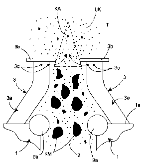
A preferred embodiment of a grate assembly according to the
invention as shown in Fig. 1 includes a number of sparge pipes
1 which are arranged in pairs of spaced apart parallel pipes
that respectively define an intermediate elongated discharge
aperture 2. This embodiment is especially advantageous in that
the aperture 2 between each pair of respectively spaced apart
parallel sparge pipes 1 of the grate assembly is kept from
clogging without using excessive amounts of fluidizing air.
By positioning and orienting the fluidizing air supply
conduits to be directed obliquely upwardly towards the
aperture 2, clogging can be prevented with reasonable amounts
of fluidizing air. A coolant conduit 9a belonging to a
cooling medium circulation system 9 of the grate assembly is
placed along each sparge pipe 1 at the upper edge thereof
which is directed towards the aperture 2. The coolant
conduits 9a extend parallel to the longitudinal direction of
the respectively associated aperture 2. A cooling medium,
such as water is used for the cooling of the grate assembly,
which medium flows through the coolant conduits 9a.
Fluidizing air is supplied from within the sparge pipes 1
CA 02202674 1997-04-14
- 5 -
(only partially shown in Fig. 1) through fluidizing air supply
conduits 3 to combustion chamber T and the fluidized bed LK.
Each fluidizing air supply conduit 3 is formed of a tubular
channel 3a and a substantially horizontal cover 3b closing the
upper end thereof. The cover 3b is preferably a rectangular
or square sheet having a diameter larger than the cross-
sectiona7, area of the tubular channel 3a. Air nozzle
apertures 3c through which fluidizing air is supplied are
provided in the wall of the air supply conduit 3a and below
the cover 3b. Fig. 1 shows an embodiment, wherein fluidized
bed material is removed from the fluidized bed of the
combustion chamber T through the apertures 2. As shown in
Fig. 1, coolant conduits 9a of the cooling medium circulation
system 9 are situated along the lateral edges of the aperture
system 2 and the sparge pipes 1 so that fluidizing air cannot
be directly supplied into the aperture from the top surface 1
of the sparge pipe 1. Rather, fluidizing air must be supplied
through the upwardly extending air supply conduits 3a.
Clogging of the aperture system is prevented by supplying
sufficient fluidizing air in the critical area immediately
above and at the top end of the aperture 2. Fig. 1 shows, in
broken lines, the so-called critical area KA at the top end of
the aperture system 2, in which critical area KA sufficient
fluidizing air velocity must be present to prevent sintering
and, thus, the formation of coarse combustion products which
may clog the aperture. In this embodiment, that is achieved
without using excessive amounts of fluidizing air which would
increase the energy cost of the process, but rather by
strategically placing the fluidizing air nozzles 3c and the
fluidizing air supply conduits 3a to ensure a continued
operation of the fluidizing process and low energy
consumption. This is achieved especially by the relative
position of the coolant conduits 9a and the fluidizing air
supply conduits 3 with respect to the aperture system 2. By
positioning the fluidizing air supply conduits 3 vertically
above the coolant conduits 9a, the air supply nozzles of the
coolant conduits 9a and, thus, the fluidizing air flow is
CA 02202674 1997-04-14
- 6 -
brought closer to the aperture 2. Furthermore, the aperture
system 2 is not excessively restricted by the coolant conduits
9a, which reduces clogging of the apertures.
The penetration depth of the fluidizing air exiting the air
supply nozzles can be adjusted by selecting specific air flows
and nozzle aperture sizes as well as specific air supply
pressures. The penetration depth is the depth of penetration
of the fluidizing air supplied via the fluidizing air nozzles
into the fluidized bed.
Removal of fluidized bed material is optimized by increasing
the cross-sectional area of the aperture system 2 downward
from the opening located adjacent the fluidized bed and
defined by the covers 3b. As a result, clogging of the
aperture system 2 by progressively agglomerating material KM
removed from the fluidized bed through the aperture system 2
is substantially prevented. The coolant conduits 9a are
preferably incorporated into the upper portion of the
respectively associated sparge pipe 1 by welding to the edges
of the substantially rectangular cross-section of the sparge
pipe 1 in such a manner that about 3/4 (three fourths) of the
outer periphery of the coolant conduit 9a forms part of the
outer surface of the sparge pipe 1, i.e. that the sheets
forming the upper surface la and the side wall of the sparge
pipe are connected to the coolant conduit 9a in a
perpendicular orientation. The particle size of the
agglomerating combustion products KM becomes progressively
larger during the passage thereof through the aperture system
but does not become larger in size than the transverse cross-
section of the aperture system. In accordance with the
invention, fluidizing air supply conduits 3 are connected to
the upper surface la of the sparge pipe 1 relatively far from
the aperture system 2, which is limited at the level of the
sparge pipes 1 by the coolant conduits 9a of the cooling
medium circulation system 9. However, by using the tubular
air supply conduits 3a, and orienting them towards the
CA 02202674 1997-04-14
_ 7 _
aperture 2, it is achieved that the air nozzles 3c can be
placed closer to the aperture system 2, than in conventional
arrangements. The air supply conduits 3a are positioned at
least partially vertically above the cooling medium
circulation system, i.e. the coolant conduits 9a. This
positioning of the air supply conduits 3a and the air nozzles
3c, relative to the aperture 2 obviates the requirement for
excessive air flows and provides energy economy. Optimal air
flow rates can be achieved by changing the air nozzle aperture
size. Thus, no excessive air flow is needed for the
maintenance of a fluid'ized bed and for continuous operation of
the process so that the energy cost will not be excessive
owing to the fact that the distance between the location of
the air nozzle apertures 3c and the critical area KA of the
fluidized bed are elongated.
Fig. 2 illustrates a grate assembly for a rectangular
combustion chamber T. In that embodiment, a conventional
cooling water circulation system is employed, the lower part
of which includes horizontal collector pipes 5 having a length
of each part of the wall structure. The collector pipes 5 are
connected to parallel, vertically rising ducts that form the
wall structure. The grate assembly is combined with the
cooling circulation system. Since a water-cooled boiler
assembly is, in view of its basic structure, known in the
field and is not directly related to the scope of the
invention, it is not described in more detail in this context.
In the embodiment of Fig. 2, the fluidizing air supply
conduits connected to the two opposing sparge pipes of an
aperture 2 are alternated in longitudinal direction of the
sparge pipes in a manner that a fluidizing air supply duct 3'
of a first sparge pipe 1' is situated between two adjacent
fluidizing air supply conduits 3" of a second sparge pipe 1",
at the opposite edge of the aperture system 2. Thus, an
optimal air supply is obtained since in the area of the
aperture system 2, powerful air jets can be arranged, which do
not substantially disturb one another but maintain a
CA 02202674 1997-04-14
_ g
sufficient air flow in the critical area KA (Fig. 1). The air
nozzle apertures 3c in this embodiment can be placed even
partially on top of the aperture system 2, because when the
opposite edge of the aperture system 2 is, at that location,
free of corresponding fluidizing air supply conduits 3, a
sufficient cross-sectional area of the aperture system 2 is
maintained in horizontal cross-section of the boiler plant.
Viewed from the top, the aperture system 2 is thus continuous
above the aperture system 2, with a horizontal zone being
provided at the level of the fluidizing air supply 3, which
horizontal zone has a pair of "imaginary" undulating edge
lines that twist back and forth at various locations in the
longitudinal direction of the aperture.
With particular reference to the preferred embodiments of
Figs. 3 and 4, the cooling medium circulation system 9 of the
sparge pipes comprises three pairs of coolant conduits 9a, 9b,
9c, which are placed in such a way that the uppermost pipes 9a
are placed at the upper corners of the rectangular sparge pipe
and, correspondingly, the lowermost ducts 9b are placed at the
lower corners of the rectangular pipe, whereas the central
ducts 9c are placed in horizontal direction in the side walls
lc of the sparge pipe. The sparge pipe 1 can comprise
internal supporting ribs 7, which can be partly diagonal. As
shown also in Fig. 2, a secondary structure for supplying
fluidizing air in the form of secondary air conduits 10 is
provided in the upper surface la of the sparge pipes 1, which
secondary conduits 10 are centred in transverse direction on
the upper surface la of the sparge pipe 1. The secondary
conduits 10 are alternated in longitudinal direction with
pairs of opposingly positioned fluidizing air supply conduits
3. The secondary air conduits 10 are situated centrally in
relation to the upper surface la of the sparge pipe and are
constructed as vertically oriented tubular air supply conduits
10a which extend directly upward from the upper surface la of
the sparge pipe. The secondary supply conduits 10 also
include a horizontal cover sheet 10b, similar to the cover 3b
CA 02202674 1997-04-14
- 9 -
of the air supply conduits 3 described earlier. Air nozzle
apertures lOc are provided below the cover sheet 10b.
In accordance with one aspect of the invention, the fluidizing
air supply conduits 3 include one or more changes of direction
in the longitudinal axis thereof as shown in Figs. 5 to 7. By
changing the direction of the conduits, the positions of the
air nozzles 3c can be controlled in the mounted condition of
the air supply conduits 3a. To achieved the different
directions in the longitudinal extent of the air supply
conduits 3a, the tubular air supply conduits 3a are either
bent (15a, 16a, cf. Figs. 5 and 6) or constructed of welded
together sections with obliquely cut ends (15b, 16b, cf. Figs.
6 and 7). In one embodiment, the lower portion 11 of the
tubular air supply conduit 3a, which is connected to the
sparge pipe 1, at the upper surface la thereof, is directed
obliquely upwards away from the vertical center line of the
cross section of the sparge pipe, towards the aperture system
2. In a corresponding manner, the upper portion 12 of the
tubular air supply conduit 3a is formed in a manner that it is
positioned substantially vertically.
Fig. 4 shows a structural alternative for the fluidizing air
supply conduits 3 in which the tubular air supply conduit 3a
is formed as a vertical tube which projects directly upwards
from the upper surface la of the sparge pipe and comprises at
its upper end a preferably horizontal, lateral extension 13
which projects in transverse direction, and a protective cover
sheet 14, whereby the extension 13 is a radially horizontally
extending, preferably rectangular box, which has vertical
walls 13a with air nozzles 13b. The apertured vertical wall
13a is placed at the location of the coolant conduits 9a and
adjacent the area of the aperture system 2, above the coolant
conduits 9a, at a height which is substantially defined by the
length of the air supply conduit 3a.
CA 02202674 1997-04-14
- 10 -
In the embodiments of Figs. 6 and 7, the fluidizing air supply
conduits 3 include a tubular air supply conduit, having two
bends whereby the tube at the joint with the upper surface la
of the sparge pipe 1 has a circular cross-section. This is an
important advantage for the machining of the aperture in the
upper surfaces of the sparge pipes 1 for the joint with the
air supply conduit 3a. In the lower portion 11 of the air
supply conduit 3a, a supplementary bent is formed, which
divides the lower portion 11 into two portions 11a, 11b, the
bottom one of which (11a) is vertical and the other is
directed obliquely upwards towards the aperture system 2. In
the embodiments, according to Figs. 6 and 7, the machining of
the circular aperture is easier than the elliptic form
required for the connection joint with the conduit 3a of the
embodiment of Fig. S wherein the upper part 11 of the air
supply conduit 3a is at an angle.
EXAMPLE
One preferred grate assembly, in accordance with the invention
for a fluidized bed boiler, is constructed as follows:
The bottom of the combustion chamber T is manufactured of
water-cooled box-shaped primary air channels. Each box-shaped
primary sparge pipe has a width of about 230 mm and height of
about 460 mm. Each pipe includes six coolant conduits 9a, 9b,
9c {cf. Fig. 3) having an outer diameter of 60.3 mm in a
manner that each corner of the rectangular cross-section of
the sparge pipe, as well as the central part of the vertical
side walls, includes a coolant conduit with a sheet structure
having a thickness of 6 mm extending therebetween. An
aperture having a width of about 170 mm is situated between
the sparge pipes, through which the coarsening, sintering
combustion products are discharged from the combustion chamber
and removed in a manner known in the art. The primary air
supply conduits are each welded onto the upper surface of the
CA 02202674 1997-04-14
- 11 -
rectangular sparge pipes in a manner that they are interlaced
over the entire area of the combustion chamber.
For ensuring sufficient primary fluidizing air supply,
altogether 680 conduits for supplying fluidizing air are
placed in a regular manner over the entire area of the bottom
of the combustion chamber. The distance between the air
supply conduits in the longitudinal direction of the sparge
pipe is about 180 mm. Ash produced during combustion of the
fuel is fine and is removed from the fluidized bed in the form
of flue dust, which is collected in a conventional combustion
gas cleaner known for use in combination with a boiler plant.
The combustion gas cleaner can be a cyclone separator or an
electrostatic filter. The coarse material (bottom ash) that
exists in the fluidized bed is removed from the combustion
chamber e.g. via removal funnels known in the art.