Note: Descriptions are shown in the official language in which they were submitted.
CA 02202955 1997-04-17
ISDN D CHANNEL RESTORATION WITHOUT LOSS OF
SIGNALING OR PACKET DATA
Technical Field
This invention relates to telecommunication switching systems having a
plurality of switching nodes, and, in particular, to the rapid backup of a
signaling
channel interconnecting two of the switch nodes.
Background of the Invention
In prior art telecommunications switching systems comprising a
plurality of stored program controlled switch nodes, it is well known that
when two
switch nodes are interconnected by a plurality of PRI links, to form these PRI
links
to a facility access service (FAS) group. Within a FAS group of PRI links, the
D
channels (which is used for signaling) in all but two of the PRI links are
utilized as
an additional B (bearer) channel. In the two remaining PRI links, one D
channel is
designated as the primary D channel, and the D channel of the second remaining
PRI
link is designated as the secondary D channel. In accordance with CCITT
specifications, if the primary D channel is lost, then, the two switching
nodes will
utilize the secondary D channel for signaling. The problem with the
utilization of
the secondary D channel in accordance with the specifications is that the
primary D
channel must time out which takes approximately 25 to 30 seconds before the
process is started to utilize the secondary D channel. Because of this delay,
all calls
that were in transit (e. g., being set up) or performing some feature
operation must be
terminated. In addition, any data call being performed on a logical link of
the
primary D channel must be terminated.
There are a number of reasons why the primary PRI link may be
disabled. One reason is that the primary PRI link is a wired link that has
been cut
accidentally. A second reason is that in a highly distributed system such as
illustrated in U. S. Patent 5,390,242 it is necessary to add and remove PRI
links
interconnecting switch nodes. At present, if calls are not to be terminated,
it is
necessary to wait until there are no calls being communicated on any of the
links
making up the FAS group. This is often done by indicating that each of the
links is
out of service. In general, this requires field personnel to work during the
early
morning hours when there is little activity on the system.
It is clear that a problem exists in the art with the present mechanism of
the secondary link backing up the primary link if the primary link should
fail. As
noted in the previous paragraphs, there are a variety of conditions under
which such
failures can happen on a routine basis, and it is not desirable to lose
routinely all
transient calls.
CA 02202955 1999-11-OS
-2-
Summary of the Invention
The foregoing problems are solved, and a technical advance is achieved by
an apparatus and method in a communication switching system having a plurality
of
switch nodes with each of the switch nodes responsive to a failure of the
primary
signaling channel that is providing the common signaling channel in a facility
access
service (FAS) group to immediately switch to the secondary signaling channel
of the
FAS group. Advantageously, this switching occurs quickly so that no calls are
dropped
within the FAS group. Advantageously, any logical links being communicated on
the
primary signaling channel are transferred to the secondary signaling channel
with no data
packets being irreplaceable lost.
A first physical object is established to control a physical protocol on the ,
primary signaling channel, and a second physical object is established to
control the
physical protocol on the secondary signaling channel. Further, a single
software object is
established to always control the first layer of software protocol on the
common
signaling channel whether that is the primary signaling channel or secondary
signaling
channel. When failure of the primary signaling channel is detected,
information for the
common signaling channel is routed from the second physical object to the
software
object, thereby preserving the common signaling channel. Advantageously, a
first
physical protocol identifier is assigned to the first physical object, a
second physical
protocol identifier is assigned to the second physical object, and a first
layer of software
protocol identifier is assigned to the software object. The procedure for
routing from the
second physical object to the software object involves identifying the second
physical
protocol identifier with the first layer of software protocol identifier.
Also, within the
ISDN protocol, the first and second physical protocol identifiers are
termination endpoint
identifiers, and the first layer of software protocol identifier is a
connection endpoint
suffix.
In accordance with one aspect of the present invention there is provided a
method of restoring signaling for a plurality of telecommunication links that
share a
common signaling channel, comprising the steps of: identifying a first
signaling channel
in a first one of the plurality of telecommunication links to provide the
common
signaling channel; identifying a second signaling channel in a second one of
the plurality
of telecommunication links to provide the common signaling channel upon the
first
CA 02202955 1999-11-OS
-2a-
signaling channel failing; setting up a first physical object to control a
physical protocol
on the first signaling channel and a second physical object to control the
physical
protocol on the second signaling channel; setting up a software object to
control
communication via the common signaling channel using a first layer of software
protocol; routing information for the common signaling channel from the first
physical
object to the software object; detecting a failure of the first signaling
channel; and
routing information for the common signaling channel from the second physical
object to
the software object in response to a detection of the failure whereby the
common
signaling channel is preserved.
In accordance with another aspect of the present invention there is provided
an apparatus for restoring signaling for a plurality of telecommunication
links that share
a common signaling channel, comprising: means for identifying a first
signaling channel
in a first one of the plurality of telecommunication links to provide the
common
signaling channel; means for identifying a second signaling channel in a
second one of
the plurality of telecommunication links to provide the common signaling
channel upon
the first signaling channel failing; means for setting up a first physical
object to control a
physical protocol on the first signaling channel and a second physical object
to control
the physical protocol on the second signaling channel; means for setting up a
software
object to control communication via the common signaling channel using a first
layer of
software protocol; means for routing information for the common signaling
channel from
the first physical object to the software object; means for detecting a
failure of the first
signaling channel; and means for routing information for the common signaling
channel
from the second physical object to the software object in response to a
detection of the
failure whereby the common signaling channel is preserved.
Other and further aspects of the present invention will become apparent
during the course of the following description and by reference to the
accompanying
drawings.
Brief Description of the Drawings
FIG. 1 illustrates, in block diagram form, a telecommunication switching
system embodying the inventive concept;
FIG. 2 illustrates a software architecture in accordance with the invention;
FIG. 3 illustrates, in block diagram form, greater detail of a switch node of
the telecommunication switching system of FIG. 1;
CA 02202955 1997-04-17
-3-
FIGS. 4 and 5 illustrate the internal data and control structures for the
physical and link layers;
FIG. 6 illustrates tables used by a virtual link object;
FIG. 7 illustrates, in flow chart form, the operations performed by the
link layer in setting up a FAS group; and
FIG. 8 illustrates, in flow chart form; the operations performed by the
link layer in transferring the communication in information from the primary
link to
the secondary link in accordance with the invention.
Detailed Description
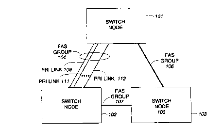
FIG. 1 shows a telecommunication switching system having a plurality
of switch nodes 101, 102, and 103. Advantageously, the switch nodes of FIG. 1
function as an integrated system to provide telecommunication services such as
those provided by an individual or a network of AT&T Definity~ Generic 2
Communications Systems. The switch nodes are shown as being interconnected by
FAS groups of PRI links. Each FAS group comprises a plurality of PRI links
such
as PRI links 109 through 112 of FAS group 104. The switch nodes of FIG. 1 are
arranged in a node hierarchy with switch node 101 being the highest switch
node of
the node hierarchy. The manner in which the node hierarchy initialization, and
dialing plan initiationization are performed is described in detail in U. S.
Patent
5,386,466 which is hereby incorporated by reference.
Each PRI link in FAS group 104 comprises 24 channels. If a PRI link is
utilized by itself, then the 24 channels of the PRI link are designated as
follows:
channel 0 is designated as the signaling channel/D channel and is utilized to
handle
the ISDN messages which are exchanged by the switch nodes. In addition, data
calls
can be set up on other logical links of the D channel. The remaining 23
channels are
designated as B channels and can be utilized for voice or data information.
Within a
FAS group, one of the PRI links is designated to carry the primary D channel,
such
as PRI link 109, and a second PRI link is designated to carry the secondary D
channel, such as PRI link 112. In both the primary and secondary PRI link, one
of
the 24 channels is designated as the D channel and the remaining 23 channels
can be
utilized for communicating voice or data inforTnation. The remaining PRI
links,
such as PRI link 111 of FAS group 104, utilize all 24 channels for the
communication of voice and data information.
As will be described in greater depth later, the software programs are
arranged in a software hierarchy with more general system operations being
performed as one moves from the lowest level of the software hierarchy to the
highest level. In accordance with the prior art which is the ISDN
specification, if
CA 02202955 1997-04-17
-4-
PRI link 109 fails, switch nodes 101 and 102 transfer the transmission of
signaling
messages from the D channel of PRI link 109 to the D channel of PRI link 112
after
approximately 25 to 30 seconds has elapsed. This transfer is controlled in
switch
node 101 and 102 by one of the higher software layers. Unfortunately, once the
transfer is accomplished, all transit calls being transported on FAS group 104
are
abandoned and must be reset up. In accordance with the invention, the transfer
from
the D channel of PRI link 109 to the D channel of PRI link 112 is accomplished
at
the lowest software layer and allows for the preservation of all calls that
are
communicated on the D channel of PRI link 109.
FIG. 2 illustrates the software architecture of the switch nodes of FIG. 1.
This architecture is based on the conventional OSI model modified to implement
the
ISDN protocol. Further modifications have been made to this model to
incorporate
the invention. Software layers 205 through 209 are described in U. S. Patent
5,386,466.
The principal function of physical layer 201 is to terminate physical
links. Specifically, physical layer 201 is responsive for maintaining physical
channels and for controlling physical sub-channels thereon. Physical layer 201
comprises a software portion and physical interfaces. Further, the software
portion
of physical layer 201 is responsible for the direct control of the physical
interface to
which physical links communicate PRI and BRI information terminate. Physical
layer 201 presents to link layer 212 physical sub-channels and physical
channel as
entities controllable by link layer 212. Since physical layer 201 is
terminating the
physical links, physical layer 201 determines when a D channel of the primary
PRI
link of a FAS group has failed because of the lost of framing on the channels
of the
D channel.
The primary function of link layer 212 is to assure that the information
transmitted over a physical channel is recovered intact and in the correct
order. This
is accomplished using another layer of protocol (referred to as the physical
packet
protocol) which allows multiple communications paths -- commonly referred to
as
logical links -- to be established on a given physical channel or a physical
sub-
channel communicating packetized data. These logical links are used to
identify and
process data being communicated between layer 212 and physical layer 201. In
ISDN Q.921, the protocol used is the LAPD packet protocol. Further, link layer
212
allows higher software layers to control physical layer 201 in an abstract
manner.
Link layer 212 uses a first layer of software protocol.
CA 02202955 1997-04-17
-5-
As seen in FIG. 2, link layer 212 is divided into link interface 202 and
link management 203. The reason for this division is set forth herein below.
It will
be helpful at this point to discuss the communication of ISDN signals over a D
channel to help readers who have only a rudimentary knowledge of the
communication of ISDN signals over a D channel. At link layer 212, a plurality
of
logical links is established on a D channel. Only one of these logical links
communicates ISDN control signals, and this logical link is referred to as a
logical D
channel (LDC). The LDC is identified by a logical D channel number (LDCN).
Link interface 202 does the majority of the functions performed by link
layer 212, including the establishment of logical links. Link management 203
identifies the various link interfaces for higher software layers. Further,
link
management 203 communicates information between the logical links and higher
software layers. In addition, link management 403 is responsive to a signal
from
physical layer 201 indicating that the primary D channel has lost framing to
switch
to the D channel of the secondary PRI link of a FAS group.
Network layer 204 processes information communicated on the LDCs
and terminates the ISDN Q.931 protocol. Hence, this layer is responsible for
negotiating the utilization of system resources for the termination or
origination of
calls external to a switching node. The network layer controls the allocation
of
channels on an interface on which a call is being received or set up. In
addition,
network layer 204 determines the primary and secondary D channels of a FAS
group. For example, if switch node 102 receives a call from switch node 101
via
PRI link 111, network layer 204 of switch node 102 negotiates with its peer
layer
(the corresponding network layer 204 in switch node 101 ) in order to obtain
allocation of a D channel in PRI link 111. This negotiation is carried out
using
standard ISDN Q.931 messages such as the call setup message via the LDC setup
on
the D channel of PRI link 109 (assuming that this is the primary PRI link of
FAS
group 104). Greater detail on the manner in which network software layer 204
functions with respect to setting up calls is set forth in U. S. Patent
5,386,466.
FIG. 3 illustrates, in block diagram form, the software architecture of
FIG. 2 as implemented in switch node 102. Software layers 203 through 209 are
implemented on the main processor of switch node 102 which is node processor
301.
Specifically, the software layers down through the link management portion of
the
link layer are realized by software layers denoted as 316 through 310 in node
processor 301. The link interface portion of the link layer is implemented by
a
software module node in processor 301 designated as local angel 302.
CA 02202955 1997-04-17
-6-
The physical layer is jointly implemented by hardware and software.
Specifically, the hardware portion of the physical layer for switch node 102
is
implemented by interfaces 304 through 307. The software portion of the
physical
layer is performed by local angel 302.
To understand the operation of FIG. 3 consider the following example.
First, consider the manner in which FAS group 104 is established. It is
assumed that
PRI link 109 is the first PRI link between switch node 101 and switch node 102
to be
initialized with PRI link 112 being the second. When PRI link 109 is
initialized,
interface 304 and its corresponding interface in switch node 101 perform the
necessary initial operations. One of these operations is the establishment of
termination endpoint identifier (TEI) 412. Both the hardware and software
operations upon a PRI link being initialized are set forth in detail in U. S.
Patent
5,386,466. During these operations, node numbers are exchanged between switch
nodes 101 and 102, and switch node 102 determines that switch node 101 is
higher
in the hierarchy. After initialization, the link interface layer being
executed in local
angel 302 will have terminated and denoted two logical links in D channel 421.
The
higher level designation for the logical links is a connection endpoint suffix
(CES)
which is shown on FIG. 4 as CES 400. CES 400 and TEI 412 are logically
connected to allow the communication of information. Link management 310 of
FIG. 3 is responsive to the creation of CES 400 to create two logical links
that
terminate on virtual link object 431. Connection endpoint identifier 404 (also
referred to as service access point identifier (SAPI) 0) is made operational
on logical
link 0 of D channel 421, and link management 310 establishes LAPD protocol 422
on this link and utilizing buffers 401. This logical link with corresponding
protocol
buffers is identified to network software layer 311 as LDCN 406. In addition,
link
management layer 310 establishes a communication link with its counterpart in
switch node 101 on logical link 63 which is identified as CEI 403 (also
referred to as
SAPI 63) with the companion software entity LAPD 423 and buffers 402. As
described in the aforementioned U. S. Patent, network software layer 311
associate
call records with LDCN 406 for any calls that are set up on PRI link 109.
Finally,
link management software layer 310 marks PRI link 109 as communicating the
primary D channel for any FAS group that may be started.
Next, assume that PRI link 112 is initialized between switch node 101
and switch node 102. When this PRI link is initialized, the link interface
software
being executed in local angel 302 establishes logical links on D channel 420,
establishes TEI 417, and identifies the TEI 417 to CES 410. In response to the
creation of CES 410, link management software layer 310 establishes virtual
link
CA 02202955 1997-04-17
_7_
object 432 which comprises elements 408-411, 424 and 426. Link management 310
also marks in management information base 308 that PRI link 112 is the
secondary
PRI link. At this point, link management software layer 310 identifies PRI
link 109
and PRI link 112 as comprising FAS group 104. Note, that link management
software layer 310 does not identify CEI 411 as a SAPI 0 link to network
software
layer 311. Hence, network software layer 311 does not create an LDCN for this
new
SAPI 0 link. Even though logical links 0 and 63 are set up on D channel 420,
no
messages are transmitted over these logical links while the primary PRI link
I09 is
properly functioning. Consequently, buffers 407 and 408 are empty. When PRI
link
111 and subsequent PRI links of FAS group 104 become active, no logical links
are
established on what would be the D channel of these new PRI links, but rather,
that
channel is used as another B channel. All calls that are set up on FAS group
104 are
controlled by LDCN 406 as illustrated in FIG. 4.
In accordance with the invention, consider now the operations
I S performed by link management 310 upon PRI link 109 becoming disabled.
Interface
304 detects the loss of framing on D channel 421 as soon as PRI link 109
becomes
disabled. Interface 304 reports this loss to link management software layer
310 via
the link interface software. Link management 3I0 then directs the link
interface
software to communicate information between TEI 417 (which terminates D
channel
420) and CES 400 rather than CES 410. The information in buffers 401 and 402
is
still valid and has not been lost. Any packets which were in transit via PRI
link 109
during the period of time that it became disabled will be recovered by the
LAPD
protocols 422 and 423 in conjunction with the LAPD protocols in switch node
101.
Switch node 101 performs the same operations as performed by switch node I02.
The result is illustrated in FIG. 5. Importantly, network software layer 3I 1
never
becomes aware of the change from D channel 42I to D channe1.420; hence,
network
software layer 311 does not drop any calls. Note, that the higher software
layers 312
through 316 are also totally unaware of the interchange of D channels.
FIG. 6 illustrates the tables that comprise CEI 403, CEI 404, and CES
400 as shown on FIG. 4. Within CEI 403 and CEI 404, the CES 611 and CES 601
entries in tables 608 and 618 respectively, define whether CES 400 or CES 410
of
FIG. 4 is being utilized. Within CES 400, channel number 622, interface number
623 and TEI 624 entries in table 628 define whether TEI 4I2 or TEI 4I7 of FIG.
4 is
being utilized for communication of information. As previously described, when
recovery is made from failed primary PRI link I09 to the secondary PRI link
112,
CES entries 601 and 61 I are changed to reflect that TEI 417 is being utilized
rather
than TEI 412. The channel number entry defines the channel being utilized
which in
CA 02202955 1997-04-17
_g_
the case of a PRI link is channel 0. The interface number defines the physical
interface, i.e., interface 304. In tables 608, 618, and 628 the remainder of
the entries
are defined in U. S. Patent No. 4,386,466 which is hereby incorporated by
reference.
FIG. 7 illustrates the operations of the link layer in setting up a FAS
group and in processing the initialization of a new PRI link. Decision block
701
determines if a new link is initializing. If the answer is yes, block 702
establishes a
TEI for this new PRI link. Decision block 703 then determines if there is
already a
PRI link going to the same destination switch node. If the answer is no, block
704
establishes the CES, and block 706 initializes the new link as a sole PRI link
before
transferring control back to decision block 701.
Returning to decision block 703, if the answer is yes, decision block 707
determines if a FAS group has already been established. If the answer is yes
in
decision block 707, block 711 establishes the new PRI link using all of the
channels
as D channels before returning control back to 701. If the answer in decision
block
707 is no, block 708 establishes the CES, and block 709 initializes the new
link as a
secondary link.
Returning to decision block 701, if the answer is no, control is
transferred to decision block 802 of FIG. 8. FIG. 8 illustrates the operations
performed by the link layer when a PRI link loses framing. If the answer in
decision
block 802 is no, block 803 processes the stimulus received by the link layer
in the
normal manner. If the answer in decision block 802 is yes, decision block 804
determines if the link is in a FAS Group. If the answer is no in decision
block 804,
block 806 performs normal processing for a link that has lost framing. If the
answer
in decision block 804 is yes, decision block 807 determines if the primary
link of the
FAS group has lost framing. If the answer is yes in decision block 807, block
808
establishes communication between the TEI of the secondary link and the CES of
the
former primary link. This result is illustrated in FIG. 5. Block 809 then
marks the
secondary link as the primary link in the management information base 308 of
FIG. 3 before transferring control to decision block 813.
If the answer in decision block 811 was yes indicating that the
secondary link had lost framing, control is transferred to decision block 813.
Decision block 813 determines whether it is possible to establish a new
secondary
link one of the other links presently in the FAS group. A new secondary link
can
only be established if channel 0 of one of the other links is idle so that
this channel 0
can be designated as a D channel rather than a B channel. If the answer is no
in
decision block 813, block 814 performs normal processing. If the answer in
decision
block 813 is yes, block 816 establishes a new secondary link for the FAS group
CA 02202955 1997-04-17
-9-
before transferring control back to decision block 701 of FIG. 7.