Note: Descriptions are shown in the official language in which they were submitted.
CA 02203270 1997-04-21
W Og6/12977 ~CTAUS95/10932
FORMATION DEMSITY TOOL FOR USE IN CASED AND OPEN HOLES
FIELD OF THE INVENTION
;.
This invention relates generally to oil and gas well logging tools. More
particularly, this invention relates to tools for measuring rock formation density
through the use of ~.n~ rays. Still more particularly, this invention relates to an
illl~l~)~ed density tool that may be used in cased holes as well as open holes.
BACKGROUND AN]D SUMMARY OF THE INVENTION
Logging tools for measuring the formation density in open holes are well
known. Cu~re.~Lly-available "open-hole" density logging tools norrnally include a
~;~mm~ ray source, typically cesillm-137, and two detectors--a near detector and a
far detector. Open-hole density tools have two detectors to colll~ellsate for mn(1r~ke
(i.e. a layer of solid material consolidated from drilling fluid that norrnally lines an
open borehole) and standoff (i.e. the ~ t~nre between the tool and the side of the
borehole). (l~mm~ rays are contiI:uously elnhte-l from the source and propagate out
through the m~ ke and into the forrnation. The electron density of the formationis calclll~t~rl based on the count rate or illtel~iLy of the g~mm~ rays that are received
at the detectors after passing through the mll~c~ke and formation.
In addition to employing radioactive sources for g~mm~ rays, it is anticipated
that density tools will employ accelerators, or more specifically electron
accelerators, as g~.n.ll~ ray sources even though such accelerators are not ~ nLly
available. In tools employing accelerators, the detectors will not n.ocess~rily detect
and/or calculate ~mm~ ray count rates because most accelerator l~si~n~ generaterelatively huge amounts of ~mrn~ rays for brief, illL~lllliL~llt periods of timeresulting in large qll~nti~ies of g~m m~ rays eng~ging the detectors within a relatively
short period of tirne. Thelefore, it may be more feasible to detect and measure the
SIJBSTITUTE SHEET (RULE 26)
CA 02203270 1997-04-21
WO 96/12977 PCr/US9S/10932
s of the ~mm~ rays rather than the count rate or the rate at which ~
rays engage ~e detectors. The detectors would generate voltage signals proportional
to the i~knsiLies of the rletecte~l g~mm~ rays as opposed to count rate signals.
In general, a layer of m~ k~ exists along the outer periphery of the
borehole. The illl~iLy signals from the near and far detectors are combined to
provide a me~ure of the for_ation density that is essenti~lly independent of this
mll~lc~ke if the thickn~ss of the mlldr,~ke is within a limiterl range. This is possible
when the spacings and collim~tions chosen for the two del~clol~ result in
Subs~ lly ~lirrel~ sensitivities to the mll-lr~ke and formation. The thickn~ss of
the m~ r~ke that can be collllJensated for is limite-l by the spacing between the near
detector and the g~mm~ ray source and by the collimation of the near detector. Alonger spacing between the g~mm~ ray source and the near detector enables more
mll-lr~ke to be penetrated by the g~mm~ rays and therefore enables the tool to
co~ nsate for thicker mllt1c~ke. However, greater spacing between the ~mm~ ray
source and the near detector reduce the contrast between the near and far detector
sensitivities to mll~lc~ke and the formation, thereby reducing the quality of the
density me~ rement.
However, the two detector density logging tools are limited in their use in
that they are unable to provide an accurate formation density when used in a cased
hole. Specifically, while the currently available two detector densi~y tools can
compensate for ml~ ke, they are unable to compensate for the casing and cement
and are therefore unable to accurately late the formation density in a cased hole.
The g~mm~ ray detectors consist of sodium iodide crystals connected to
photomultiplier tubes. These devices are commercially available and well known in
the art. When ~mm~ rays interact in the sodium iodide crystal, they produce light
which is converted by the photomultiplier tube into an electronic signal. These
signals are amplified to produce voltage pulses that are proportional to the energy
SUBSTITUTE SHEET (RULE 26~
CA 02203270 l997-04-2l
WO 96/12977 PCI~/US95/10932
deposited in the crystal. These vo]tage pulses may be counted to ~ete~ the grossnumber of ~""~ rays rl~tPCt~ per second or they may be sorted by amplitude to
delellllille the number of ~;~mm~ rays ~l~tecte~l per second ln various energy ranges.
- The later technique is common in open-hole logging, as described in the paper "A
New Approach to Determinin~ Co~ sated Density and Pe Values with a
Spectra-Density Tool", presented by G.L. Moake at the Annual SPWLA Logging
Symposium in ~irll~nrl, June 16-19, 1991.
Typical t-wo detector densi~ty tools are decentralized with a l)uw~ g or
caliper device so that the deteclor~ and the source are pushed up ~g~in~t the side of
the borehole. The decentr~ ti(ln of the tool against the side of the borehole
subst~nti~lly precludes the g~mm~ rays from prop~ting u~rd through the
drilling fluid and therefore the effect of the drilling fluid on the density m~cllrement
lSIllllllllll,~
However, as noted above, the two detector density tools cannot adequately
function in cased holes bec~ e they are unable to compensate for the casing and the
cement. In short, too many variables are ~les~ in order to accurately calculate the
formation density. Specifically, in order to probe the formation, the g~".",~ rays
must exit the tool, pass through the casing and cement and scatter in the formation
before passing back through the cement and the casing to finally reenter the tool to
be ~ietecterl Thus, instead of just a mll-le~ke correction as in the case of open holes,
a cased hole density tool must be able to correct or col~ellsate for the cement and
casing which are both more formi(1~hle a correction than a layer of m~ c~ke
because of the relatively high 11en~ilies of metal casing and thick amounts of cement
(i.e. fewer ~;~mm~ rays are able to penetrate the casing and cement to reach the near
detector).
Occasionally, open hole den~ity tools are used to run cased hole density logs.
The information provided by open hole density tools in cased holes is accurate in
SUBSTITUIE S~IEET (RULE 26)
CA 02203270 1997-04-21
W O96/12977 PCTrUSg5110932
only a limite-l number of cases, primarily when the cement thickn~s.s is quite smalI
or no cement is present. This can occur on the low side of deviated wells where the
casing may very well be resting ~ in~t bare formation or only a small amount of
cement will be disposed behind a casing. Typically, open hole density tools employ
S a ~mm~ source in the form of cont~inPd ce~ m-137 which produces 0.662 MeV
~mm~ rays. The amount of cement that can be corrected for is limited by the nearor "first" detector. Typically, these near detectors can correct for only about 0.75
inches of m~ k~ in an open hole and there~l~ it is easy to see why these tools
are ineffective in co~ tin~ for steel casing, which is normally 0.36 to 0.50
inches thick in combination with a layer of cement disposed behind the casing. In
any event, even dangerously thin casing is much denser, and therefore more
effective at blocking the passage of g~mm~ rays, than mll~lc~ke.
As the ~mm~ rays pass through the casing, cement and formation, they are
scattered and absorbed by these materials. The primary scattering interaction iscalled Co~ oll scattering and is caused by electrons in the casing, cement and
formation. Coll.pt()ll scattering tends to reduce the energy of the ~mm~ rays that
are scattered until their energy is so low that the g~mm~ rays are absorbed by
electrons through an interaction called photoelectric absorption. Thus, if the density
of electrons in the casing, cement and formation is high, fewer electrons will make
it back through the formation, cement and casing to be detected in the tool. In short,
the number of detected ~mm~ rays varies inversely to the density of electrons inthe various materials through which the g~mm~ rays must pass. Since the density
of electrons is directly related to the density of the material being measured, the
number of detected g~mm~ rays will also depend strongly on the density of the
casing, the density of the cement and the density of the fo~ aLion.
Two other physical processes that dominate the scalleling and absorption of
g~mm~ rays are known as coherent scattering and photoelectric absorption, both of
which are highly dependent upon the composition of the material. Those skilled in
SUBSTITUTE SHEET (RULE 26)
CA 02203270 1997-04-21
W Og6/12977 ~ 5/10932
the art commonly represent the strength or effect of the coherent scattering andphotoelectric absorption inter~-~ti-~n.c relative to the strength of Col"~t~ll scattering
with the variable Pc~ Thus, the a~lount of ~mm~ rays rletectell at the tool will also
depend on the Pe of the casing, the Pe of the cement and the Pe of the r~lu~lion. Of
course, the ~l~tecte~ mm~ rays will also depend on the t~icknPss of the casing and
the thirlrn~s~ of the cement.
As stated above, the perform~n~e of the tool will also depend slightly upon
the density of the borehole fluid. Ho~ver, density tools are ctlmmnnly
decentralized in the borehole, m~nin~i that the tool, including the source and
detectors is pushed up ag~inct the side of the borehole. In that manner, there is very
little borehole fluid through which the g~mm~ rays must pass in order to be ~let~ctecl
at the tool. Further, since the borehole fluid properties are usually known and in any
event can be tested at the surface, small correction factors based on the knowledge
of the borehole fluid properties can be easily ltili7.o-l.
Accordingly, there are eigh~ variables that affect the response of the tool: thedensity of the casing (p5); the thirL-n~ss of the casing (tS); the Pe of the casing: the
density of the cement (Pc); the Pc of the cement; the thickn~s.s of the cement (tc): the
formation density (pf); and the Pe of the formation. However, all but three
independent combinations of variables can be accounted for prior to measurement.
First, c~cin~c tend to be made of the same material, namely carbon steel.
Therefore, c~cin~c tend to have about the same density (p5) and Pe Thus the density
and Pe of the casing are known.
Second, the Pe of most cements is a negligible value because the low energy
~mm~ rays that are sensitive to the Pe of the cement are blocked by photoelectric
absorption that occurs within the casing. Accordingly, only the density and thickn~ss
of the cement are important. Further, the variations in the ihlL~l~iLy signal of
SU~STITUTE SHEET (RULE 26)
CA 02203270 1997-04-21
WO 96/12977 P~T/US9S/10932
letect~ rays at the tool due to the presence of cement behind the casing can
be thought of as changes to ~e il~ xily signal that would be obtained where no
cement is present at all. The cement can be thought of as a local sllbstit~ltion for
formation. That is, it is reasonable to expect the int~n.~ity signal to vary with the
dirrerellce between the formation density and the cement density as well as with the
cement thickn~s. If either the contrast in the densities of formation and cement or
the cement thickn~s is zero, then the effect of the cement is also zero. Thel~fole,
the effect of the cement on the tlet~cted inLensiLies at the tool will depend primarily
on the following expression:
( Pf- Pc) tc
where pfiS the folmation density, Pc is the c~meIlt density and tc is the cement~hirknPcs. The expression ( pf- PC)tC can be treated as one variable. Similarly, the
1~ efiect of the casing on the l~t~cte~ s at the tool will be proportional to the
following expression which also can be treated as one variable:
( Pf- P~ ts
where p5 is the density of the casing, tS is the thickness of the casing and pfiS the
formation density.
Further, the Pe of the formation can also be neglected because Pe is a much
lower value for high energy g~mm~ rays than for low energy g~mm~ rays. In other
words, the effect of coherent scattering and photoelectric absorption is very low for
high energy g~mm~ rays; in contrast, the effect of coherent scattering and
photoelectric absorption is relatively ~ignific~nt for low energy g~mm~ rays.
However, any ~mm~ rays that become low energy g~mm~ rays in the formation
are unlikely to penetrate the cement and casing before being det~cte~ by the tool.
Thus, the measured intensity at the tool will not depend significantly on the Pe of
--6-
SUBSTITUTE SHEET (RULE 26)
CA 02203270 1997-04-21
W O 96112977 PCTAUS9~110932
the forrnation.
Thele~t;, in light of the above, there are only three independent variables
- that .ci~nifir~ntly affect the m~cllred intensities: the density of the formation (pf);
(pf - p~) tc; and (pf - p5) tS. Bec~llse there are three unknown variables, three
independent i"l~"~ s must be measured in order to determine the formation density
in a cased hole. Further, ~csllmin~ a casing density (p5) and a cement density (p~,
one can ç~lrlll~t~ the casing thickn~ss (tS) and cement thir~n~ss (tc) respectively.
Accordingly, it would be highly desirable to provide a density logging tool
with at least three detectors that would be capable of m~cllring the formation
density in a cased hole as well as cement thickn~ss and casing thicknlocc. An
effective cased hole density logging tool in combination with akeady existing cased
hole neutron logging tools would provide an effective means for fintl;n~ additional
gas reserves behind existing cased holes. Further, an effective cased hole density
tool would also provide important illfollllation regarding formation evaluation behind
the casing. It is further coll~ lated that an improved cased hole density logging
tool could also prove useful in open holes.
An improved tool for measuring formation density in cased or open holes is
provided in the form of a housing that accommodates a ~mm~ ray source and at
least three ~letectors. The g~mm~ ray source is spaced axially from the first, second
and third detectors. The first or near detector is axially spaced from the ~mm~ ray
source by a tlict~nre defined as a first spacing. The first spacing and collim~tion for
2~ the first detector are ~iesign~l sO that the g~mm~ rays ietecte~ at the first de~ector
are those ~mm~ rays that are scattered ~lhllalily by the casing. In short, the first
tletector primarily detects or ~ler~Le,llially detects g~mm~ rays scattered through the
casing.
A second or middle detector is spaced axially farther away from g~mm~ ray
-7--
SUBSTITUTE SHEET (RULE 26)
CA 02203270 1997-04-21
WO 9C/12977 PCT/US9S/10932
source than the fllSt detector. The second detector is spaced from the ~mm~ ray
source by a tlitt~nre defined as a second spacing. The second spacing and
collim~ticn for the second detector are ~iesi~n~1 so that the ~mm~ rays ~letecte~l at
the second detector will be those that are p~ lalily scattered by the casing and t,he
S cement Finally, a third or far detector is spaced axially farther away from the
~mm~ ray source than both the first and second detectors by a (lict~n~e defined as
a third spacing. The third spacing and collim~tion defined by the third detector are
~esignPo' so that the g~mm~ rays ~letecterl at the third detector are those primarily
scattered from the casing, cement and formation. It is this third detector that enables
the tool to m~tllre formation density while the first and second detectors primarily
enable the tool to COll~CL for casing and cement. However, the second detector can
be used to me~cllre formation density in the absence of cement.
Preferably, the detectors are shielded by a high density matelial that prevents
detection of ~,.""~ rays that are simply travelling up through the tool. A pathway
or void in the shielding is provided in the form of a collimation channel which
extends from the detector through the tool and le~nil~ s at the outside surface of
the tool. The collim~tion ch~nn~l.t are specifically (lesi~n~fl for the purpose of each
detector. Specifically, the near or first detector will have a collimation that is aimed
at a steep angle with respect to the casing so that the first detector will detect
~mm~ rays that are scattered through all of the casing. The second or middle
detector will have a collimation that is directed at a shallower or more perpendicular
angle with respect to the casing because the second detector is intended to detect
g~mm~ rays scattered through all of the cement as well as the casing. Finally, the
third or far detector will have a wide collim~tion channel which is directed
subst~nti~lly perpendicular to the casing due to the tli~t~nr.e of the third detector
from the source. Bec~ e ~mm~ rays ~etectel1 at the far detector must pass
through the casing, cement, formation before p~csing back through the cement andcasing, the st~ti~ti~l probability of this event happening is smaller than for the first
and second detectors and therefore a wider collim~tion channel is required for the
SUBSTITUTE St IEET (RULE 26)
CA 02203270 1997-04-21
W O96112977 1~~ sllo932
third detector.
It is also ~nticir~te~ that a high energy ~mm~ ray source such as cobalt-60
which provides 1.173 a~d 1.333 MeV g~mm~ rays will be ntili7erl Other g~mm~
S ray sources, such as c~sillm-137 which provides only 0.662 MeV ~mm~ rays or
accelerator sources such as an electron accelerator could also be used. However, the
spacing between the third or far ~1etectQr and the ~ ray source will be longer
than the conventional spacing bet~een the g~.. ~ ray source and far detector in a
open hole tool and th~,erul~ a source which emits higher energy ~,;1llllll~ rays (i.e.,
1.173 and 1.333 MeV) will provide a higher i"~ iLy at the far 1etectQr.
The present invention also lends itself to an improved method of measuring
formation density behind casing as well as cement thickness and casing t11icknPss.
Specifically, the casing, cement al.ld forrnation are irr~ te~l with ~mm~ rays.
~J~mm~ rays are rletect~ at a first ~l~t~ctor spaced a first axial tli~t~nre from the
~,~mm~ ray source. A first h~ siLy is c~lc~l~tecl for the first detector. G~mm~ rays
are also detected at a second ll?tector disposed a second axial li.ct~nre from the
p~mm~ ray source. The second ~l~tector being disposed farther from the source than
the first detector. A second illLe~ y is calc~ te~1 for the second detector. ~T~mm~
rays are also detected at a third detector spaced a third axial ~ t~nre from theg~mm~ ray source. The third detecf.or ia spaced farther from the source than both
the first and second r1etectors. A third illlellsiLy is calc~ te-l for the third detector.
An estim~tPrl formation densit~y, cement thicknP~s and casing thitL-n~c.~ is then
calclll~tP~ based on the first, second and third intensity signals and by assuming
constant values for the density and Pe of the casing, negligible values for the Pe of
the cement and the Pe of the formation and using a correction factor for the borehole
fluid.
It is thererol~, an object of the present invention to provide an hll~io./~d
forrnation density tool for use in cased holes.
SUBST~TUTE SHE~T (RULE 26)
CA 02203270 1997-04-21
WO 961129M P~ J~95tlOg32
Another object of the present invention is to provide a logging tool which is
capable of m~ .. . ing formation density while compenc~tin~ for the effects of casing
and cement.
Another object of the present invention is to provide an improved three
detector follllalion density tool.
Another object of the present invention is to provide an improved method for
measuring fo~ Lion density behind casing.
Another object of the present invention is to provide an improved g~mm~ ray
density tool capable of mt?~llring cement thickness and casing thickn~cs
Yet another object of the present invention is to provide an improved
formation density tool that may be used in both open and cased holes.
Other features and advances of the present invention will appear ln the
following description ln which one embodiment has been set forth in detail in
conjunction with the accompanying drawings.
BR~EF DESCRIPTION OF THE DRAWINGS
This invention is illustrated more or less diagl~."."~ti~lly in the
accompanying drawings, wherein:
Figure 1 is a schematic diagram of a formation density tool designed in
accordance with the present invention;
Figure 2 is a general illustration of a formation density tool showing a tool
in a decentralized position within a cased borehole;
-10-
SUBSTITUTE SHEET (~ULE 2~`
CA 02203270 1997-04-21
WO g6/12~77 PC~rUS95/lOg32
Figure 3 is a graphical illusl;ration of the dependence of count rate or illLcllSily
on cement ~hiel~nPss for a source-to-~ tector spacing of 4.5 inches;
Figure 4 is a graphical illustration of the depen-l~n~e of count rate or illLelL~i~y
S on c~ment thiclrn-occ for a source-to-~l~tector spacing of 8.5 inches; and
Figure 5 is a graphical illustration of ~e dependence of count rate or illlensiLy
on cement thickn~ss for a source-~.o-~letector spacing of 16.25 inches.
It should be understood that the drawings are not to scale and that the
embo-liment~ are illustrated by gr~phic symbols and diagr~mm~tic represçnt~tions.
Details which are not n~cçcc~ry for an underst~n-ling of the present invention or
which render other details difficult to perceive have been omitted. It should beunderstood, of course, that the invention is not necess~rily limited to the particular
embo-lime~tc illustrated herein.
DETAILED DESCRIPTION OF THE DRAWINGS
Like ,ere,e,lce numerals will be used to refer to like or similar parts from
Figure to Figure in the following description of the drawings.
The dramatic irnprovemen~. contributed by the present invention is best
understood after consideration ~u"enLly-available open hole density tools.
Specifically, these tools include only two detectors, a near detector and a far
~letector. The near detector allows the tool to compensate for ml~dc~ke disposedalong the periphery of the borehole while the far detector, in combination with the
near detector, enables the tool to me~c~lre the formation density. These tools are
ine~r~ble of me~cllring formation density in a cased hole because two detectors
don't generate enough information to compensate for casing and cement and further
beç~llse the g~mm~ rays do not travel far enough outward from the tool and into the
formation before being ~letecte~l at the far detector. Two-detector open-hole density
SUBSTITUTE SHEET (RUEE 26)
CA 02203270 1997-04-21
WO 96tl2977 PCr/US95110932
tools are useful for measuring formation density behind casing only in special
situations (e.g. when no cement is present).
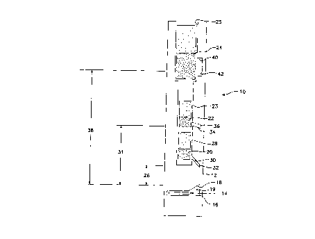
Turning to Figure 1, a three-detector form~tion density tool 10 is provided.
S The tool 10 features a housing 12 which may be composed of lil;.. ,il"" Ti~;.. il~
is a suitable material bec~llce it is strong and hard, yet has a relatively low density.
The low density of lili~ .ll is advantageous bec~ e it does not absorb as many
g~mm~ rays as other high-density materials. Alternatively, steel housings with low
density windows disposed imm~ tely in front of the detectors could also be used.If a li~ .. " housing is lltili7ed, low density windows are not n~cess~ry. However,
the embodiment shown in Figure 1 is ~csllme-l to include low density windows forclarity.
The g~mm~ ray source 14 may be cobalt-60 which produces 1.173 and 1.333
MeV p:~mm~ rays. Cesium-137 and accelerator sources may also be ~1tili7Pd. The
source 14 is disposed within a source cavity 16. A collimator 18 directs the g~mm~
rays ~uLwald in a general direction. Rec~llse the tool 10 is normally ope,al~d in a
decentralized position (see Figure 2~, the end of the collimator 18 or the source
window 19 will normally be abutting ~g~in~t the inside surface of the casing during
operation of the tool. The source cavity 16 may also be ~ulloullded with a
high-density shielding material such as t~lngc~en which helps prevent g~mm~ raysfrom procee~iing directly upward toward the detectors 20, 22, 24.
The first or near detector 20 is disposed from the source 14 by a
pre-deLe~ led ~li.ct~nre referred to as the first spacing 26. The first detector 20 is
accommodated in a compartment 28 that may be sul~oullded by a high-density
material, such as tungsten. A co~iim~tion channel 30 serves as a passageway
between the detector 20 and t_e housing 12. A low density window 32 may also be
provided. The combination of the collimation ch~nn~l 30 and window 32 and the
speci~lc angle of the collimation channel 30 enables g~mm~ rays that have been
-12-
SUBSTITUTE SHEET (RUEE 26)
CA 02203270 1997-04-21
W O 96112977 PCTrUS9S/10932
scattered by the casing to reach the first detector 20.
In co~ sL, the second r1~t~ctor 22 is disposed axially from the source 14 by
a second sp~çin~ 31. A second detector 22 is also cont~in~-l within a col~alL~ent
23 tllat may be ~u~ ded with a high-density material such as tlm~t~n which
def~es a collimation ch~nn~l 34 that extends between the outer surface of the
housing 12 and the second ~l~t~ctor 22. The second collimation channel 34
termin~tes at a second window 36. The second window 36 and second col1im~tion
çh~nn~l 34 permit ~,.""~ rays that are scattered primarily by the cement and thecasing to proceed up through the channel 34 to the second detector 22. Thel~rur~,
the second detector 22 ~refelelllially detects ~mm~ rays that are emitte-l from the
source 14 and then subsequently passed through the casing and cement before theyproceed up the channel 34 to the second detector 24.
The third ~letector 24 is disposed yet even farther than the second detector 22
at a third spacirlg 38 above the source 14. It will be noted that the third detector 24
may also be encased in a compartment 25 which is layered with a high-de~city
material which del~es a collimation channel 40. The collimation channel 40 and
window 42 that are subst~nti~lly wider than the second collimation channel 34 and
second window 36 as well as the first collim~tion channel 30 and first window 32.
This is bec~l-ce the third or far detector 26 is intended to detect ~mm~ rays being
scattered by the formation and to block those g~mm~ rays that travel a si~nific~nt
~ ct~n~e through the borehole. The ~width of the collimation channel 40 is n~cess~ry
to collect a reasûnable number of ~mm~ rays.
While the tool 10 of Figure 1 utilizes three detectors 20, 22, 24 that are
disposed above the source 14, it will be recognized that the detectors 20, 22, 24
could easily be disposed below the source 14 and still fall within the scope of the
present invention.
-13-
SUBSTITUTE SHEET (RULE ~6)
CA 02203270 1997-04-21
O96/12977 PCTAUS9S/10932
Turning to Figure 2, a schematic diagram of the tool 10 in use is provided.
The tool 10 is normally lowered to the bottom of the borehole 50 and pulled upward
by a wire line. The wire line also tr~n~mits signals from the tool so that the
formation density (pf), cement thickn~ss (tc) and casing thic~n~ss (tS) can be
calculated as the tool 10 is pulled upward towards the surface. The tool 10 could
also be ~lesign~(l to operate as the tool is being lowered downhill. The borehole 50
inr.h-~les casing 52 having a thickn~ss (tS); the casing 52 is set within the borehole
with cement 54 having a t~ickness (tc); and the formation 56 has a density (pf), all
of which can be me~llred by ~e tool 10.
The fIi~t~nres between the first letectQr 20, the second detector 22 and the
third detector 24 and the source 14 and geometries of the collimator 30, 34, 40 must
be design~?d so that the detector responses have dif~ferent se~ iviLies to the
formation, casing and cement. Tables 1 and 2 show the ratio of the cement
sensitivity to the casing sensitivity for various detector spacings. Table 1 deals with
cement thickn~sse~ ranging from 0.5 to 1.0 inches; Table 2 deals with cement
thickn~sses ranging from 1.0 to 1.5 inches. The ratio is presented for three dirr~lGll-
energy ranges and for the total count rates or intensities. Note that in Table 1(smaller cement thickn~sses) there is no .signifir~nt change in the ratio for spacings
greater than 16.25 inches, i.e. the 16.25 inch and 21.50 inch ratios are about the
same. The widest range in the ratio sensitivities (using the spacings and collimation
provided) is obtained from two extreme spacings and one in the middle. Thus, the4.5-inch, 8.~-inch and 16.2~-inch spacings should be close to the ~Li~ l spacings
required for cements less than 1-inch thick. On the other hand, Table 2 (larger
cement thickn~?sses) shows that the 21.50-inch ratio is significantly different than
the 16.25-inch ratio. Thus, longer detector spacings may be desired if the tool is
to log through cements thicker than l-inch. The detectors used are commercially
available sodium iodide crystal detectors with photmultiplier tubes.
- -14-
SUBSTITUTE SHEET (RULE 2B)
CA 02203270 1997-04-21
wo 96112977 Pcrlusssllos32
Figures 3, 4 and 5 illustrate the depen~ ce of count rate or i~ "~iLy on the
cement thiel~n~s~ for three dir~l~llL source-to-detector spacings, namely 4.5 inr.h~,
8.~ inches and 16.25 inches. Marble and fused silica are used to ~im~ te form~tion~
bec~--se the ~en~itiçs of the two ~ telials span the density range that will normally
S be encuulllelcd. As illustrated in Tables l and 2 above, the 4.5-inch spacing is most
se~.iLive to the casing relative to the cement while the 16.25-inch spacing is the least
s~L~iliv~ to the casing relative to the cement. In the anticipated ~le~i~n, the nearest
l~t~ctor will provide the ~liulaly i~lro~ ation about the casing, the middle let~ctor
will provide the ~lilllaly hlfol-llat:lon about the cement, and the far detector will
provide the primary infollllation about the formation. Thus, the arnount of cement
that the tool will be able to handle will be delellllillcd by the middle detector.
It will also be understood th;at the signals generated at each detector 20, 22,
24 could be divided up into various energy or "spectral" windows. For exarnple, the
g;~ rays re~rhinp the any one of the detectors could be cl~s~ eA by its energy
level and in~te~-l of one sign,al being generated per detector 20, 22, 24, anywhere
from two signals to several signals could be generated per detector depelldillg upon
the number of windows per detector. Energy windows are useful in analyzing
lithology, providing more accurate mlltlc~k~ correction and correcting tool variances
due to temperature changes. In ~e case of temperature stabilization, a small
calibration source that emits g~mm~ rays outside of the energy range or window of
the ~mm~ rays generated by the tool's main source is disposed adjacent to or
directly on the detector. If the signlal generated by the detector for the calibration
source g~mm~ rays flllct--~tes or drifts as the temperature of the tool ch~n~çs, then
2~ the tool can compensate change in signal due to temperature and the signals generated for the other energy windLows will be corrected as well.
Although only one specific configuration of the present invention has been
illustrated and described, it will at once be apparent to those skilled ln the art that
variations may be made within the spirit and scope of the invention. Accordingly,
SUBSTITUTE SHEET (RULE 26)
CA 02203270 1997-04-21
WO 96/12g77 PC~r/USg5/10932
it is intended that the scope of the invention be limit~ solely by the scope of the
hereafter appended claims and not by any specific wording in the foregoing
description.
-16-
SUBSTITUTE SHEET ~RULE 26)