Note: Descriptions are shown in the official language in which they were submitted.
CA 02203459 1997-04-23
FIFTH WHEEL BRACKET
FIELD OF THE INVENTION
The present invention relates to a bracket assembly for connecting a
tractor or truck with a trailer. More particularly, the present invention is
directed to
a new and improved bracket assembly designed to secure the top plate or fifth
wheel to a truck frame and permit connection of the trailer to the truck.
BACKGROUND OF THE INVENTION
In the art to which this invention applies, it has generally been the
practice to provide an apparatus for attaching a trailer of a semi trailer-
type rig to a
truck to insure a pivotable, easily releasable yet sturdy and strong
connection.
Traditionally, the connection between the truck and the trailer has been made
by
pivotally securing a downwardly depending king pin carried on the front of a
trailer
to a lockable latching mechanism commonly called a "fifth wheel." The fifth
wheel
is secured to the rearward frame or chassis of the truck. More particularly, a
base
plate is secured to the rearward chassis or frame of the truck and generally
disposed in an orientation parallel to the road. A pair of support members are
provided and positioned adjacent to the edges of the base plate and secured
thereto. Each support member generally includes a means for pivotally securing
a
top plate thereto such as an opening for receiving attachment pins. A top
plate
with an inwardly and centrally positioned throat for retaining and locking the
downwardly depending king pin of a trailer is positioned to be carried by the
support members. The top plate generally includes a latching mechanism for
CA 02203459 1997-04-23
releasably retaining and locking the king pin in the throat. The top plate is
generally pivotably connected to the support bracket by inserting a pin
through a
portion of the side of the top plate and the support member. The pins are
usually
inserted along an axis transversely of the truck and road. This configuration
permits the top plate to be rotatably secured to the truck.
The top plate of some prior art fifth wheels may include a skirt that
depends downwardly from its outer edge. When the top plate is placed over the
support brackets, a portion of the skirt is positioned parallel and outwardly
adjacent
to each of the support hatchets. The top plate may also include a downwardly
depending flange parallel to and spaced inwardly from a portion of the
depending
skirt of the top plate so as to form a generally U-shaped inverted channel
that fits
over the support brackets. The downwardly depending flange and the downwardly
depending skirt also have openings therethrough that align with and are
coaxial
with openings in the support members. A pin is inserted through the depending
skirt portion into each of the support brackets and the downwardly depending
flange connecting the top plate to the support brackets. The top plate now
secured to the truck is then capable of receiving the king pin from the
trailer and
securing it to the truck.
In these prior art arrangements, significant loads are delivered to the
bracket and pin assembly as a result of the tendency of the top plate to move
upwardly away from the support brackets due, for example, to bouncing and side
to side movement of the trailer. In addition, overturning loads are produced
when
the truck is turned, even at low speeds. With overturning, there is a tendency
for
the top plate to lift up at one of the support bracket locations. This
tendency for
CA 02203459 1997-04-23
the top plate to lift up and away from the support brackets produces shearing
forces on the pins. Shearing forces may cause deformation of the pin
considerably weakening the connection between the truck and trailer, and may
also
damage the fifth wheel ultimately resulting in down time of the truck for
repairs.
In view of the above, there remains a need for a bracket assembly that
is inexpensive, strong, and capable of withstanding the loads created by
movement
of the top plate relative to the bracket assembly. In addition, there is a
need for a
bracket assembly that assists in distributing the shearing forces incumbent in
connecting a truck to a trailer.
SUMMARY OF THE INVENTION
The purpose and advantages of the invention will be set forth in and
apparent from the description and drawings that follow, as well as will be
learned
by practice of the invention. Additional advantages of the invention will be
realized
and attained by the elements of the apparatus particularly pointed out in the
appended claims.
To achieve these and other advantages and in accordance with the
purpose of the invention, as embodied and broadly described herein, the
bracket of
the present invention includes a bracket assembly for connecting a fifth wheel
to a
truck. The assembly includes a base adapted to be secured on the rearward end
of
a truck. A pair of spaced apart retainer assemblies are connected to the base
and
disposed adjacent opposite edges of the base. The retainer assemblies include
spaced apart support plates disposed substantially perpendicular to the base.
One
of the support plates includes a pin securing opening. The bracket assembly is
also
- 3 -
CA 02203459 1997-04-23
provided with a cylindrical tube portion coaxial with the pin securing opening
and
carried on the support plates. A radially reinforced bushing is seated in the
cylindrical tube portion. The reinforced bushing includes a bore therethrough
coaxial with the pin securing opening.
In an additional embodiment of the present invention, a top plate is
provided adapted to receive and secure the king pin of a trailer. The top
plate is
disposed over the pair of retainer assemblies and includes a peripheral
downwardly
depending skirt and a saddle formed inwardly from said skirt portion. The
saddle of
the skirt portion is adapted to engage the cylindrical tube portion of the
retainer
assemblies. A portion of opposite ends of the skirt are disposed parallel to
and
outwardly from the support plates and include an aperture therethrough. A pair
of
bracket pins are provided each extending through the aperture in the skirt,
the
opening in the support plate and through the bore of the reinforced bushing
respectively. In addition, a pair of locking pins are provided for preventing
the
removal of the pair of bracket pins.
It is to be understood that both the foregoing general description and
the following detailed description are exemplary and provided for purposes of
explanation only, and are not restrictive of the invention, as claimed.
BRIEF DESCRIPTION OF THE DRAWINGS
The accompanying drawings, which are incorporated and constitute a
part of this specification, illustrate the preferred embodiment of the
invention, and
together with the description, serve to explain the principles of the
invention.
Fig. 1 is an isometric view of the present invention.
- 4 -
CA 02203459 1997-04-23
Fig. 2 is an isometric view of an alternative embodiment of the present
invention with the top plate of the present invention shown in phantom lines.
removed.
Fig. 3 is an isometric view of the present invention with the top plate
Fig. 4 is a cross-sectional view of the bracket assembly of the present
invention of Fig. 1 taken along lines 4-4.
Fig. 5 is an isometric view of the reinforced bushing used in the
bracket assembly of the present invention.
Fig. 6a-c is a side, bottom and top view of the bracket pin of the
present invention.
invention.
Fig. 7a-b is a side and top view of the retainer pin of the present
Fig. 8 is a plan view of the underside of the top plate of Fig. 1 of the
present invention.
DETAILED DESCRIPTION OF THE PREFERRED EMBODIMENT
Reference will now be made in detail to the present preferred
embodiment of the bracket of the present invention for attaching a trailer to
the
tractor examples of which are illustrated in accompanying drawings. Wherever
possible, the same reference characters will be used throughout the drawings
to
refer to the same or like parts.
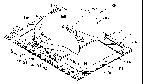
An exemplary embodiment of the preferred bracket assembly of the
present invention is shown in Fig. 1 and designated generally by reference
character 100. Fig. 1 shows the top plate 102, commonly referred to as a fifth
wheel, the lower bracket assembly 104, and the base 106.
Referring now to Fig. 3, the base 106 includes a generally rectangular
base plate 108. The base plate 108 includes openings 110 for receiving a bolt
for
- 5 -
CA 02203459 2005-02-07
L_.
securing the base plate to the main ch8ssis ar frame of a truck tnat showni.
Turning now to Fig. 1, the base plate 108 may be carried on a frame 712 having
elongated spaced apart parallel panels 194 and spaced apart cross panels 116
connected across the ends of the elongated panels 114 forming a generally box-
shaped frame 712. Rails 1 i 8 are disposed along the outer edge of the
elongated
parallel panels 114.. The raNs 118 are secured preferably be screws or bolts
through the frame 112 to the truck frame. The rails 118 form channels 120
which
receive the lateral edges ofbase plate 108 and guide the base plate 108 to
selected positions along the truck frame. Disposed on the rearward end of the
base plate 148 are generally upstanding rocker limit blocks 7 22 designed to
limit
the rocking motion of the top plate 102 when seoured to the retainer assembly
104.
Alternatively, as shown In Fig. 2, the base plate 108 may be secured
to a pair of elongated angle irons 124 having a series of openings 126
disposed
along the horizontally disposed flange portions 128. 'fhe angle irons 124 are
attached to the main chassis or frame of the truck preferably with nuts and
bolts.
The base plate 108 may be secured to selected positions along the truck frame
by
_ moving th~ base plate to a desired position on the angle iron e'nd securing
the bds~e
plate 108 to the angle iron through hales 126.
deferring again to Fig. 3, the lower bracket assembly 104 is carried an
the base plate 108 and generally includes a pair of spaced apart upright
retainer
assemblies 130 which are positioned toward the lateral edges of the base plate
108. Each retainer assembly 130 includes a pair of upstanding support plates
132A and 1328 spaced apart from each other and a generally triangular brace
134
_ a ..
CA 02203459 1997-04-23
connected to the support plates 132 forming a generally hollow cylindrical
tube
136 supported by the two upright brackets. Communicating with the generally
hollow cylindrical tube 136 of each retainer assembly is an opening 138 of a
predetermined diameter formed through the support plate 132A closest to the
lateral edge of the base plate 108. The diameter of the opening 138 through
the
support plate 132A is generally sized to accommodate a bracket pin 140 of the
type illustrated in Fig. 6 and permit limited movement of the pin in the
opening. To
permit limited vertical movement of a bracket pin 140, the opening 138 may be
configured as a vertically oriented oval.
Spaced inwardly from the opening 138, the tube 136 of considerably
larger diameter extends inwardly and terminates at an inwardly formed rim 142.
The opening 138 and the central axis of tube 136 are coaxial. The retainer
assemblies 130 may be integrally cast or welded together. It is preferred that
the
retainer assemblies 130 be constructed of fabricated or cast steel. The
retainer
assembly 130 is secured to the lateral edges of the base plate, preferably by
welding.
The final element of the retainer assembly includes a reinforced rubber
bushing 144, preferably formed integrally with a steel washer of substantially
identical outside diameter, as illustrated in Fig. 5. The diameter of the bore
through
the rubber bushing is generally sized to receive a bracket pin 140 preferably
of the
type illustrated in Fig. 6. The pin should preferably fit snugly within the
bore
through the bushing 144. The opening in the steel washer that reinforces the
rubber bushing should preferably be slightly larger in diameter than the bore
through the bushing. This arrangement permits the rubber bushing to dampen
CA 02203459 1997-04-23
vibrations transmitted through the pin 140 and also permit the steel washer to
distribute the shearing force. The rubber bushing 144 is sized and shaped to
fit
snugly into the hollow cylindrical tube 136 of the retainer assembly 130. The
rubber bushing 144 is sized preferably so that it is maintained in the tube
136 by
an interference fit. The rubber bushing 144 is comprised preferably of a
relatively
hard rubber or other elastomeric. Alternatively, as shown in Figs. 3 and 4,
the
rubber bushing may be reinforced with a steel washer 146, of the substantially
same outer diameter that is positioned adjacent the bushing 144 in the tube
130.
As illustrated in Fig. 4, the steel washer adjacent the bushing provides
additional
support and strength to the assembly 100 by distributing the shearing force to
which the bracket pin 140 is subjected. The effect is to change the forces
acting
on the pin from single shear to double shear. In addition, the reinforced
bushing
144 may act to reduce or dampen some of the vibration created in the bracket
assembly during movement of the truck and trailer.
The top plate 102, as illustrated in Fig. 1, also referred to as the fifth
wheel, includes a large flat plate 148 with a gradually narrowing throat 150
formed
in the center. A skirt 152 depends downwardly from the outer edges of the top
flat plate 150. The skirt 152 is preferably integrally formed with the flat
plate. The
center of the underside of the flat plate 150 includes a latching mechanism
151
(shown generally in Fig. 8) for securing the king pin of a trailer to the top
plate
102. A variety of configurations for the latching mechanism are available and
well
known in the art. Latching mechanisms of this type generally include a jaw
which
secures the king pin in the throat of the top plate and a wedge for locking
the jaw
in place.
_ g _
CA 02203459 1997-04-23
Laterally adjacent the latching mechanism, the underside of the flat
plate includes a saddle area 154 formed along opposite sides of the top plate
102
as illustrated in Fig. 8. The saddle 154 is formed by a portion of the
depending
skirt 152, the flat plate 148, and a flange 156 downwardly depending from the
underside of the flat plate 148 and inwardly spaced from the skirt portion
152.
The saddle 154 may include a generally arcuate saddle bearing surface 158 that
is
sized to accommodate and engage the hollow cylindrical tube 136 of the
retainer
assemblies 130. The depending skirt portion 152 includes an opening 160
coaxial
with a similarly sized opening 162 through the inwardly spaced depending
flange
156. The similarly sized openings 160, 162, are sized to receive the bracket
pin
140 when the top plate is secured to the lower bracket assembly.
As shown in Fig. 6, an elongated cylindrical bracket pin 140 is
provided for securing the top plate to the retainer assemblies. The bracket
pin 140
is sized to extend from the opening 160 in the depending skirt portion through
the
opening 162 in the inwardly spaced depending flange portion 156. The bracket
pin
140 includes a rectangular stop 164 connected to the rearward end of the pin
140.
The stop 164 is preferably welded to the rearward end of the pin and is longer
than
the diameter of the opening 160 in the depending skirt portion.
A retainer pin assembly 166 illustrated in Figs. 1 and 4 includes a
generally hollow cylindrical tube 168 disposed in a vertical orientation and
which is
shown in Fig. 1 welded to the outer surface of the depending skirt portion 152
above the opening 160 through the skirt portion. A retainer pin 170 shown in
detail in Fig. 7 is provided to be inserted through the vertically disposed
cylindrical
tube 168 and abut the end surface of the stop 164. The retainer pin 170
includes
_ g _
CA 02203459 1997-04-23
a flat partially circular head 172, larger in diameter than the pin 170 that
is adapted
to engage the top edge of cylindrical tube 168 to prevent the pin 170 from
dropping through the tube 168 and maintaining the bracket pin 140 in place.
The bracket assembly 100 of the present invention provides increased
overturning strength of the assembly and permits a more even distribution of
the
load during overturning and stresses on the bracket assembly. In a typical
installation, the frame 112 is attached to the main chassis or frame of the
truck by
bolting the frame to the chassis. The frame 112 may be additionally secured to
the
truck by providing bolts through the rails 118. The base plate 108, which has
the
retainer assemblies 130 secured thereto, is positioned in the channels 120
formed
by rails 118 and slid to an appropriate position on the truck frame and
secured
thereto as by bolts extending through openings 110. The position of the base
plate 108 and lower bracket assembly 104 on the truck frame is determined in a
manner well known in the art based on a variety of factors including the type
of
trailer, the type of truck, and the load to be attached to the truck. Once the
base
plate 108 is secured to the truck frame at its desired location, a reinforced
bushing
144 is inserted into each of the hollow cylindrical tubes 136 so that the
front face
of the rubber bushing butts up against the support plate 132A. The bushing 144
should fit snugly in the tube. The rubber bushing 144 is generally sized so
that it
will remain seated in the hollow cylindrical tube 136 and form an interference
fit
within the hollow tube 136. The rubber bushing may be integrally reinforced or
reinforced with a steel washer of the identical diameter positioned adjacent
the
bushing in the tube 136 as described above.
- 10 -
CA 02203459 1997-04-23
The top plate 102 or fifth wheel is then placed over the lower bracket
assembly 104 and the retainer assemblies 130 so that a portion of the
depending
skirt 152 is positioned generally parallel to and outwardly adjacent from the
support plate 132A as illustrated in Figs. 1, 2, and 4. In addition, the
downwardly
depending flange portion 156 of the flat plate 148 is positioned generally
parallel to
and inwardly adjacent the support plate 1328 and the rim 142 of the tube 136.
The top surface of the hollow cylindrical tube 136 then fits within the saddle
154
of the top plate 102 providing contact between the saddle bearing surface 158
of
the top plate and the tube 136 of the retainer assembly 130. The openings 160,
162 through the skirt portion 152 and the downwardly depending flange portion
156 of the top plate 102 should be coaxially aligned with opening 138 through
the
support plate 132A and the longitudinal axis of the hollow cylindrical tube
136.
Bracket pin 140 is then inserted through the opening 160 in the
depending skirt portion, the opening 138 in the first upright plate, the
bushing 144,
the opening formed by the tube support 136, and the opening 162 in the
downwardly depending flange portion 156 of the top plate 102. When the bushing
is reinforced by an adjacently positioned steel washer, the pin 140 would also
extend through the steel washer as illustrated in Fig. 4. The bracket pin 140
is
inserted until the stop 164, secured to the rearward end of the pin 140,
engages
the skirt portion 152 of the top plate. A retainer pin 170 is then inserted
through
the vertically disposed hollow tube 168 until it engages the stop 164
connected to
the pin 140 to prevent the bracket pin 140 from backing out of the bracket
assembly 100. The top plate 102 is thus securely attached to the lower bracket
assembly 104 and permitted to rock or rotate about the axis defined by the
bracket
- 11 -
CA 02203459 1997-04-23
pin 140. It should be understood that two bracket pins 140 are utilized in
securing
the top plate 102 to the lower bracket assembly 104 -- one for each retainer
assembly 130.
One of the advantages apparent from the present invention is that the
use of the reinforced rubber bushing assists in distributing the shearing
forces on
the bracket pin 140 when a load is applied to the bracket assembly. This
arrangement thus provides greater overturning strength of the bracket
assembly.
It is also intended that the reinforced bushing 144 of the present
invention may be added to existing bracket assemblies to provide the benefit
of
greater overturning strengths and the re-distribution of shearing forces.
During movement of the tractor-trailer assembly, there is a tendency
for the top plate, which connect the tractor and trailer, to lift upwardly
away from
the lower bracket assembly. When this occurs a force is applied normally to
the
longitudinal axis of the pin 140 at points where the radial movement of the
pin 140
is restricted, such as by the annular surface of openings 138 of support plate
132A. By including a steel washer adjacent the bushing or an integrally
reinforced
bushing, a portion of the load or shearing force is acting on the pin 140 at
one
point effectively distributed to another portion of the pin thereby reducing
the
concentration of the shearing force at any one portion along the pin 140.
Consequently, the overall strength of the bracket is increased. In addition,
the
rubber bushing assists in dampening the vibrations that occur between the top
plate and the lower bracket assembly.
The present invention incorporating the reinforced rubber bushing also
more evenly distributes the load during overturning such as when the trailer
pivots
- 12 -
CA 02203459 1997-04-23
relative to the truck. During this type of motion, there is a tendency for the
top
plate 102 to tilt and raise up at one or the other of the retainer assemblies
130.
The present invention assists in distributing the load.
In view of the description above, it is evident that the present
invention provides a new and unique bracket for attaching a top plate of a
fifth
wheel to the tractor or truck. Although reference has been made to the use of
the
present invention, it will also be apparent to those skilled in the art that
various
modifications and variations can be made in the design and construction of the
bracket assembly without departing from the scope or spirit of the invention.
Other embodiments of the invention will be apparent to those skilled in
the art from consideration of the specification and practice of the invention
disclosed herein. It is intended that specification and examples be considered
as
exemplary only, with the true scope and spirit of the invention being
indicated by
the following claims.
- 13 -