Note: Descriptions are shown in the official language in which they were submitted.
CA 02203523 1999-O1-28
A
6/13916 PCT/CI395/02533
'~
Communication Method and Apparatus with Transmission of a Second Signal
during Absence of a First One
Tsc::::ica; ~ ; ~ia
The _ =esent ;nver_ticn relates ~o a comma..~.ication
method a:.d a_~naratus, and partic::iariy bur_ rot ~xc?usivelv
S to a method and apparatus ::or orovid=rig da,_a cornmu:r;cation
over a radio Frequency channel i:: ad~'itio;i to void, image
or other data communication.
9ackaround Art
In a known radio frequency communicati.cn system, for
example the INMARSI1T-A (TM) Satel_te CommunicaCi_o:i System,
as desc=ibed for example in "Satellite Communications:
Pri:~ciDles and ADplicaticns", Calcurt and ieCleV, 1st
edition ?994, users are connected to a public service
tel ephone Fretwork (PSTN) through a stx,_e1 1 ite 1 ink to
provide voice, Facsimile and ci_cui~. switched data
communication ser~-ices. Attempts have beer made to add a
packet switched data service, in wiric:~ users snare a single
channel, to rife existing services available through
INM~..RSAT-A. However, this requires the allocation of
additional traf~ic channels, which adds to the cost of the
system.
The document GB-A-2 232 562 describes a digital mobile
~elephone svscern with a data communications ~u:lccion. If
a data communication is asymmetric, time slots which are
not needed for communication in one direction are
reassigned for data transmission in the opposite direction.
The time slots may be reassigned to a different data
terminal. However, such a system reQUires reallocation of
part of a physical channel assigned for communication in
one direction so as to change. the direction and/or data
terminal to which. that part is assigned.
Disclosure of Invention
According to one aspect of the present invention there
is provided a method of radio-frequency communication to
separate first and second mobile terminals, the method
comprising, storing data for transmission to said second
mobile terminal, setting up a communication with said first
CA 02203523 1999-O1-28
' 96/13916 F(.'T/GB95/02533
' 2
mobile terminal via a radio-frequency channel, detecting an
absence of information in said communication, and
transmitting one or more data packets derived from said data
and addressed to said second mobile terminal in said radio-
frequency channel during said absence.
Durinc voice communication, a proportion. o' ~:~e time
during whic:o a c:~annel is kept open is unused, for example
when a user is 'istening without ~:alking, so that the
user's transmi~ channel carries only noise. Likewise, in
a facsimile communication, a t~rrninal_ which receives
facsimile data only transmits duri ng the handshaking phases
of the communication; at other times it.s transm~.t channel
is unused.
Tn embod_ments of the invAntion the available
bandwidth oL the communication channel is used with Greater
efficiency, and a data communication service may be
provided concurrently with another service.
PreTerably, the principal signal cornDrises a voice or
facsimile signal.
Where the pri~cipal signal i s a voice s i gnal , t.ne data
signal ~s transmitted during periods oz silence. Ths first
earth station may transmit a silence code which is decoded
by the second earth station to rep-oduce silence~or low-
level noise during a voice communication. Preferably, the
third earth station interprets the silence code as a signal
to receive data.
Alternatively, the first earth station may transmit a.
signal which is reproduced by 4he second earth station as
acceptable (e.g. low-level) noise or silence but which is
decoded by the third earth station as data, during the
periods of silence.
Where the principal signal is a facsimile signal, the
first station may detect whether the second earth station
is transmitting facsimile data and therefore does not need
to receive any Tacsimile data. The first station transmits
CA 02203523 1999-O1-28
x'/13916 PCTIGB95/02533
3
t:le s;gna 1 _.._iu,_:i~c ;.he ca'a sicnai _~ suc~.
a wa'.~ ~r~at y_
QOes ::Ct aCC_'!aW i.ne faCSlmlle .'_°''m=nal at t!:~ seCOnC
e~rC~1 StatlC: , 'Jilt aCt~JaC~'S i.: a t::'_=d r?c-'1''th sCCt=Orl t0
receive data.
cy the move measures, the seconc a:~d third stations
tray receive data concurrently, witi-= the seconc earth
5t~tie:~ only decoding the principal signal and the third
earth staticn only decoding ~h~ data, but without
inter.=_rence between. the signals. This aspect of the
?0 presen~ inversion extends in particular to the first
sta~icn, the ~hi~d station, apparatus within the first or
third station which: i;~plement the essential features of the
presen~ invention and any method performed by such
apbara~us.
According to another aspect of the present invention,
there is provided an apparatus for radio-frequency
communication to separate first and second mobile terminals,
comprising, storing means for storing data for transmission
to said second mobile terminals, set-up means for setting up
a communication with said first mobile terminal via a radio-
frequency channel, detecting means for detecting an absence
of information in said communication, and transmitting means
for transmitting one or more data packets derived from said
data and addressed to said second mobile terminal in said
radio-frequency channel during said absence.
brief Description~~of Drawings
Specific embodiments of the present invention will now
be described with reference to the accomti_anying drawings in
which:-
3~ Figure 1 is a diagram showing the logical connection
between earth stations in embodiments of the _present
invention;
Figure 2 is a functional block diagram of a land earth
station according to a first embodiment;
°igure 3 is a block diagram of a voice codec according
~
~ CA 02203523 1997-04-23
WO 96/13916 PCTlGB95102533
a
to the _-rs= =-ibodiment;
F ~.g;lre G _S a _OWChar t Of ... a Cpera~r.Crl C~ t.!'~e 1 and
earth staticr;
_ =gore ~ i-s a _unct~.ena 1 block diagram of a second
mobi l a ear ~'.~. s=ation;
Figure 5 .s a flowchart of ~~e operation of t a second
mobile eart~ station;
Figure 7 shows tie format of a packet transmitted by
the land eart~. station according to the first embodiment;
F figure a is a Lunctional b 1 ock diagram of a packet
data interface unit according to a second embodiment;
Figure 9 is a block diagram of the packet data
i
F
interface unit including a PCM cosec;
Figure 1C is a schematic diagram of an AFC coder and
decoder;
_igure 1- is a functional block diagram o. a land
earth station according to a third embodiment;
Figure 12 is a flowchart of the operation of the land
earth station according to tile third embodiment;
i
Figure '_3 is a diagram of the packet format of a
signal transmitted by the land earth station according to i
tine third embodiment cf the present invention.
Modes for Carrvinc Out the Tnvention
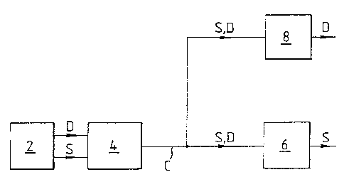
Ffigure 1 shows schematically a communication system in
which a network station, such as a land earth station (LES)
is connected to a public service telephone network (PSTN)
2. The LES ~ is arranged to provide a satellite link
between a r_umber of users connected to the PSTN 2 and a
number of user terminals, such as mobile earth stations
(MES) which are able to receive and decode signals S
transmitted by the LES 4 via a satellite, and to encode and
transmit signals to the LES a via the satellite. Figure 1
shows a first MES 6 and a second MES 8, both in
communication with the LES Q by means of a single channel
C.
The nature of the channel C depends on the addressing
techniaue used. For example, in a single channel per
CA 02203523 1997-04-23
WO 96/13916 PCT/GB95/02533
.
Car=ie_ ;SCPC) system, ~ c annel correspc :ds to a single
Car r ? er =r eQllenCy ;n a na1 L Cu-p! °_Y SyS; e;~ ~= ,... ,_,a
it ~,'
Car r' er =reauenci es ~.:1 d ful 1 dupleX SVSL°_T:'~. =n a
'~'T,JjV~
System, a Chdnnel C.CrreSpOndS t'J d preQeter;.';=neQ t_;,ie Slot
in a repeating ti~,e name OL d tranSmiSSiGn dt a DartlCLlar
requecy or set cf freauencies . ' n G ~SM.~ system, a
channe~ correspcnds ~o a transmission e::coded with a
predetermined code. The present invention does not depend
on the addressincr system used.
The LES e_ also receives data D, addressed to the
second MES 8, _;om the PSTN 2. The data D ~.s stored at the
LES ~ until _.. can be transmitted. The data ~ may
alternatively ~dve been entered directly at the LES a or
orevio~sly received from an MES.
_-. order .-.o estab l i sh a communi catioTs link with the
_irst MES 6, the LES ~ transmits a predetermined calling
code =dentifyirg the first MES 6 on an _ES signalling
channel. The calling code includes a service-t~,'pe code
which identif_es whether a voice, facsimile or data
2o t.rarsmission is to Lollow. The ~irst MF,S 6 acknowledges
the calling code on an MES signalling channel iL it is
ready to communicate. A communications link is then
allocated by do independent network control station.
__ the LES ~ receives data D addressed to the second
MES 8, it transmits a predetermined data addressing code on
th°_ LES sigr_alling channel and the second MES 8
acknowledges the data addressing code i= it is ready to
receive the data. The data addressing code. includes
information on the communications link which will be. used
for data transmission. ,
A first embodiment of the present invention will be
described with reference to Figures 1 to 7. In this
embodiment, a racket switched data service is provided in
addit'_on to a voice communication service such as the
INM.~1RSAT-M (TM) system as also described ir_ the Calcutt and
Tetley reference above.
First, a call is set up between the LES 4 and the
~
, CA 02203523 1997-04-23
WO 96113916 PCT/GB95l02533
0
.- =irs~ MES 5:step .02). The ~a=- may be ini~=ated by
e~.th~?' the lrJS 4 C'_" the _--'St Mr.S .. .
~ur~.nQ th~ Ccl~=, a Vo~.Ce slgaal ~ is ~e.~.e.~rve~' ~rom the
PST c by a cosec ;0 of the TES 4. ~etai_s of the cosec
used in the ;NM_PRSAT-M ~:TM) system are descr;bed for
example in the Calcutt and Tetley =eference. This cosec 10
uses an Improved Multi-Band Excitation (IMBE) algorithm,
shown schematically in Figure ~. The voice signal V is
analysed by a pitch estimation stage 46 which esti,;:ates the
fundamental _=equency i~_ of the voice signal V. A
voiced/unvoiced determination stage ~8 evalur..tes the
voici ncr measure oT each of a n:~mber of nor.-over 1 apping
frequency bands of the voice spec~rum and genera~es a set
of decisions ~a as to whether the voice signal v =s voiced
or unvoiced .__ eac~ band. A snec~ra~ amplitude estimation
stage 0 _determines the spectral envelope M- of each
frequency band according to whether the band is determined
to be voiced c; unvoi ced. The values i~~, VY, M, are encoded
for each 20 ms frame of speech to ~orm a series c~ vectors
Uo to U; . Error correction informati on is added prior to
radio frequency modulation and transmission.
Tiowever, if the cosec 10 does not detect any vocal
characteristics i_~_ the voice signal V, it sets the first
six bits of vector U~ to 110010 (decimal 50) to form a
silence code.
In the _irst MES 6, another cosec 52 decodes the
values oz ~;o, V,~ and M, and synthesises unvoiced and voiced
speech signals at unvoiced speech.synthesizer 54 and voiced
speech synthesizer 56 respectively. The outputs of the
synthesizers 54 and 56 are added to~produce a synthesised
speed signal VS. Alternatively, if the cosec 52 receives
the silence code, it generates low level "comfort" noise
and does not decode any other information.
The LES 4 includes a packet data interface unit 12
which normally receives encoded data from the cosec 10 and
sends the encoded data (step 106) to a radio frequency (RF)
modulator 1a for transmission ;oy an antenna 16 to a
CA 02203523 1997-04-23
WO 96/13916 PCT/GB95/02533
7
sazel __..~ ~:nct show ~ . 'T'he ==rst MyS 5 i_~.c'_~.:des a
demOdi:_at~~ _~= G°_'.T?OG:~lat__"~ tr:2 S~C;::a! receitred _=Om the
LES 4.
::cwever , wnen the packet data _..teryace unit ' 2
receives a siler_ce code _rom tine codes 10 (step ~0~) , it
outputs the data D (step 108) in a data packet 20 as shown
in !=ic-,~re ; . The data packet 20 incl udes a si 1 ence code
SC, an identity code ~D w~zich identifies the second MES 8
to whica the data ~s to be sent, and the data D itself.
The data packet 20 i= transmitted via the satellite and is
received by both the ~~.rst MF.S 6 and by the second MES 8.
The process repeats Lntil the call is ended (step 110).
T~°_ =i rst i~:ES 5 is set un to receive a voice
commur_ication and therefore responds to the si 1 once code SC
by ig~':Cr~~l.~. t~e reSt Ct the Qata packet 20. L'JW ~ eVel
white :o~se (or c~her "comfort noise") is generated by the
codes 52 at the =first MES 5 in response ~.o tre silence code
SC to -eassure the user that the communications channel is
still open.
___ the secor_d MES 8 , as shown in Figure S and in the
flowci-:ar t ef _ figure 6 , the data packet 20 i s received by ar_
antenr._a 21, rF demodulated by an R: demodulator 23 and
decoded by a decoder 22 which detects whether data is being
sent !step 112), by detecting the presence of the silence
code SC. The decoder 22 extracts the identifying code ID
and compares i t with a code stored in a comparatcr 25 (step
114). If the codes match, the comparator 25 closes a data
switch 26 and the decoder 22 outputs the data D (step 116).
The data D is output to a local network or storage device,
such as an e-mail system. The.process continues until the
last block of data D is received (step 118).
second embodimer_t will now be descr i bed with
reference to Figure a to 6 and 8 to 10. This embodiment is
applicable to a system which uses a codes 24 that does not
provide silence detection, such as for example the
INMARSAT-3 (TM) system.
The LAS ~ i n thi s embodiment includes a packet data
CA 02203523 1997-04-23
WO 96/13916 PCTIGB95/02533
8
interlace unit =2 hav_nc a voice activi:.y detector ('J'ADi 28
WhlCn Q~teC.'_S W_~.ettl°_r .'_!?e Ot1t1:7Llt ~_ t_'!e COCL°_C
~4 re'J?"esent5
Only baC~CQ=OL1I:~ n OlSe tSteD 1 ~4) . A.:'1 eXample Gf ..__.S type
Of deteCtO'_", ~ Si:? to.~'~J'._°_ ~rJr an ~:= ~ CJdeC used i:
~:?e GSM
system ) is descr ibed i_~_ US Paten t ~'c . 5 , 276 , 765 . ~_ he VAD
28 act_vates a switch 30 with switches the output of the
packet data i nterfaCe unit i2 yrOL'.l the OutDUt OL '~'?°_ COdeC
24 (Step 106) to the signal :~ (step 108) if no vcice is
detected.
_=~ this eT,nodiment the data D must be encoded so as to
be acceptable nor acoustic reproduction by the first mobile
earth station o, since the i?rst MES 6 is not arranged to
recognise a silence code and so cannot ignore a received
siQ:~al as in the first embodiment. T'~e data D is thereyore
encodea ~'JV a Qata onCO'.1' er ~ 2 t0 -"apreSent lOw 1 ''cVe_ noise
to the cosec o. the =first MES 6.
The technaue used by the data encoder 32 dep'nds on
the type of cosec used by the first MES 6. In or_e ehample,
shown =n Figure 9, the cosec 2~ uses 8-bit pulse code
modulation (PCM). The VAD 28 receives the output of the
cosec 2~ and analyses whether a voice is present. ~he data
encoder 32 ccm~rises a First Functional section 32a which
encodes the data D into the four least significant bits
(LSB) (D~ ~~ ,) in resDOnse to an output of the VAD 28
indicating that no voice is present and a second functional
section 32b which outputs zeros as the four most
significant bits (MSB) in response to the output of the VAD
28 , so that the decoded output signal sounds like low-level
noise. The first and second Functional sections 32a, 32b
allow the output of the cosec ~4 to pass when the VAD 28
outputs a signal indicating that a voice is present.
Alternatively the data D may be spread-spectrum encoded by
the functional section 32a so as to sound like low-level
noise. Tn another alternative, shown in Figure i0, the
cosec 2~ uses adaptive predictive coding (APC) as in the
INMARSAT-3 svstem. T_n an APC coder, a predictor 60
generates an estimation cf the _~.put speech signal V in
CA 02203523 1997-04-23
WO 96113916 PCT/GB95102533
, 9
terms C- a S°_L :W SnCr' tern '_"e_'.~cV=-OD CCe=t_C? °___~_'S.
IOnC
term toe==icien is anti Gn optimum _.m.s. scalinc value. ~he
Outptlt Ci Lhe D~eClCt~r 60 ? S S1-WLraCt°_d .rOT ~ he aCtl~a1
VOlCe SiQna~ by a SuDtraCter 62 anQ t!'!e reS?Qua! Signal iS
Output tC a q'.:an tiler 64 . The COeff~Ciem.S and the
quant'_zed residua! Signal are tra:~SmltteCl. ~:~ an APC
decoder 53, the quantized residual signal -s sent to an
inverse Quantizer 56 while the toe=ficients are sent to
another predictor 70 so as to reconstruct the speech signal
V5. Sel ected toe=ficients such as tine reflec~ion
coeff_c?ents may be used to carry the data, while the
remaining coefzicients are set to zero so teat no sound is
generated at the codes 53 of the first MES 6.
Referring to Figures 5 and 6, .n this embodiment tine
decoder 22 of the second MES 8 recocrnises (step 112) an
encoded sequence in the data encoded by the data encoder 32
and compares (step 11~) the encodes sequence with a code
stored in a comDarator 25. If the encoded seQUence matches
the code, the comparator closes the data switch 26 and data
D is output (step 116) from the second MES 8 as in the
first embodiment.
A third embodiment will now be described with
reference to Figures 11 to 13. In this case, the LES 4 is
connected through the PSTN 2 to a receiving facsimile
terminal which sends facsimile protocol signal and the
first MES 6 is connected to a transmitting facsimile
terminal which sends both protocol signal and facsimile
data. The protocol signals may for example comply with
CCITT (now ITU-T) recommendations T.30 and T.4. The
protocol signals establish the communication mode of the
terminals during a pre-message procedure, correct errors
and indicate multiple pages during message transmission and
signal and acknowledge the end of a transmissior_ during a
post-message procedure. Both facsimile terminals operate
in half-duplex mode, so that they cannot receive data
whils~ they are transmitting. However, a full duplex link
is set up between. the LES ~ and the First MES 6, since the
CA 02203523 1997-04-23
' a , , ~ , " r "
;, " ,~ ,., ~ -, - ~ ~
, , -, - , ~ "-
y ~ '! . ~ 1 7 . ',, , .
. O 7 , , ~ l 1 ..
1 n ~" "~ "~ ,~l '
same channel type is used for voice and facsimile
communication.
The LES 4 includes a facsimile interface unit (FIU) 36
which converts the facsimile protocol signals F from the
5 PSTN 2 to data suitable for transmission by the radio
frequency interface unit 14, and converts data received
from the radio frequency interface unit 14 to facsimile
signals suitable for sending through the PSTN 2. Such a
facsimile interface unit is described for example in
10 British Patent Publication No. 2286739 or International
Patent Publication No. w0 92/02100.
A monitor 38 is connected to the FIU 36, so as to
_) detect (step 122) when the FIU 36 is receiving or is about
to receive facsimile data from the first MES 6. This may
be done either by detecting the receipt of facsimile data
from the first MES 6 or by identifying the end of the pre-
message procedure or multi-page procedure by monitoring the
protocol signals sent by the LES 4. For example, the
monitor 38 may be activated by a CFA (confirmation to
receive) signal sent by the LES 4.
The monitor 38 then activates a switch 40 which
outputs the data D (step 124) to the radio frequency
interface unit 14, for reception by the second MES 8.
Successive blocks of data D are sent until the monitor 38
detects (step 126) the end of the t=ansmission of the
facsimile data by the first MES 6, for example by detecting
an MPS (multipage signal) or EOM (end of message) signal
from the first MES 6. If the message is to continue (step
128), the monitor 38 detects (step 122) when the first MES
6 is sending more data and again activates the switch 40.
The data D is encoded by a data encoder 42 arranged
according to the type of communication system. In the
INMARSAT-B (TM) system, the LES 4 sends an "idle" code to
an MES while the MES is transmitting facsimile data, to
indicate that no information is being sent from the LES 4.
Therefore, the data encoder 42 for use with INMARSAT-B (TM)
encodes the data in a format shown in Figure 13, in which
AMENDED SHEEP
CA 02203523 1997-04-23
W0.96/13916 PCT/GB95/02533
_,
a data paC!Cet GG _-_~_C' ::deS an _..~_S r~.Ode _~, an i dentl=y' y
Code T~ ariCt the data J. The =-rSt "!.jS o reCei VeS L:11S data
packet, decodes t~e ;dle COQe _' anQ ;.gnOreS the reSL Oi
tine packet. Meanwhile, the s'cond MES S, as shown in
S Figure ~, is activated when the decoder 22 receives the
idle code IC. The decoder 22 then decodes the identifying
code ~~ and outputs it to the comparator 2a. The data
switch 26 is activated to output the data ~ if the
identifying code matches that stored in the comparator 25.
In an alternative system, such as the INMARSAT-M (TM)
system, the receiving portion ef the first MES 6 is
automatically idle during facsimile data transmission,
unless zt receives a sequence of 72 consecutive "ones".
Therefore, the data encoder 42 need only encode t~:e data so
5 as to a-: old reproducing such a seauence . As before, the
data encoder inserts an identifzring code ~D to identify the
second mobile Bart. station 8 for which the data
communication is intended.
The first MES 6 may also be operable to receive data
in the same manner as the second MES 8 and the second MES
8 may also be operable to receive voice, facsimile or other
signals in the same manner as the first MES 6.
The data formats shown in Figures 7 and 13 do not
necessarily correspond to the sequential order in which the
data is transmitted. The blocks of data may be
interleaved, to minimize the effect of short bursts of
noise.
Although in the above embodiments the first MES 6 and
the second MES 8 are physically separate, they may
alternatively share some functional blocks and may be
integrated in a single earth station. For example, the
first MES 6 and the second MES 8 may share an aerial but
have separate radio freauency demodulators and data
decoding sections. The decoded voice, fax or data signals
may be transmitted to the same network or storage device.
Industrial An~licabilitv
Although the above specific embodiments have been
CA 02203523 1997-04-23
WO 96/13916 PCT/GB95102533
12
Q2SCr-~E-C1 Wlt-~_ Specj.~;C "'eiPYG~Co t : t:le .'st'~T-I'~'1 (TM)
and INNL~RSAT-~ (TM) systems, the present irwention is also
applicable to other communications systems in which it is
possible for two users to receive a common channel. For
exampl°_, the present inventicn is applicable to systems
using radio links, such as satellite communications systems
or terrestria~ cellular systems. One such cellular system
is a GSM (Special Mobi'_e Group) standard system, which uses
Time Sivision Multiple Access (TDMA) and incorporates
silence detection.
The present i nvention may be advantageously applied to
a TDM.~ system, by selecti ve insertion of data packets in
different time slots according to which channels 'are sil ent
in each time =rame. In this way, excessive delay in data
transmission, caused by some charnels being constantly
unavailable, .or example because of incessant talking on
them, may be avoided. Thus, it can be seen that successive
Rackets of a data transmission need not occupy the same
channel, and may occupy more than one time slot in the same
2 0 TDM.A t ime f rams .
Furthermore, the invention is not 1 invited to use in
voice or facsimile communications. For example, the
principal signal may be a conditional replenishment image
signal, in which the amount of image data per frame varies
according to the variation between frames and the data
signal could be transmitted with the image data when only
a small quantity of image data need be sent.
The terms LES and MES are used purely by way of
example and the invention is not limited to fixed, mobile,
handheld, land-, sea- or air- based stations or terminals
or any particular combination of the aforementioned.
The functional blocks shown in the accompanying
drawings do not necessarily correspond to discrete physical
units, but may be implemented in many ways known in the
art.