Language selection

Search

Patent 2203713 Summary

Third-party information liability

Some of the information on this Web page has been provided by external sources. The Government of Canada is not responsible for the accuracy, reliability or currency of the information supplied by external sources. Users wishing to rely upon this information should consult directly with the source of the information. Content provided by external sources is not subject to official languages, privacy and accessibility requirements.

Claims and Abstract availability

Any discrepancies in the text and image of the Claims and Abstract are due to differing posting times. Text of the Claims and Abstract are posted:

  • At the time the application is open to public inspection;
  • At the time of issue of the patent (grant).
(12) Patent Application: (11) CA 2203713
(54) English Title: METHOD AND DEVICE FOR CONNECTION BY INSULATION-DISPLACING CONTACTS
(54) French Title: METHODE ET DISPOSITIF DE CONNEXION PAR DENUDAGE
Status: Deemed Abandoned and Beyond the Period of Reinstatement - Pending Response to Notice of Disregarded Communication
Bibliographic Data
(51) International Patent Classification (IPC):
  • H01R 43/01 (2006.01)
  • H01R 11/20 (2006.01)
(72) Inventors :
  • FASCE, XAVIER (France)
(73) Owners :
  • POUYET S.A.
(71) Applicants :
  • POUYET S.A. (France)
(74) Agent: MACRAE & CO.
(74) Associate agent:
(45) Issued:
(22) Filed Date: 1997-04-25
(41) Open to Public Inspection: 1997-11-02
Examination requested: 2002-02-01
Availability of licence: N/A
Dedicated to the Public: N/A
(25) Language of filing: English

Patent Cooperation Treaty (PCT): No

(30) Application Priority Data:
Application No. Country/Territory Date
96420149.5 (European Patent Office (EPO)) 1996-05-02

Abstracts

English Abstract


This invention relates to a method and device for reliably
and positively connecting electric wires in receiving
insulation-displacing slots.
The pivoting connection pusher is closed by a locking
catch borne by an elastic tongue and cooperating with a fixed
closure stop. Locking is produced after passage of a hard point
and provokes a clearly audible click which indicates to the
installer that the insulation-displacing connection of the wire
is then positively effected.


French Abstract

L'invention concerne une méthode et un dispositif permettant de raccorder, de manière fiable et sûre, des fils électriques dans des encoches de connexion-dénudage. Le rabat pivotant de la connexion se ferme à l'aide d'un verrou à languette élastique venant se mettre en prise avec un butoir d'arrêt fixe. Le verrouillage est assuré après le passage d'un point dur qui provoque un déclic audible indiquant à l'installateur que la connexion par dénudage est réalisée.

Claims

Note: Claims are shown in the official language in which they were submitted.

WHAT IS CLAIMED IS:
1. Method for the connection of wrapped wires by driving
these wires in receiving insulation-displacing slots, by means
of a rotating pusher of the pivoting cover type,
wherein it consists in providing an elastic element which is
fast with the rotating pusher and which is stretched during
rotation of this pusher for engagement of these wires in these
slots, then which is suddenly released, at the end of stroke of
this pusher, so that it violently hits the nose of a hard body
which is prominent with respect to the means for holding the
metallic contacts with insulation-displacing slots and which is
fast with this means, so as to obtain a clearly audible click
which indicates to the installer that the insulation-displacing
connection is positively effected and whose sound intensity is
at least equal to 45 decibels A.
2. Device for carrying out the method of Claim 1, wherein
said rotating pusher bears an elastic tongue having a free end
which itself bears an end-of-stroke locking catch on a fixed
stop, which is fast with the fixed body which contains and
maintains the metallic contacts with insulation-displacing
slots, and which forms a protuberance clearly prominent with
respect to this fixed body, this locking stop and this catch
then cooperating to create a hard point of passage which
corresponds to a maximum tension of the tongue and, in locking
position, suddenly to release this catch against the beak of
the protuberance formed by this stop, the nose of this beak
then receiving a sudden shock which produces said clearly
audible click, the characteristics of the tongue, its catch and
the prominent stop being determined so that the intensity of
this click is at least equal to 45 decibels A.

Description

Note: Descriptions are shown in the official language in which they were submitted.


CA 02203713 1997-04-2~
FIELD OF THE INVENTION
The present invention relates to a method and to a device
for connection by insulation-displacing contacts.
BACKGROUND OF THE INVENTION
Rapid connections by contacts with insulation-displacing
slots are now widely used in industry, in particular in the
telephone- and computer-related connector technology industry.
US Patent No 5,358,430 describes a female socket of the
modular jack type with connections integrated therein. The
modular jack contacts of the front opening of this socket are
taken up at the rear on two series of insulation-displacing
contacts. The connection of a wrapped telephone wire at the
rear of the socket is then effected, without a special tool, by
closure of two respective rotating covers which serve, on
driving the wires in their respective receiving insulation-
displacing slots, as rotating connection pushers.
This type of rotating pusher is very practical, but, in
fact, it does not guarantee total operational reliability, as
the installer is never absolutely certain that the connection
is made. Out of a very large number of connections that he must
effect every day, it may very well be that, for some of them,
the rotating pusher has in fact not undergone a sufficient
rotation and that, consequently, the corresponding wires are
not correctly connected.
2~ It is an object of the invention to overcome this
drawback.
SUMMARY OF THE INVENTION
To that end, the present invention relates to a method for
connection of wrapped wires by driving these wires in receiving
insulation-displacing slots, by means of a rotating pusher of
the pivoting cover type, characterized in that it consists in
providing an elastic element which is fast with the rotating
pusher and which is stretched during rotation of this pusher

CA 02203713 1997-04-2~
for engagement of these wires in these slots, then which is
suddenly released, at the end of stroke of this pusher, so that
it violently hits the nose of a hard body which is prominent
with respect to the means for holding the metallic contacts
with insulation-displacing slots and which is fast with this
means, so as to obtain a clearly audible click which indicates
to the installer that the insulation-displacing connection is
positively effected, and whose sound intensity is at least
equal to 45 decibels A.
This violent shock is advantageously created by the
closure of a catch for locking this pusher at the end of
stroke, this catch.being taut in open position before release,
and locking at the m;oment of its violent shock at the end of
stroke.
The invention also relates to a device for carrying out
this method, this device being characterized in that said
connection pusher is a rotating pusher of the pivoting cover
type, which comprises an elastic end-of-stroke locking catch,
this catch cooperating with a fixed end-of-stroke locking stop
and this locking stop cooperating with this catch to create a
hard point of passage corresponding to a maximum tension of
said catch and suddenly to release this catch in position of
locking against the locking stop immediately after passage of
this hard point, the sudden shock of the catch against its
receiving part then producing said audible click.
BRIEF DESCRIPTION OF THE DRAWINGS
The invention will be more readily understood on reading
the following description with reference to the accompanying
drawings, in which:
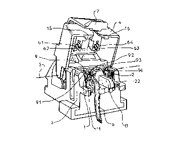
Figure l is a view in perspective of the rear part of a
telephone or computer socket, this rear part forming a device
for connecting, by insulation-displacing contacts, telephone or

CA 02203713 1997-04-2
computer lines with a wire ready to be connected and the con-
nection pusher in open position.
Figures 2 to 4 show, in partial longitudinal section along
IV-IV of Figure 5, the successive phases of connection of this
wire.
Figure 5 is a view in horizontal section along V-V of
Figure 4.
DESCRIPTION OF PREFERRED EMBODIMENT
Referring now to the drawings, Figure 1 shows the rear
part of a monopair modular jack socket. This socket comprises
two insulation-displacing metallic contacts 1, 2 which, in this
embodiment, each comprise two insulation-displacing slots, as
is the case for those described in US Patent 5,358,430
mentioned hereinabove.
As is more readily seen in Figure 2, these two insulation-
displacing metallic contacts l, 2 are each constituted by two
thicknesses of metal and are maintained in the rear plastic
body 3 of the socket. These insulation-displacing contacts may,
of course, each be constituted by a single thickness of metal.
Like the one of US Patent 5,358,430, this socket presents
a rotating connection pusher 4 made of plastics material which
is in the form of a pivoting cover, this pusher 4 rotating
about an axis 5 parallel to the row of insulation-displacing
contacts l, 2.
In Figure l, the two pairs of pusher-blades 61, 62 and 63,
64 are clearly distinguished, which, when the pivoting cover
will be closed, will drive ~he wires to be connected in their
receiving insulation-displacing slots of metallic contact 1 and
metallic contact 2, respectively.
By way of illustration, Figure l shows a wrapped telephone
wire 6 which is placed in position in the contact l, at the
inlet of its second insulation-displacing slot, and which is

CA 02203713 1997-04-2~
therefore ready to be connected by closure of the rotating
connection pusher 4.
According to the invention, the pivoting cover, or
rotating pusher 4 comprises an elastic end-of-stroke locking
catch 7, this catch 7 cooperating with a fixed end-of-stroke
locking stop 8. This stop 8 is formed by a prominent beak made
of plastics material, which forms part of the body 3 and is
obtained by moulding therewith.
As will now be shown with reference to Figures 2 to 5
which illustrate the functioning thereof in detail, the locking
stop 8 cooperates, upon closure of the pivoting cover 4, with
the elastic catch 7 to create a hard point of passage which
corresponds to a maximum tension of this catch and, immediately
after passage of this hard point, suddenly to release this
catch 7 against the nose of the stop 8, producing a clearly
audible click which then indicates to the installer that the
insulation-displacing connection of the wire 6 is effectively
and positively made with absolute certainty.
Figure 2 shows the pivoting cover 4 at the beginning of
the phase of closure. At this stage, the elastic catch 7 just
rests, without tension, on the base of the convex ramp 81 which
is formed at the front of the stop 8 to receive and push this
elastic catch 7 progressively rearwards. The elasticity of the
latter is due to the fact that it is borne by the free end of a
tongue 71 made of plastics material of which the other end is
fast with the pivoting cover 4. At this stage, the pusher-blade
62 (Figure 1) has not yet begun its action of driving the wire
6 in its receiving insulation-displacing slot of the metallic
contact 1.
According to Figure 3, by continuing the manual action of
closure of the pivoting cover 4, the catch 7 is pushed rear-
wardly by the stop 8, along the convex ramp 81 thereof. The
elastic tongue 71 is then curved, as shown, and is therefore

. CA 02203713 1997-04-2~
subjected to a high elastic return tension. At this stage, the
pusher-blade 62 begins to drive the wire 6 in its receiving
insulation-displacing slot of the contact 1 and therefore to
strip and connect the wire 6.
At the end of ramp 81, there is then passage of a hard
point 82, then, according to Figure 4, very brutal release of
the elastic tongue 71 and locking of the pivoting cover 4 by
clipping ~7-8).
During this last phase, the pusher-blade 62 causes total
and positive insulation-displacing connection of this wire.
The sudden release of the tongue 71 after the passage of
the hard point 82-7 causes this tongue to strike the front
face, i.e. the nose, of the stop 8, very violently. The violent
shock of these two hard bodies then causes a clearly audible
click which, in accordance with the result expected by the
present invention, indicates to the installer that the
insulation-displacing connection of the wire 6 is effected
positively, therefore with absolute certainty.
It should be noted, as clearly shown in Figure 5, that the
positive locking of the cover 4 makes it possible to hold the
wire 6 well in its position of connection, thanks in particular
to a short vertical groove 9 for reception and hold of the wire
6 which is provided, opposite each insulation-displacing slot,
in the body 3, as well as to a conjugate short groove 10 which
is provided, on the inner face of the pivoting cover 4, to
close this groove 9, performing the role of a lid therefor.
The intensity of the click thus produced upon closure of
the cover 4 is typically at least equal to 45 decibels A.
It goes without saying that the invention is not limited
to the embodiment which has just been described. For example,
it is also applicaole to sockets which, like the one according
to US Patent 5,358,430 mentioned hereinabove, present a
plurality of closure pushers instead of one. It is likewise

. CA 02203713 1997-04-2~
.
applicable to devices provided with a non-pivoting connection
pusher which is closed for example by translation and not by
rotation. It is generally applied to the connector technology
industry and therefore not solely to the domain of telephone or
computer-related connector technology which has been mentioned
here only by way of preferred but non-limiting example.

Representative Drawing
A single figure which represents the drawing illustrating the invention.
Administrative Status

2024-08-01:As part of the Next Generation Patents (NGP) transition, the Canadian Patents Database (CPD) now contains a more detailed Event History, which replicates the Event Log of our new back-office solution.

Please note that "Inactive:" events refers to events no longer in use in our new back-office solution.

For a clearer understanding of the status of the application/patent presented on this page, the site Disclaimer , as well as the definitions for Patent , Event History , Maintenance Fee  and Payment History  should be consulted.

Event History

Description Date
Inactive: IPC expired 2018-01-01
Application Not Reinstated by Deadline 2006-11-30
Inactive: Dead - Final fee not paid 2006-11-30
Deemed Abandoned - Failure to Respond to Maintenance Fee Notice 2006-04-25
Deemed Abandoned - Conditions for Grant Determined Not Compliant 2005-11-30
Notice of Allowance is Issued 2005-05-30
Letter Sent 2005-05-30
Notice of Allowance is Issued 2005-05-30
Inactive: IPC assigned 2005-05-18
Inactive: Approved for allowance (AFA) 2005-05-05
Amendment Received - Voluntary Amendment 2004-11-01
Inactive: S.30(2) Rules - Examiner requisition 2004-06-16
Letter Sent 2002-03-01
Request for Examination Requirements Determined Compliant 2002-02-01
All Requirements for Examination Determined Compliant 2002-02-01
Request for Examination Received 2002-02-01
Application Published (Open to Public Inspection) 1997-11-02
Letter Sent 1997-09-29
Inactive: IPC assigned 1997-07-31
Inactive: First IPC assigned 1997-07-31
Inactive: Single transfer 1997-07-28
Inactive: Filing certificate - No RFE (English) 1997-07-21
Inactive: Courtesy letter - Evidence 1997-05-27

Abandonment History

Abandonment Date Reason Reinstatement Date
2006-04-25
2005-11-30

Maintenance Fee

The last payment was received on 2005-03-31

Note : If the full payment has not been received on or before the date indicated, a further fee may be required which may be one of the following

  • the reinstatement fee;
  • the late payment fee; or
  • additional fee to reverse deemed expiry.

Patent fees are adjusted on the 1st of January every year. The amounts above are the current amounts if received by December 31 of the current year.
Please refer to the CIPO Patent Fees web page to see all current fee amounts.

Fee History

Fee Type Anniversary Year Due Date Paid Date
Application fee - standard 1997-04-25
Registration of a document 1997-07-28
MF (application, 2nd anniv.) - standard 02 1999-04-26 1999-03-17
MF (application, 3rd anniv.) - standard 03 2000-04-25 2000-03-14
MF (application, 4th anniv.) - standard 04 2001-04-25 2001-03-15
Request for examination - standard 2002-02-01
MF (application, 5th anniv.) - standard 05 2002-04-25 2002-03-18
MF (application, 6th anniv.) - standard 06 2003-04-25 2003-04-04
MF (application, 7th anniv.) - standard 07 2004-04-26 2004-04-05
MF (application, 8th anniv.) - standard 08 2005-04-25 2005-03-31
Owners on Record

Note: Records showing the ownership history in alphabetical order.

Current Owners on Record
POUYET S.A.
Past Owners on Record
XAVIER FASCE
Past Owners that do not appear in the "Owners on Record" listing will appear in other documentation within the application.
Documents

To view selected files, please enter reCAPTCHA code :


To view images, click a link in the Document Description column. To download the documents, select one or more checkboxes in the first column and then click the "Download Selected in PDF format (Zip Archive)" or the "Download Selected as Single PDF" button.

List of published and non-published patent-specific documents on the CPD .

If you have any difficulty accessing content, you can call the Client Service Centre at 1-866-997-1936 or send them an e-mail at CIPO Client Service Centre.


Document
Description 
Date
(yyyy-mm-dd) 
Number of pages   Size of Image (KB) 
Representative drawing 1997-12-08 1 13
Description 1997-04-24 6 239
Abstract 1997-04-24 1 14
Drawings 1997-04-24 3 79
Claims 1997-04-24 1 45
Description 2004-10-31 6 241
Claims 2004-10-31 1 44
Courtesy - Certificate of registration (related document(s)) 1997-09-28 1 118
Filing Certificate (English) 1997-07-20 1 165
Reminder of maintenance fee due 1998-12-29 1 110
Reminder - Request for Examination 2001-12-30 1 117
Acknowledgement of Request for Examination 2002-02-28 1 180
Commissioner's Notice - Application Found Allowable 2005-05-29 1 161
Courtesy - Abandonment Letter (NOA) 2006-02-07 1 166
Courtesy - Abandonment Letter (Maintenance Fee) 2006-06-19 1 175
Correspondence 1997-05-26 1 36